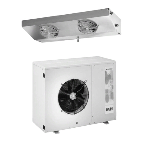
Rivacold CO2NNEXT User manual

rev01 - 08/2018
IT
EN
DE
FR
ES
ISTRUZIONI PER L’ASSEMBLAGGIO
ASSEMBLY INSTRUCTIONS
MONTAGEANLEITUNG
INSTRUCTIONS POUR L’ASSEMBLAGE
INSTRUCCIONES PARA EL ENSAMBLADO
CO2NNEXT

CO
2
NNEXT
rev.01
EN
60 / 293
Company Rivacold s.r.l. - All rights reserved
These assembly instructions are entrusted to users of CO2Nnext, for the instruction of the technicians involved in
installation and maintenance. The instructions, drawings, tables and anything else contained in this instruction
manual are of a reserved technical nature and cannot be reproduced and/or disclosed, either completely or
partially, without the specific written authorisation of Rivacold s.r.l.
The installation and maintenance technicians are explicitly prohibited from disseminating the information
contained and from using this manual for purposes other than for those strictly related to efficient preservation
of the machine.
The company Rivacold s.r.l. cannot be held responsible or liable for damages caused by incorrect use of the
documentation. In order to avoid incorrect manoeuvres that could cause danger to persons it is important to
read and understand all the documentation accompanying the machine.
Manufacturer's Name
Rivacold s.r.l.
Address
Via Sicilia, 7
Fraz. Montecchio 61022
VALLEFOGLIA (PU)
Telephone
(+39) 0721 919911
Telefax
(+39) 0721 490015

CO
2
NNEXT
rev.01
EN
61 / 293
Index
1.4.1. Definitions .........................................................................................................
1.4.2. Personal protection equipment and rules of conduct............................
1.4.3. Graphical conventions..................................................................................
1.6.1. General conditions.........................................................................................
1.6.2. Operations that invalidate the Warranty...................................................
1.7.1. Request for assistance...................................................................................
2.2.1. Passive safety devices ...................................................................................
2.2.2. Active safety devices.....................................................................................
2.2.3. Protection systems ..........................................................................................
2.2.4. Notifications .....................................................................................................
3.1.1. Name.................................................................................................................
3.1.2. Frame and components layout...................................................................
3.1.3. Technical data................................................................................................
3.1.4. Noise..................................................................................................................
4.3.1. Lifting .................................................................................................................
4.4.1. Power and control electrical panel and electrical connection...........
4.4.2. Refrigerating connection..............................................................................
4.4.3. System drain.....................................................................................................
4.4.4. Refrigerant load ..............................................................................................
4.4.1. Oil load..............................................................................................................
5.1.1. Interventions and relative periodicity .........................................................
5.3.1. Disassembly......................................................................................................
5.3.2. Dismantling and disposal...............................................................................

CO
2
NNEXT
rev.01
EN
62 / 293

CO
2
NNEXT
rev.01
EN
63 / 293
1. General information
1.1.General introduction
These assembly instructions are an integral part of the product CO2NNEXT (identified, in this document, with
the term partly-completed machine) produced by the company Rivacold s.r.l.; for this reason, they will need
to be part of the technical dossier of the final machine onto which this partly-completed machine will be
incorporated.
These instructions have been written to provide the technicians involved in the installation and maintenance
of the partly-completed machine with the essential information and instructions to operate correctly and
safely.
ATTENTION: Needing to be easily and immediately available, these instructions must be kept in a
place that is known and accessible to all.
NOTE: The purchaser may request a copy of this document (for example, in case of damage to the
original document) with a written request to the Manufacturer's Technical Office (see Section 1.7.1
"Request for Assistance"), engaging, in any case, to return the damaged copy.
1.2.Proprietary information
These assembly instructions contain confidential proprietary information. All rights
reserved.
These instructions may not be reproduced or photocopied, in whole or in part, without the prior written
consent of the Manufacturer. Only the purchaser may use this documentary material to whom the instructions
have been provided as a kit of the partly-completed machine and only for the purposes of installation and
maintenance of the partly-completed machine to which the instructions refer.
The Manufacturer declares that the information contained in these instructions is consistent with the technical
and safety specifications of the partly-completed machine to which the instructions refer. The drawings,
diagrams and technical data shown are updated at the date of publication of this document and are valid
only for the partly-completed machine to which they have been attached.
The Manufacturer reserves the right to apply changes or improvements to this documentation without prior
notification.
The Manufacturer assumes no responsibility for direct or indirect damage to persons, property or pets resulting
from use of this documentary material or of the partly-completed machine in conditions other than those
provided for.
1.3.Contents of the assembly instructions
These assembly instructions are intended for technicians in order to be able to understand and install the
partly-completed machine correctly.
In fact, these instructions provide, in addition to a description of the partly-completed machine, instructions
and indications for:
x
correct transportation and installation of the partly-completed machine;
x
performing of correct cleaning, adjustment and maintenance of the machine;
x
drawing attention to the most important safety and accident-prevention rules.
It is necessary to carefully read all the chapters in order to understand the indications provided in these
instructions and to operate with the partly-completed machine; for subsequent and easier searching through
the contents, refer to Table 1, containing a description of the topics addressed in the chapters.

CO
2
NNEXT
rev.01
EN
64 / 293
CHAPTER
CONTENT
Chapter 1 General
information
x
Description of the assembly instructions, of their structure and of the
conventions used;
x
definition of the terms used;
x
definition of the relationship between the Manufacturer and the
Purchaser/User (in terms of warranty and assistance conditions).
Chapter 2
Introduction on safety
x
Presentation of general indications on the partly-
completed machine, on
the solutions adopted for the protection of operating personnel;
x
Presentation of the residual risks present
Chapter 3
Description of the
partly-completed
machine
x
Description of the partly-completed machine
x
presentation of the main technical data concerning the partly-
completed
machine.
Chapter 4
Transport and Installation
x
Description of the methods for lifting and handling of the partly-
completed machine;
x
description of the installation methods, electrical connection and
commissioning of the partly-completed machine;
x
description of the mode of storage of the partly-completed machine.
x
Description of the partly-completed machine uninstallation.
Chapter 5
Maintenance and
demolition
x
Description of the verification and control procedures of the parts and
components of the partly-
completed machine (in particular, of the parts
most subject to wear);
x
description of the procedures that allow the designated personnel to
clean the partly-completed machine;
x
presentation of the instructions for disassembling, demolishing and
disposing of the partly-completed machine.
Chapter 6
Options
x
Description of the options available for installation on the partly-
completed machine.
Chapter 7
Troubleshooting
x
List of possible malfunctions of the partly-completed machine and the
related solutions.
Chapter 8
Annexes
x
Indications on the:
x
Technical datasheets of the possible versions of the partly-completed
machine;
x
refrigeration diagram;
x
documentation of components fitted to the partly-completed machine.
x
declaration of incorporation
Table 1 – Structure of the assembly instructions

CO
2
NNEXT
rev.01
EN
65 / 293
1.4. Conventions and definitions
The assembly instructions for the partly-completed machine were divided into chapters to enable, for each
life phase of the partly-completely machine (transportation, installation, maintenance and decommissioning)
readily available information necessary for the user of the partly-completed machine.
The entire documentation relating to the partly-completed machine was prepared by developing the topics
indicated by the Machinery Directive (2006/42/EC), by the PED Directive (2014/68 EU) and by the current
safety regulations.
The configuration of certain elements or devices described or represented in the documents may differ from
that composing the partly-completed machine in the specific set-up created according to particular
requirements or safety regulations; in this case, certain descriptions, references or best practices may have a
generic character while retaining their effectiveness.
Dimensional drawings and photographs are provided as an example as a reference for easier understanding
of the text.
1.4.1.
Definitions
PARTLY-COMPLETED MACHINE: it is the term used in these Assembly Instructions to indicate the CO2NNEXT.
P.P.E.: it is the acronym for Personal Protective Equipment.
DANGEROUS ZONE: Any area inside or near the machine in which the presence of an exposed person is a risk
to the health and safety of the person.
USER: Any person (entrepreneur/company) who adequately uses the partly-completed machine or who
entrusts its related use or operations to instructed persons.
EXPOSED PERSON: Any person wholly or partially present in a dangerous zone or near such areas.
MECHANICAL MAINTENANCE TECHNICIAN: Qualified technician allowed to work on any mechanical
component, to carry out the necessary adjustments, repairs and maintenance intervention.
The mechanical maintenance operator is not permitted to carry out interventions on powered electrical
plants.
ELECTRICAL MAINTENANCE TECHNICIAN: a qualified technician in charge of electrical works (adjustment,
maintenance, repairs) and, when necessary, works inside powered electric cabinets and the junction boxes.
HANDLING PERSONNEL: Qualified personnel who carry out the tasks of handling the partly-completed
machine or the materials used if the operation requires the use of lifting devices.
MANUFACTURER’S TECHNICIAN: Qualified technician provided by the manufacturer of the partly-completed
machine to carry out operations of a complex nature in particular situations or, in any case, when agreed
with the user.
1.4.2.
Personal protection equipment and rules of conduct
For each of the operations described in these instructions are indicated the means of protection that
personnel are required to use and the rules of conduct that allow protection of the safety of the operators
themselves.

CO
2
NNEXT
rev.01
EN
66 / 293
1.4.3.
Graphical conventions
The graphic layout of these Assembly Instructions is such as to allow easy recognition of the contents; in this
context, for example, the instructions are associated with lists, as indicated below:
•
This symbol identifies a generic bulleted list or list in points consisting of simple actions
(the order in which the actions are presented is not mandatory but recommended);
1.
In this way a numbered explanatory list of a complex procedure is identified (the
order in which the actions are
presented is mandatory to correctly and safely
perform the intervention in question).
italic text
Italicised text is used, in particular, for:
x
cross-
references; the cross references used in these instructions are expressed in
the following form:
"Paragraph/Table" with the number and, in general, the
specification "of the Chapter" with the number and the relative name (when it is
not specified it is implied that the paragraph or the table belong to the current
chapter);
x
the technical and specialised terms, the first time they appear in the text;
x
foreign terms which are not commonly used (normally, the first time they appear
in the text).
bold text
Bold text is used to highlight words, phrases or parts of the procedure.
Editorial pictograms
To ensure further knowledge of the partly-completed machine, the text of these assembly instructions is
accompanied by indications that complete them, providing additional information, highlighting tasks that
require essential attention and also particularly significant hazards to consider; in this regard, the following
notation is used:
DANGER: It indicates situations or operations that must be performed or information to which
particular attention must be paid to prevent causing injuries to persons.
WARNING: It indicates situations or operations in which there is the possibility of causing damage to
the machine or to the equipment connected to it.
ENVIRONMENTAL NOTE: It indicates situations or operations in which there is the
possibility of causing
damage to the environment.
NOTE: it indicates the notes, warnings, suggestions and other points to which to draw the reader's
attention or to complete the explanation with further information.
Personal Protective Equipment (PPE)
This paragraph indicates the graphic symbols used in these instructions to indicate the need to use certain
PPE.
SYMBOL
DESCRIPTION
Itindicates the need to use suitable head protectors to perform the described operation.
It indicates the necessity to use suitable protective gloves to perform the operation described
(possibly of the dielectrics type for operations on the electrical system).
It indicates the necessity to use suitable protective clothing to perform the operation described.
It indicates the necessity to use suitable safety shoes to perform the operation described.
It indicates the necessity to use protective goggles to perform the operation described.
Table 2 – Individual protection devices

CO
2
NNEXT
rev.01
EN
67 / 293
1.5. Testing
The partly-completed machine is directly tested by the manufacturer during the production phases at the
headquarters of Rivacold s.r.l.
1.6. Warranty
1.6.1.
General conditions
The Manufacturer, Rivacold s.r.l., guarantees the partly-completed machine and the equipment produced
by the Manufacturer itself as being free from material and processing defects for a period that is agreed
upon when the contract for the sale of the same machine is concluded.
The parts subject to wear and all the tools and consumables supplied by the Manufacturer together with the
machine are excluded from the warranty.
1.6.2.
Operations that invalidate the Warranty
Any attempt to disassemble, modify or tamper with a component of the partly-completed machine by the
user or by unauthorised personnel entails invalidating of the warranty and exempts the Manufacturer from
any responsibility for any damage to persons or property. deriving from such tampering.
The Manufacturer is also deemed to be exempted from any liability with invalidation of the warranty relating
to the partly-completed machine in the following cases:
x
unforeseen uses of the partly-completed machine (see Section 2.5 "Proper and improper use of the
partly-completed machine");
x
use contrary to that required by the regulations in force in the country of use;
x
installation of the partly-completed machine under conditions other than those specified in Chapter 4
- Transport and Installation;
x
installation not compliant with the specifications provided in Chapter 4 - Transport and Installation;
x
full or partial failure to comply with the instructions provided in this instruction manual;
x
non- or incorrect maintenance;
x
use of spare parts which are not original or not specified by the Manufacturer.
1.7. Assistance
Regarding the maximum exploitation of the services provided by the partly-completed machine and the
extraordinary maintenance operations, this instruction manual does not replace the experience of trained
and qualified installers, users and maintenance technicians.
In this case, the Technical Assistance Service of Rivacold s.r.l. provides:
x
telephone support regarding the simplest features and interventions that can be performed on the
PARTLY-COMPLETED MACHINE;
x
sending of documentary material;
WARNING: If in any doubt about the correct interpretation of the instructions provided in these
assembly instructions, contact the Technical Assistance Service (as indicated below) to obtain the
NECESSARY clarifications.
1.7.1.
Request for assistance
The Technical Assistance Service contact details are:
TECHNICAL OFFICE OF THE COMPANY RIVACOLD S.R.L.
Telephone: (+39) 0721 919911 - Telefax: (+39) 0721
490015
Via Sicilia, 7 - Fraz. Montecchio
61022 VALLEFOGLIA (PU) - ITALY
Provide the name, model and serial number of the partly-completed machine when asking for assistance.

CO
2
NNEXT
rev.01
EN
68 / 293
2. Introduction on safety
2.1. Design criteria
In designing the partly-completed machine principles and concepts have been applied according to the
paragraphs on the harmonised standards indicated in Table 3.
STANDA
NAME
EC Directive no. 2006/42
Machine Safety Directive
UNI EN ISO 12100: 2010
Machinery safety - Fundamental concepts, main
design principles - Part 1: Main concepts, general
principles for design
UNI EN ISO 12100: 2010
Machinery safety - Fundamental concepts,
maindesign principles - Part 2: Technical principles
UNI EN ISO 13857: 2008
Safety of machinery –
Safety distances to prevent hazard zones being reached by
upper and lower limbs
UNI EN ISO 14120: 2015
Machinery safety – Guards -
General requirements for the design and construction
of fixed and mobile guards
UNI EN 378-1: 2017 Refrigeration systems and heat pumps – Safety and environmental requirements –
Part 1: basic requirements, definitions, classification and selection criteria
UNI EN 378-2: 2017 Refrigeration systems and heat pumps – Safety and environmental requirements-
Part 2: design, construction, testing, marking and documentation
IEC EN 60204-1: 2006 Safety of machinery - Electrical equipment of machines - Part 1: General rules
Table 3 - Main harmonized standards used to design the partly-completed machine
Compliance with the relevant paragraphs of the afore-mentioned harmonised standards has made it
possible to eliminate or reduce risks in the best way possible, both during normal operation and during
maintenance operations.
The components used have been carefully chosen from those available on the market; the materials the
partly-completed machine is made of involve no risks to the health and integrity of persons. All parts supplied
by third parties are CE-marked (when envisaged) and comply with the relevant directives of reference. All
components have been strictly controlled in accordance with the quality standards prescribed by the current
regulations.
For the partly-completed machine, the necessary warning and protection measures have been adopted in
relation to the residual risks (see, in this regard, Section 2.3 "Residual Risks").

CO
2
NNEXT
rev.01
EN
69 / 293
2.2. Devices and Solutions for protection
2.2.1.
Passive safety devices
For the partly-completed machine the devices and constructive solutions described below were adopted:
x
fixed guards close to the moving parts;
x
external fairing with fixed access doors (if present);
x
safety signs corresponding to the guards of the partly-completed machine.
2.2.2.
Active safety devices
For the partly-completed machine, the active safety devices described below were adopted:
x
Maximum safety pressure switch for each automatic reset compressor (PSH) or for specific versions
with safety pressure switch for each manual reset compressor (PZH);
x
Safety valve on the MT and LT circuit low pressure side (if present);
x
Safety valve(s) on the intermediate receiver;
x
Safety valve on the high pressure side, (if present).
The valve calibration is shown on the valves themselves and has been dimensioned on the basis of the
indications of the EN 13136 standard.
ATTENTION: It is absolutely forbidden to modify the calibration of the safety pressure switch and/or to inhibit
its operation.
2.2.3.
Protection systems
The system is equipped with protections to safeguard anomalous situations acting on both the pressure and
voltage circuits.
Excessive pressure inside the refrigeration circuit
The safeguard against excess pressure inside the refrigerating circuit during discharge, which beside
compromising system operation, can also be dangerous to the personnel, has two intervention steps:
x
When the pressure reaches values exceeding the acceptable conditions, values determined
according to the characteristics of the refrigerant adopted, from the sizing of the system and from the
characteristics of the compressor, the maximum pressure switches intervene which cause the
associated compressor to stop. Resetting the system operation can occur automatically or through
manual intervention, which should only be carried out after having removed the fault cause. The
resetting differs on the basis of the machine characteristics.
ATTENTION: It is strictly forbidden to change calibration of the high pressure safety switches once
testing has been carried out during initial start-up.
x
Regarding all the safety valves on the low pressure and high pressure side; the calibration is shown on
the valve itself and has been calculated on the basis of the indications of the EN 13136 standard. The
intervention of these devices causes leakage and loss, in whole or in part, of the refrigerant loading
into the system.

CO
2
NNEXT
rev.01
EN
70 / 293
Refrigerant pressure defect
The causes that can cause lowering of the intake pressure beyond the values permitted in the project are:
x
defect in the quality of refrigerant loaded;
x
poor regulation of the thermostatic valves;
x
gas leaks that reduce the load.
This entails a drastic reduction in the thermodynamic efficiency of the system and can cause compressor
failure. If the reduction occurs at values lower than the calibration one, the protection from electronic control
of minimum pressure comes into operation. This intervention blocks the compressor motor and reset is
automatic. If the intake side pressure increases again, the system automatically restarts. This can of course be
accepted if it were a transitory phenomenon while it requires maintenance if the phenomenon continues to
be repeated.
Electronic control malfunction
In the event of malfunction of the electronic control acting on the compressors, electronic valves and on the
gas-cooler, there may be limited functionality or system shutdown depending on the type of fault. The high
pressure safety related to the pressure switches, independent of the electronic control, continues to be
active. Probe reading failure or breakage of the probes, related to electronic control, may limit certain
features or generate system shutdown. All malfunctions can be acquired by a supervisory system. Malfunction
of the electronic control does not generate a risk for personal safety.
Insufficient lubrication of the compressor
In the oil circuit (if any) there is an oil separator, positioned on the general supply route, which redistributes the
oil collected to the compressors themselves through appropriate logics and circuits.
Furthermore, the electronic control includes checking of the compressor speed in order to guarantee the
correct oil return to the compressor.

CO
2
NNEXT
rev.01
EN
71 / 293
2.2.4.
Notifications
The partly-completed machine is equipped, in addition to the luminous signals and the instruments installed
on the panel of the electrical panel, with indicator lights on the inside.
To access it, it may be necessary to remove one or more covering panels that close the structure.
For further information on the light signals and on the instruments of the electrical panel, refer to the wiring
diagram and to the relative documentation attached to this manual.
ATTENTION: Operations with the panel removed should only be performed by authorised/qualified
personnel.
Observe all foreseeable safety precautions and use the necessary PPE. At the
end of the intervention, always carefully replace all the panels removed.
Liquid passage light
It is a transparent indicator that is installed along the liquid line which allows understanding of the load state.
When the system is at full speed, the flow through the sight glass must be continuous and free from foams or
gas bubbles. If there is considerable turbulence with the presence of gas, wait a few minutes before
correcting the load; it could be a transitory phenomenon caused by rapid opening of a thermostatic valve.
Humidity reporting
On the liquid passage indicator it is possible to observe a coloured element that indicates if the refrigerant is
dry or contains moisture. Based on the colour, it is possible to understand the status.
In the presence of moisture it is possible to replace the dehydrating filter. Should the problem persist it is
necessary to stop the system, empty it and repeat the empty and load phases.
Oil level indicator light
It is installed on the oil separator (if present) and indicates the minimum level. Depending on the version of the
partly-completed machine there may be a second indicator to identify the maximum level. The oil level
check must be carried out when the system is fully operational for a few hours and for a few days after
starting.
If it is necessary to top up, always use only the type of oil indicated on the plate of the machine and/or in the
enclosed documentation.
Pressure reporting
The pressure reading at the different points of the circuit is possible by:
x
electronic control;
x
The installation of pressure gauges.
The pressure gauges must be connected to the service valves on the various points of the circuit. In case of
faired units, to access the connection points, it is necessary to remove the covering panels.
Indication of presence of malfunctions and presence of alarms
The presence of alarms is signalled by a red light directly on the electronic control terminal located on the
door of the partly-completed machine. The light can be flashing or fixed; in the first case, the light indicates
the presence of active and unseen alarms, the second identifies that the alarm has been viewed.
A red light on the electronic control display in the panel area generally indicates the malfunction and/or
alarms presence status. The specific cause can be identified by interrogation of the electronic control. These
signals can be acquired by a supervisory system.
Some alarms can be of manual reset type and therefore the intervention of a technician on the partly-
completed machine is required.
DANGER: Manual reset of the system or part of it following an anomaly involves the intervention of a
specialist technician who only after having analysed the causes and having resolved the problem
can restart the system.
DANGER: With R744 (CO2) refrigerant all operations must be carried out only by specialist
technicians trained to operate with this type of refrigerant.

CO
2
NNEXT
rev.01
EN
72 / 293
2.3. Residual risks
To avoid any dangerous condition for persons or damage to the partly-completed machine caused by
residual risks, i.e. those risks that persist despite all provisions implemented, or potential risks which were not
obvious, the manufacturer recommends that maintenance personnel and all personnel in charge of
operating the partly-completed machine strictly follow the warnings indicated in the following pages.
ATTENTION: Always comply with the signs and indications of the plates applied to the machine and
operate exclusively according to the instructions provided in this instruction manual.
ATTENTION: All operations to be performed on the machine must be performed by qualified, trained,
informed or properly equipped personnel.
Residual risk of intoxication
To avoid impacts or damage that could cause leaks of gases dangerous to human health, install the machine
in a dry, protected and sufficiently ventilated place in compliance with the laws of the country of installation.
Residual risk of burns
Before carrying out any work on the machine, make sure that the hot surfaces have cooled down; wear
protective gloves to avoid burns.

CO
2
NNEXT
rev.01
EN
73 / 293
2.4. Safety Plates
The warning plates shown in Table 4 are present on the partly-completed machine.
PLATE
DESCRIPTION
It indicates the prohibition to remove the devices and the safety
protections installed; it
is typically also accompanied by an explanatory text: DO NOT
REMOVE THE PROTECTIVE DEVICES.
It indicates the prohibition to perform any intervention (including lubrication and
cleaning)
close to moving parts; typically, it is also accompanied by an explanatory
text:
DO NOT REPAIR OR ADJUST WITH PARTS IN MOTION.
It signals the danger, due to the presence of mobile parts close to the zone ofthe partly
-
completed machine where it is located.
It reports the danger of electrical voltage.
It reports the danger of hot surfaces.
It reports the obligation to read the assembly manual/instructions.
Indicates it is forbidden to touch the zone where it is positioned
Pressurised nitrogen.
Remove the voltage from the disconnector before carrying out maintenanceon the
machine. Remove power to the entire system before carrying out operations inside the
panel.
Itis forbidden to connect other devices to the control transformer.
Obligation to convey the discharge of the safety valves.
Table 4 - Description of the warning labels on the machine.

CO
2
NNEXT
rev.01
EN
74 / 293
Position of the pictograms on the partly-completed machine
1.
On all the air exchangers present in the machine
2.
On each surface subject to high temperatures
3.
On each energised part

CO
2
NNEXT
rev.01
EN
75 / 293
2.5. Proper and improper use of the partly-completed machine
The partly-completed machine which is the subject of these assembly instructions has been designed and
constructed exclusively for refrigeration. The partly-completed machine is configured to use only R744 (CO2)
refrigerant gas.
The manner in which each partly-completed machine is designed to use only the above refrigerant is
specified. It is therefore important to use the partly-completed machine in compliance with the refrigerant
fluid for which it was designed and built and as received from the Manufacturer.
The partly-completed machine has been designed and built to work in environments where there is no
potentially explosive atmosphere.
The partly-completed machine must be adequately protected from atmospheric agents.
It is a good precautionary measure to have powder extinguishers in the vicinity of the partly-completed
machine. To prevent the possibility of fire, keep the partly-completed machine clean of plastic pieces, oil,
solvents, paper and rags.
Use of the partly-completed machine for different operations could cause harm to persons or damage to the
machine itself and are therefore considered improper use for which the manufacturer is not responsible.
DANGER: The user MUST view the type of gas contained in the partly-completed machine and its
quantity in order to operate properly.
ATTENTION: In case of different use, it is essential to consult in advance with the Manufacturer's
Technical Office.
DANGER: With R744 (CO2) refrigerant all operations must be carried out only by specialist technicians
trained to operate with this type of refrigerant.
2.6. Incorporation statement
This document is accompanied by a Declaration of Incorporation which will be issued by the manufacturer at
the time of purchase.

CO
2
NNEXT
rev.01
EN
76 / 293
2.7. General Warnings and Rules of Conduct
In order to avoid any risk to persons or damage to the machine, it is advisable to strictly follow the warnings
and general rules of conduct reported here.
DANGER WARNING: the Manufacturer disclaims any liability for any damage to property and/or
persons arising from improper operations carried out by unqualified, untrained or unauthorized
personnel.
x
Operators in charge of operation of the partly-completed machine must be adequately trained to
best use it, with no risk, and must work in a comfortable environment that guarantees the best possible
safety and hygiene conditions.
x
Prior to using the partly-completed machine ensure that any hazardous conditions for safety have
been removed and no operators are present in the danger area near the partly-completed machine.
x
After removing the packaging, make sure all machine parts are intact, otherwise contact your dealer.
x
Before using the partly-completed machine, make sure all guards or other protections are fitted and
that all safety devices are present and working.
x
Carefully read the labels on the partly-completed machine, do not cover them and replace them
immediately if damaged.
x
Do not place containers of liquids on the partly-completed machine.
x
Consult these instructions on the safety provisions in force and the specific PPE to implement for staff
safety; in particular, the staff responsible for the partly-completed machine must wear suitable
clothing, avoiding or paying due attention to:
o
loose clothing,
o
wide sleeves,
o
ties or draping scarves,
o
necklaces, bracelets and rings.
x
Staff responsible for maintenance of the partly-completed machine must be aware of all the
procedures outlined in Chapter 5 - Maintenance and Demolition and have adequate technical
preparation to correctly interpret the instructions and diagrams attached to these instructions and to
intervene on the partly-completed machine.

CO
2
NNEXT
rev.01
EN
77 / 293
x
The area where the maintenance operations are carried out must always be clean, dry and with the
appropriate equipment always available and efficient.
x
If it is necessary to perform interventions in the vicinity of electrical components, operate with dry
hands and use dielectric gloves.
x
If the machine is installed in a position not easily accessible to the operator, it is necessary to have
suitable structures to allow access to the intervention areas.
DANGER: It is necessary to ensure that before starting any type of intervention on the machine or on
it
s components or accessory equipment, the power supply is disconnected; if this is not possible, it is
necessary to provide precautions that in any case allow operating in safety close to the partly
-
completed machine.
DANGER: The leaking of refrigerant gas following intervention of the safety valve can cause
damage to property and/or to persons.
DANGER: Tampering with or unauthorised replacement of one or several parts of the partly
-
completed machine and the use of accessories, tools and consumables other
than those indicated
by the Manufacturer may result in an accident.
DANGER: The R744 (CO2) refrigerant is colourless and odourless. Its presence in the environment
can cause asphyxiation. All operations must be performed in the presence of gas presence
detectors and in compliance with the safety regulations of the country of installation.
ATTENTION: With R744 (CO2) refrigerant all operations must be carried out only by specialist
technicians trained to operate with this type of refrigerant.
ATTENTION: With R744 (CO2) refrigerant all operations must be carried out in the presence of gas
presence detectors.
ATTENTION: All materials with an environmental impact that must be eliminated as a result of
interventions or work on the machine must be disposed of
according to the regulations in force. If
necessary, use specialist facilities for their disposal.

CO
2
NNEXT
rev.01
EN
78 / 293
3. Description of the partly-completed machine
The partly-completed machine models that are the subject of this document are faired condensing units for
use in commercial refrigeration. The faired condensing units are systems for positive and negative refrigeration
where the heat can be disposed of into the environment.
The faired condensing units are compact, low noise systems, suitable for working outdoors.
The partly-completed machine is designed and optimised to work with CO2 (R744).
The operating modes can be transcritical or subcritical depending on the conditions of the external
environment.
The electronic control, with appropriate logics, allows the partly-completed machine to always operate in
conditions of maximum efficiency in different environmental conditions and cold demand. It also manages
lubrication and any alarms signalling them on theelectronic control terminal and on any type of supervision.
Depending on the models, for the condensing unit, units can be provided with a single fan-motor, or with a
double fan.
The various models are equipped with the following refrigerator accessories:
x
BLDC compressor(s) driven by inverter;
x
control valves;
x
intermediate receiver;
x
dehydrating filter and liquid indicator;
x
on-board gas-cooler;
x
electrical panel with relative electronic control;
For the negative refrigeration models there is also a desuperheater (intercooler) incorporated in the gas-
cooler battery.
All models also have a casing heating element that prevents the accumulation of liquid in the lower area of
the compressor during downturn periods. The unit is always enclosed in a self-supporting housing made of
steel varnished with epoxy powder, and is equipped with electrical equipment with a main disconnecting
switch (the power supply wire that must be connected to the switch is not supplied).
The following variants are possible:
x
Only for TN/MT positive refrigeration;
x
Only for BT/LT negative refrigeration;
The compressors are managed by a dedicated inverter, which allows modulation of the capacity from 25 to
100%.
The compressor(s) of the partly-completed machine can be provided with a by-pass solenoid to facilitate
starting of the same. On the line, pressing each compressor, there is a non-return valve.
The machine is equipped with pressure switches and safety valves to address any malfunctions.
In addition there are: back-pressure valve (HPV) in general delivery after the gascooler, intermediate liquid
and gas separation receiver, a gas flash valve (VFL) to keep the pressure constant at the receiver itself (only
in certain configurations), a braze-weld liquid filter with relative indicator, liquid-intake heat exchanger (if
any), insulation of all cold parts, shut-off valves and service valves for easy maintenance.
An electric power panel with magneto-thermal switches and electronic control allows the power supply and
management of the entire gascooler system and intercooler (if any) included.
Table of contents
Other Rivacold Heat Pump manuals
Popular Heat Pump manuals by other brands

Daikin
Daikin Altherma 3 GEO EGSAH06UD Series installation manual

Hoval
Hoval BelariaSRM 4 User reference guide

Toshiba
Toshiba Super MMY-MAP0501HT7 installation manual

Worcester
Worcester waaiu5 installation manual

ANTEK
ANTEK AIR MAGNA 100 Installation and maintenance manual

Airwell
Airwell WELLEA MONO SPLIT A R32 installation manual

RV Products
RV Products 6535 SERIES Service manual

AWG
AWG SWIMSMART HEAT PUMPS SS110 owner's manual

Glen Dimplex
Glen Dimplex LA 60TU-2 Installation and operating instruction

SUMMER WAVES
SUMMER WAVES 6.5 Si Installation and user manual

Hoshizaki
Hoshizaki URC-6FE parts list

Daikin
Daikin Altherma EHBH04CBV User reference guide