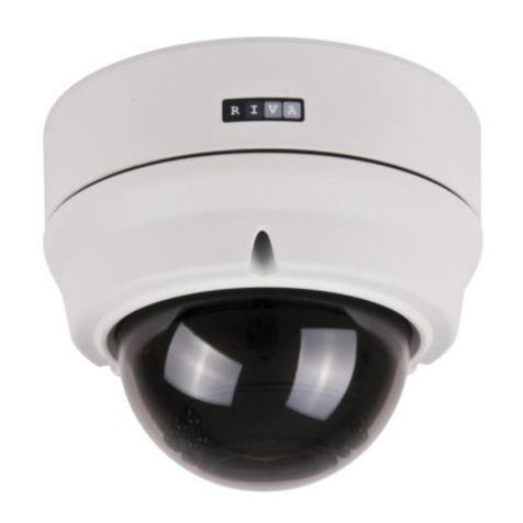
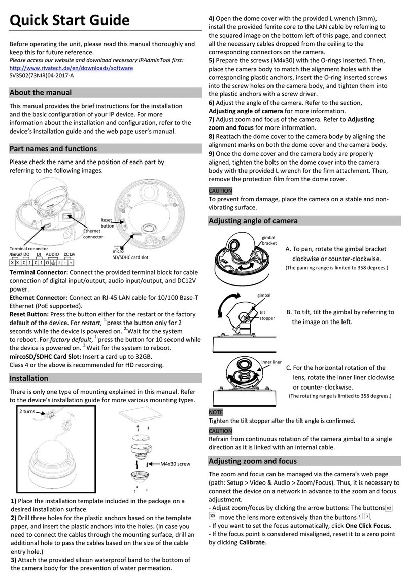
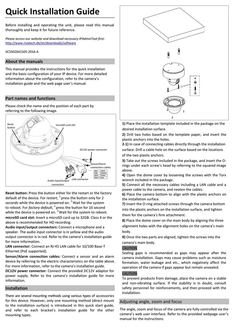
RIVATECH RC3510 User manual

1
www.rivatech.de
RC3510
RC3510RC3510
RC3510
Installation Guide
Installation GuideInstallation Guide
Installation Guide

2
www.rivatech.de
INFORMATION TO USER
INFORMATION TO USERINFORMATION TO USER
INFORMATION TO USER
CAUTION
RISK OF ELECTRIC S OCK,
DO NOT OPEN
CAUTION: TO REDUCE T E RISK OF ELECTRIC S OCK,
DO NOT REMOVE COVER (OR BACK).
NO USER SERVICEABLE PARTS INSIDE.
REFER SERVICING TO QUALIFIED SEERIVCE PERSONEL.
This symbol is intended to alert the user to the presence of un-
insulated “dangerous voltage” within the product’s enclosure that
may be of sufficient magnitude to constitute a risk of electric
shock to persons.
This symbol is intended to alert the user to the presence of
important operating and maintenance (servicing) instructions in
the literature accompanying the appliance.
!
!

3
www.rivatech.de
Table of Contents
Table of ContentsTable of Contents
Table of Contents
1.
1.1.
1.
FEATURES
FEATURESFEATURES
FEATURES ................................................................................ 5
2.
2.2.
2.
PACKAGE CONTENTS
PACKAGE CONTENTSPACKAGE CONTENTS
PACKAGE CONTENTS ................................................................. 6
3.
3.3.
3.
PART
PARTPART
PART
NAMES
NAMESNAMES
NAMES ........................................................................... 7
3.1.Internal View ................................................................................. 7
4.
4.4.
4.
INSTALLA
INSTALLAINSTALLA
INSTALLATION
TIONTION
TION ........................................................................ 10
4.1. Installation Template .................................................................... 11
4.2. Setting the Lens Position .............................................................. 11
4.3. Setting the Image Attribute ........................................................... 12
4.4. Operating the OSD Menu .............................................................. 12
5.
5.5.
5.
CONNECTIONS
CONNECTIONSCONNECTIONS
CONNECTIONS ........................................................................ 13
5.1. Connectors ................................................................................ 13
6.
6.6.
6.
CONFIGURATION
CONFIGURATIONCONFIGURATION
CONFIGURATION...................................................................... 16
6.1.Set up network environment .......................................................... 16
6.2. View video on web page ............................................................... 16
6.2.1. View video using IPAdmin Tool ................................................. 17
6.2.2.View video using IP address ..................................................... 18
6.3. Reset ........................................................................................ 18
6.4. Factory Default ........................................................................... 18
APPENDIX (A): SPECIFICATIONS
APPENDIX (A): SPECIFICATIONSAPPENDIX (A): SPECIFICATIONS
APPENDIX (A): SPECIFICATIONS ..................................................... 19
Summary .......................................................................................... 19
Environment Condition ........................................................................ 20
APPENDIX (B):
APPENDIX (B): APPENDIX (B):
APPENDIX (B): POWER OVER ET ERNET
POWER OVER ET ERNETPOWER OVER ET ERNET
POWER OVER ET ERNET ......................................... 22
PoE compatibility ................................................................................ 22
Power classification ............................................................................ 22
APPENDIX (
APPENDIX (APPENDIX (
APPENDIX (C
CC
C): DIMENSIONS
): DIMENSIONS): DIMENSIONS
): DIMENSIONS .......................................................... 23

4
www.rivatech.de
APPENDIX (
APPENDIX (APPENDIX (
APPENDIX (C
CC
C):
): ):
): EXADECIMAL
EXADECIMALEXADECIMAL
EXADECIMAL-
--
-D
DD
DECIMAL
ECIMALECIMAL
ECIMAL
C
CC
CONVERSION
ONVERSIONONVERSION
ONVERSION
T
TT
TABLE
ABLEABLE
ABLE ............. 24
REVISION ISTORY
REVISION ISTORYREVISION ISTORY
REVISION ISTORY ....................................................................... 25

5
www.rivatech.de
1
11
1.
..
.FEATURES
FEATURESFEATURES
FEATURES
Camera
CameraCamera
Camera
•Indoor/Outdoor Dome IP Camera (Vandal Proof)
•igh Quality Compression in real time streaming
•Sony 1/3” Super AD CCD & igh Quality SS- Q1 Full Kit Chip Set
Sony 1/3" Vertical Double Density Color CCD (Optional)
•True Day / Night (ICR) and WDR (Optional)
•Improvement of color rolling suppression
Streaming
StreamingStreaming
Streaming
•Dual streaming mode (such as different codec/resolution/bit rate and so on.)
•De-interlacing on DSP
•Burnt-in text supported
•Unicast/Multicast supported
Video/Audio
Video/AudioVideo/Audio
Video/Audio
•Video compression: .264/MPEG/MJPEG, 25/30FPS@D1(PAL/NTSC)
•Audio compression: G.711(µLaw, aLaw)/PCM
•Analog video out for external monitors
•Video Motion Detection supported
•Two-way mono audio supported
Network
NetworkNetwork
Network
•RTSP/ TTP protocol supported
•10/100 Base-T Ethernet
Additional Features
Additional FeaturesAdditional Features
Additional Features
•Micro SD card supported
•PoE supported
•Built-in Video Content Analysis
•OSD supported
•SDK (Software Development Kit) provided
VCA (Video
VCA (VideoVCA (Video
VCA (Video
Content Analysis)
Content Analysis)Content Analysis)
Content Analysis)
•VCA Presence (Included as basic)
•VCA Surveillance (Optional)

6
www.rivatech.de
2
22
2.
..
.
PACKAGE CONTENTS
PACKAGE CONTENTSPACKAGE CONTENTS
PACKAGE CONTENTS
Unpack carefully and handle the equipment with care. The packaging contains:
Camera
CameraCamera
Camera
DC power adaptor
DC power adaptorDC power adaptor
DC power adaptor
DC Jack Cable
DC Jack CableDC Jack Cable
DC Jack Cable
7
77
7-
--
-p
pp
pin
in in
in and 2
and 2and 2
and 2-
--
-pin
pin pin
pin terminal block
terminal blockterminal block
terminal block
Video out cable
Video out cableVideo out cable
Video out cable
Screws
ScrewsScrews
Screws
Camera hole cover and opener
Camera hole cover and openerCamera hole cover and opener
Camera hole cover and opener
ex wrench driver
ex wrench driverex wrench driver
ex wrench driver
Installation
Installation Installation
Installation t
tt
template
emplateemplate
emplate
Silicon waterproof band
Silicon waterproof bandSilicon waterproof band
Silicon waterproof band
Quick installation guide
Quick installation guideQuick installation guide
Quick installation guide
The above contents are subject to change without prior notice.
Note
i

7
www.rivatech.de
3
33
3.
..
.PART
PARTPART
PART
NAMES
NAMESNAMES
NAMES
3
33
3.
..
.1
11
1.Internal View
.Internal View.Internal View
.Internal View
1
11
1Focus puller
Focus pullerFocus puller
Focus puller
The focus puller is for adjusting the focus of the image focus. Move this puller left
or right and set to the desired focus. Refer to
4.2. Setting the Lens Position
for
more details.
2
22
2Zoom puller
Zoom pullerZoom puller
Zoom puller
The zoom puller is for setting the zoom position. Move this puller left or right and
set to the desired zoom position. Refer to
4.2. Setting the Lens Position
for more
details.
3
33
3Audio and IO terminal connector
Audio and IO terminal connectorAudio and IO terminal connector
Audio and IO terminal connector
A 7-pin terminal block is included in the device package. Connect this terminal block
into this connector for cable connection of audio input/output and digital
input/output. Refer to
5.1. Connector
for more details.
①
②
③
④
⑤
* Models herein and their
appearance are subject to
change
without any prior notice.

8
www.rivatech.de
4
44
4LAN connector
LAN connectorLAN connector
LAN connector
This is a RJ45 LAN connector for 10/100 Base-T Ethernet.
5
55
5Power Adap
Power AdapPower Adap
Power Adaptor Connector (DC 12V)
tor Connector (DC 12V)tor Connector (DC 12V)
tor Connector (DC 12V)
The camera needs a DC 12V 1A adapter for power supply.
6
66
6Fan
FanFan
Fan
The fan is implemented for controlling temperature and moisture of the internal
device. For its activation temperature, refer to the table below.
7
77
7eater
eatereater
eater
The heater is implemented for controlling temperature and moisture of the internal
device. The heater can be activated only when using DC 12V for the power source.
For its activation temperature, refer to the table below.
Bimetal
Bimetal Bimetal
Bimetal
for
forfor
for
Fan
FanFan
Fan
eater
eatereater
eater
On
45°C (±5°C)
5°C (±5°C)
Off
35°C (±5°C)
15°C (±5°C)
⑥
⑦
⑧
⑨
* Models herein and their
appearance are subject to change
without any prior notice.
⑩
⑪

9
www.rivatech.de
8
88
8Reset
Reset Reset
Reset button
buttonbutton
button
The reset button can be used for restarting the device or resetting it to Factory
Default. Refer to
6.3. Reset
and
6.4. Factory Default
for more details.
9
99
9Micro SD card slot
Micro SD card slotMicro SD card slot
Micro SD card slot
It is a memory card slot for external storage.
10
1010
10 Status LEDs
Status LEDsStatus LEDs
Status LEDs
The LEDs indicate system status. It works the same way as of the LEDs on the LAN
connector.
For the factory default setting, LED 2 blinks for the heartbeat and LED 1 turns on for
video signal. To change its setting, refer to the section
4.5.11. LED Setting
4.5.11. LED Setting4.5.11. LED Setting
4.5.11. LED Setting
of the
NVC Web Page User’s Manual.
NVC Web Page User’s Manual.NVC Web Page User’s Manual.
NVC Web Page User’s Manual.
11
1111
11 Video Out connector
Video Out connectorVideo Out connector
Video Out connector
Connect the 2-pin to BNC cable to the video out connector to use a displayer such as
a VCR or monitor.
LED
1
LED
2

10
www.rivatech.de
4
44
4.
..
.INSTALLATION
INSTALLATIONINSTALLATION
INSTALLATION
When assembling the main body of the camera and its
dome
cover, make sure they fit each other into place.
Note
i
1)
1)1)
1)
Place the installation template
that is provided in the package on
the desired position of installation.
2)
2)2)
2)
Attach the waterproof silicon
band on the bottom plate of the
device.
3)
3)3)
3)
Drill three holes on the
template and insert anchor blocks
into the holes. Fasten the camera
with screws.
4)
4)4)
4)
Make sure the cables are
properly connected by checking
the LED button. For the detailed
information, please refer to
3.1.
Internal View
.
5
55
5)
))
)
Adjust the lens position by
referring to
4.2. Setting the Lens
Position
.
6)
6)6)
6)
Put the dome cover on the
main body of the camera. Make
sure the main body and the cover
fit each other into place.

11
www.rivatech.de
The
camera
may fall off the ceiling even after the proper installation
and mounting. To prevent any accident,
make sure the ceiling is
firm and stable enough to support the camera
. If any reinforcement
is needed, consult with your safety personnel and proceed with t
he
installation.
4
44
4.
..
.1
11
1.
. .
.
Installation Template
Installation TemplateInstallation Template
Installation Template
4
44
4.
..
.2
22
2.
. .
.
Setting the Lens Position
Setting the Lens PositionSetting the Lens Position
Setting the Lens Position
Set the lens position and adjust the zoom and focus by performing procedures as
below.
Caution
!

12
www.rivatech.de
1) Remove the dome cover.
2) Adjust the lens to the desired position by manually moving its body in the following
directions.
3) Login to the web page of the device to view its real-time image. Refer to
Chapter 6.
Configuration
for details about using its web page.
5) Unscrew the focus puller by turning it counterclockwise. Move it left or right and
adjust the image focus. After the setting, tighten the focus puller again by turning it
clockwise.
4
44
4.
..
.3
33
3. Setting the Image Attribute
. Setting the Image Attribute. Setting the Image Attribute
. Setting the Image Attribute
You can set the image attribute of camera through the webpage.
The menu of image attribute can be seen under Setup > Video & Audio > Video
Setup > Video & Audio > VideoSetup > Video & Audio > Video
Setup > Video & Audio > Video-
--
-in >
in > in >
in >
Attribute Setting
Attribute SettingAttribute Setting
Attribute Setting. Brightness, contrast, hue, saturation and sharpness can be
adjusted.
4
44
4.
..
.4
44
4. Operating the OSD Menu
. Operating the OSD Menu. Operating the OSD Menu
. Operating the OSD Menu
To operate the OSD of camera, refer to the OSD Menu Control Manual
OSD Menu Control ManualOSD Menu Control Manual
OSD Menu Control Manual in the SDK.
C. Up or down movement
of lens body
4) Unscrew the zoom puller by
turning it counterclockwise.
Move it left or right and set the
lens to the desired zoom
position. After the setting,
tighten the zoom puller again by
turning it clockwise.
Focus puller
Zoom puller
A. Clockwise movement of
lens bottom holder
B. Left or right movement of
lens body

13
www.rivatech.de
5
55
5.
..
.CONNECTIONS
CONNECTIONSCONNECTIONS
CONNECTIONS
5
55
5.
..
.1
11
1. Connectors
. Connectors. Connectors
. Connectors
1
11
1Audio In / Out
Audio In / OutAudio In / Out
Audio In / Out
The camera has a mono audio input and a mono audio output. Since the output power
for the audio is low, an amplifier speaker is needed for a clearer sound (Do not use a
headphone or earphone directly to the camera).
AIn
AOut
Mic
Amp Speaker
Audio
DI
DO
12V DC
①
②
③
④

14
www.rivatech.de
2
22
2Sensor
SensorSensor
Sensor
(DI) connection
(DI) connection(DI) connection
(DI) connection
The camera provides 1 channel D/I. It can be connected to either a voltage type
sensor or a relay type sensor as the following figures. It can be selected by software.
Input voltage range: 0 VDC minimum to 24 VDC maximum
Input voltage threshold: 1 V
Do not exceed the maximum input voltage or relay rate.
3
33
3Alarm
AlarmAlarm
Alarm
(DO) connection
(DO) connection(DO) connection
(DO) connection
Only the relay type is supported.
Relay Rating: Max 24VAC 500mA or 12VDC 1A
Do not exceed the maximum relay rating.
Caution
!
Caution
!
+5V
DI
COM
DI
COM
+
-
Relay
Type
Voltage Type
+
-
Output of
Sensor
Output of
Sensor
Internal
Internal
+
-

15
www.rivatech.de
4
44
412V DC Power
12V DC Power12V DC Power
12V DC Power
A 12 DC power connector is required for this device.
12V
Red
Black
DO
COM
Relay Type
Device
Internal

16
www.rivatech.de
6
66
6.
..
.CONFIGURATION
CONFIGURATIONCONFIGURATION
CONFIGURATION
6
66
6.
..
.1
11
1.Set up network environment
.Set up network environment.Set up network environment
.Set up network environment
The default IP address of your IP device is 192.168.XXX.XXX. You can find the
available IP address from the MAC address of your device. Please make sure the device
and your PC are on the same network segment before running the installation. If the
network segment between your PC and the device is different, change your PC’s
settings as below.
IP address : 192.
192.192.
192.168.xxx.xxx
168.xxx.xxx168.xxx.xxx
168.xxx.xxx
Subnet mask: 255.255.0.0
255.255.0.0255.255.0.0
255.255.0.0
6
66
6.
..
.2
22
2. View video on web page
. View video on web page . View video on web page
. View video on web page
View the live video on a web page using your IP device and its IP address. You can use
the IPAdminTool or enter the IP address on the web page.

17
www.rivatech.de
6
66
6.
..
.2
22
2.
..
.1
11
1.
..
.
View video u
View video uView video u
View video using IPAdmin Too
sing IPAdmin Toosing IPAdmin Too
sing IPAdmin Tool
ll
l
IPAdminTool automatically searches all activated network encoders and IP cameras
and shows the product name, IP address, MAC address and etc. IPAdminTool is
provided with SDK at the following SDK path.
{SDK root}\BIN\TOOLS\AdminTool\
To use the IPAdminTool and view the live video on a web page:
1. Start IPAdminTool. Names and info of currently activated devices appear as a
list.
2. Right-click on the desired device and select Web view
Web viewWeb view
Web view.
3. Click pop
poppop
pop-
--
-up blocked
up blockedup blocked
up blocked and install the ActiveX setup.exe by clicking the
Run
Run Run
Run or
Save
SaveSave
Save
button. You need to install the ActiveX for displaying the images.
4. Follow the instructions of the dialog boxes and complete the installation. Then the
live video is displayed on the main page of the web browser.
5. If the live video is not displayed with the message said, “
This software requires
the Microsoft XML Parser V6 or higher. Please download MSXML6 from the
Microsoft website to continue. Error code: Can not create XMLDOMDocument.
”,
please download and install the relevant MSXML.
If the ActiveX
setup.exe
setup.exesetup.exe
setup.exe
file fails to be installed successfully, close
all of the Internet Explorer windows and go to Program Files
Program FilesProgram Files
Program Files
>
AxInstall
AxInstall AxInstall
AxInstall folder on your computer. Then, run
Uninstall.exe
Uninstall.exeUninstall.exe
Uninstall.exe
and try to
perform the steps 1 to 4 above again.
Note
i

18
www.rivatech.de
6
66
6.
..
.2
22
2.
..
.2
22
2.View video using IP address
.View video using IP address .View video using IP address
.View video using IP address
View the live video on a web page using your IP device and its IP address. To have the
correct IP address ready and use it on a web page:
1. Convert a MAC address to an IP address or check the IP address on the
IPAdminTool. Refer to
Appendix (D). exadecimal-Decimal Conversion Table
.
(The MAC address is attached on the side or bottom of the device.)
2. Open a web browser and enter the IP address of the device.
3. Click Continue to this website
Continue to this website Continue to this website
Continue to this website on the Security Certificate Alert page.
4. Click pop
poppop
pop-
--
-up blocked
up blockedup blocked
up blocked and install the ActiveX control as below. You need to install the
ActiveX for displaying the images.
5. Wait for a few seconds while the web page loads. The live video is displayed.
6
66
6.
..
.3
33
3. Reset
. Reset. Reset
. Reset
1. While the device is in use, press and hold the Reset button.
2. Release the Reset button after 3 seconds.
3. Wait for the system to reboot.
6
66
6.
..
.4
44
4. Factory Default
. Factory Default. Factory Default
. Factory Default
1. Disconnect the power supply from the device.
2. Connect the power to the device with the Reset button pressed and held.
3. Release the Reset button after 5 seconds.
4. Wait for the system to reboot.
The factory default settings can be inferred as follows:
IP address:
192.168.xx.yy
Network mask: 255.255.0.0
Gateway: 192.168.0.1
User ID: root
Password: pass
MAC address = 00-13-23-01-14-B1 → IP address = 192.168.20.177
Convert the exadecimal number to Decimal number.

19
www.rivatech.de
APPENDIX (A): SPECIFICATIONS
APPENDIX (A): SPECIFICATIONSAPPENDIX (A): SPECIFICATIONS
APPENDIX (A): SPECIFICATIONS
Summary
SummarySummary
Summary
Camera Module
CCD
Image Sensor
Sony 1/3” Super
AD CCD, 410K Pixel
Sony 1/3" Vertical Double
Density Color CCD
Effective
Pixels
NTSC: 768( ) x 494(V)
PAL: 752( ) x 582(V)
Scanning
system 2:1 Interlace
Sync Frequency NTSC: 15.734 K z ( ) 59.94 z(V)
PAL:15.625 K z( ) 50.00 z (V)
ELECTRIC
AL
Resolution 540 TV Lines
560 TV lines (Color),
600 TV lines (B/W)
S/N (Y signal)
50dB (AGC Off)
52dB (AGC Off)
Min.
Illumination
0.3 Lux/F1.2 (50
IRE, AGC IG , DNR
IG ),
0.002Lux (Sens-up)
0.3Lux/F1.2(Color),
0.002Lux (Sens-up)
Wide
Dynamic
Range Not supported 52dB(x128)
Color
ON/AUTO
AGC Control
OFF/LOW/MIDDLE/ IG Selectable
White
Balance ATW/AWC/MANUAL (1,800° K~10,500° K)
Electronic
Shutter Speed
AUTO/
MANUAL
(NTSC:
1/60~1/120,000,
PAL:
1/50~1/120,000)
AUTO/
MANUAL
(NTSC: X256~1/60sec~
1/120,000sec,
PAL: X256~1/50sec~
1/120,000sec)
Sens-up and Sens-up Limit
is selectable / Flickerless
Sens
-
Up
OFF/AUTO
DNR
OFF/LOW/MIDDLE/
IG (Noise
Reduction)
ON (Level 0~32) /
OFF Selectable
Lens 2.8~10.5 mm F1.2 DC Auto Iris Board Vari-Focal
Day & Night
The feature may vary
depending on the
model.
Removal IR Cut Filter

20
www.rivatech.de
(S/W Day & Night or
Removal IR Cut Filter)
Video
Compression Format .264, MPEG-4, MJPEG Selectable per Stream
Number of Streams
Dual Stream, Configurable
Resolution
D1, 4CIF,
2CIF,
VGA,
QVGA,
CIF, QCIF
Compression FPS
25/30 fps@D1 (PAL/NTSC)
Deinterlacing
Supported (DSP)
Motion Detection
Supported
Burnt
-
in Text (Digital)
Supported (DSP)
Output
1 Loop Out (BNC connector)
Audio
Input/output
1/1 channel
Compression Format
G.711
Function
Digital Input/output
1/1 channel
RS
-
485
Not s
upported
Network
10/100 Base
-
T
Power over Ethernet
Supported
Protocol
TCP/IP, UDP/IP, TTP, RTSP, RTCP, RTP/UDP,
RTP/TCP,
SNTP, mDNS, UPnP, SMTP, SOCK, IGMP, D CP,
FTP, DDNS, SSL v2/v3, IEEE 802.1X, SS
SD Slot
Supported (MicroSD)
※ Micro SD Card is not included
USB Port
Not supported
Electrical Characteristics
Electrical CharacteristicsElectrical Characteristics
Electrical Characteristics
Power Source
DC
12V
/
PoE IEEE802.3af (
Class 0
)
Power
Consumption
Fan/ eater
OFF
4.08W (DC12V) / 5.52W (PoE)
Fan On
5.16W (DC12V) / 6.72W (PoE)
eater On
21.24W (DC12V) / 5.52W (PoE)
Video Output
1 Vp
-
p, 75
, Composite
Audio Input
Linein
, 1.43Vp
-
p(Min 1.35Vp
-
p, max 1.49 Vp
-
p),
39 K
Audio Output
Lineout, 46mW Power, 16
D/I
TTL level 4.5V threshold, Max 50mA
D/O
Max 500mA@24VAC or 1A@12VDC
Table of contents
Other RIVATECH Security Camera manuals
Popular Security Camera manuals by other brands
i-PRO
i-PRO WV-S61301-Z2 BASIC INFORMATION
LT Security
LT Security CMR6570DW user manual
i3 International
i3 International H59B2 user manual
HIK VISION
HIK VISION DS-2CD7A26G0P-IZHS Installation and Configuration Installation and Configuration Guide
HIK VISION
HIK VISION PTZ Ultra Series user manual
HIK VISION
HIK VISION HiLook IK-4142B-MH/W quick start guide
