Riverside MPIC-Slope User manual

1
MPIC-Slope User Manual

2
Copyright
About MPIC-Slope
Version: TI.059 Rev REL 12/10/2015
Documentation Date: 12-10-2015
Copyright
Copyright © 2016. Riverside MFG LLC. All rights reserved. No part of this publication may be reproduced, transmitted, transcribed,
stored in a retrieval system, or translated into any language in any form without prior written consent from Riverside. This software
product, including the manual and media, is copyrighted and contains proprietary information that is subject to change without
notice. The software may be used only in accordance with the terms of the license agreement. TouchTek is a trademark of
Riverside. All other trademarks or registered trademarks are acknowledged as the exclusive property of their respective owners.
Contact Information
Riverside MFG LLC
14510 Lima Road
Fort Wayne, IN. 46818 USA
E-mail: sales@riversidemfg.com

3
Revision Log
Revision
Date
Author
Affected Section/s
Description
Rel
12/10/15
Z. Bearss
Initial Release

4
Precautions and Warnings
Very important information. Please read this section carefully before using this product.
All operators MUST read and understand this manual and the warnings and cautions set forth herein prior to using this product.
Riverside MFG LLC is not responsible for injuries, damages, issues or problems resulting from the failure to observe the precautions,
warnings, and instructions in this manual. This product is safe if used in accordance with the guidelines set forth in this manual.
Store this guide where it will be accessible at all times, for example in your glove compartment.
• This product is not a substitute for your driving knowledge or your personal judgment.
• When your vehicle is moving, keep your eyes on the road, NOT on the control panel. If you need to look at the control panel for a
prolonged time, always park the vehicle in a safe manner and in accordance with all traffic regulations.
• Do not change settings or otherwise manually operate this system while the vehicle is moving.
• Immediately stop using the system if a problem arises. Report all problems to your designated dealer.
• It is your responsibility to always comply with all traffic regulations.
• Stop the vehicle before performing any system operation that could interfere with driving.

5
Table of Contents
Table of Contents .............................................................................................................................................................................5
Chapter 1 – Introduction............................................................................................................................................................................7
MPIC-Slope Overview............................................................................................................................................................................ 7
About This Guide...................................................................................................................................................................................7
Customer Support .................................................................................................................................................................................8
Quick Reference Tables.........................................................................................................................................................................8
Chapter 2 – MPIC-Slope Summary............................................................................................................................................................. 9
Features ................................................................................................................................................................................................9
Specifications ........................................................................................................................................................................................9
Chapter 3 – Quick Start............................................................................................................................................................................10
Installation .......................................................................................................................................................................................... 10
Easy Setup Guide.................................................................................................................................................................................10
Chapter 4 – Using the MPIC-Slope...........................................................................................................................................................12
Installation .......................................................................................................................................................................................... 12
1. Connector Description............................................................................................................................................................12
2. Momentary Switch Input........................................................................................................................................................12
3. External Siren Output .............................................................................................................................................................12
4. Installing the MPIC-Slope .......................................................................................................................................................12
Power Up.............................................................................................................................................................................................13
1. Splash Screen.......................................................................................................................................................................... 13
2. Set Point Screen .....................................................................................................................................................................13
3. Home Screen ..........................................................................................................................................................................13
Safety Notifications ............................................................................................................................................................................. 14
Navigation ........................................................................................................................................................................................... 14
1. Gesture Recognition Sensor Area........................................................................................................................................... 14
2. Gesture Recognition “Hold” ...................................................................................................................................................15
3. Gesture Recognition “Swipe” .................................................................................................................................................15
Configuration ...................................................................................................................................................................................... 16
1. Factory Configuration.............................................................................................................................................................16
2. Settings Menu Overview ........................................................................................................................................................16
3. Entering the Settings Menu....................................................................................................................................................16
4. Navigating the Settings Menu ................................................................................................................................................17
5. Audible Alarm Enable .............................................................................................................................................................18
6. Audible Alarm Set Point ......................................................................................................................................................... 19
7. Visual Alarm Set Point ............................................................................................................................................................ 21
8. Calibration .............................................................................................................................................................................. 23

6
9. Home Screen Selection...........................................................................................................................................................25
10. Reset to Factory Default ....................................................................................................................................................28
11. Exit Settings Menu .............................................................................................................................................................29
Chapter 5 – Data Logger ..........................................................................................................................................................................30
Data Logging........................................................................................................................................................................................30
1. Installation of MPIC-Slope Data Logger Software ..................................................................................................................30
2. Connecting the MPIC-Slope to the MPIC-Slope Data Logger Software.................................................................................. 33
3. Download the MPIC-Slope Memory.......................................................................................................................................34
4. Data Logger Download File.....................................................................................................................................................35
5. Clear the MPIC-Slope Memory ............................................................................................................................................... 36
Chapter 6—Glossary ................................................................................................................................................................................38
Glossary of Terms................................................................................................................................................................................38

7
Chapter 1 – Introduction
FIGURE 1.1:MPIC-SLOPE (PART NUMBER: 20283)
MPIC-Slope Overview
The MPIC-Slope Gauge offers a compact and ruggedized solution for providing real time pitch, roll, slope, and/or grade data for
direct sunlight and low ambient light environments. This gauge can be controlled through simple gesture recognition commands.
This gauge incorporates MEMs technology utilizing a 3 axis accelerometer and gyroscope to provide vibration and acceleration
compensated output utilizing a sensor fusion algorithm. Multiple settings allow the user to change warning set points, audible, home
screen graphics, and an auto zero calibration function. For ease of use, the gauge comes with default settings for a truly turnkey
solution. It automatically captures the last 50 hours’ worth of data for data logging purposes. A PC application used for downloading
captured data is available for reviewing the information.
About This Guide
This manual is organized as follows:
Chapter 1—Introduction: introduces this manual.
Chapter 2—MPIC-Slope Summary: provides a brief overview of the MPIC-Slope, how it works and how it is used.
Chapter 3—Quick Start: describes how to get the MPIC-Slope up and running fast.
Chapter 4—Using the MPIC-Slope: gives instruction on and describes every feature on the MPIC-Slope.
Chapter 5—Data Logger: gives instructions on the data logger feature and what the data means.
Chapter 6—Glossary: describes technical terms in detail.
Note: The steps and procedures presented in this guide represent the best practice methods for working successfully with the MPIC-
Slope. If you have any questions or encounter any difficulties that are not addressed in the documentation or tech support, contact
Customer Support. In addition, please note that the information in this guide, including references to the various graphical elements
in the system, is subject to change due to on-going updates and improvements. The latest version of this guide can be downloaded
from the Riverside MFG LLC website: http://www.riversidemfg.com

8
Customer Support
Visiting the Riverside Manufacturing website is the fastest, most convenient way to receive technical support and service. You can
also find additional supporting documentation and purchasing information.
If you find you need to contact Riverside Mfg., LLC. directly, customer service representatives are available by phone from 8:00am
to 4:30pm (Eastern Time), Monday-Friday. To contact us by phone, call (260) 637-4470.
If you need Technical Support, Parts or Service, it helps to have the following information available:
•Business Name & Location
•Module Number or Part Number
•Nature of the Problem
Quick Reference Tables
Table 2.1: MPIC-Slope Technical Information ............................................................................................................................................9
Table 4.1: MPIC-Slope connector information .........................................................................................................................................12
Table 4.2: MPIC-Slope connector pin out information .............................................................................................................................12
Table 4.3: MPIC-Slope factory configuration settings.............................................................................................................................. 16

9
Chapter 2 – MPIC-Slope Summary
Features
The MPIC-Slope has the following features:
•5 home screens to choose from that display slope, pitch, and/or roll
•Gesture recognition for settings navigation plus supports an external input
•Audible and visual slope warnings with programmable set points
•Slope can be calibrated
•Data logging
•Backlight in low ambient settings
•Sensor fusion algorithm to calculate high accuracy roll, pitch, and slope
oOnly accurate from 0 to 90°.
oStationary with high vibrations has an accuracy of about ± 1°.
oRotation of device has an accuracy of about ± 5°.
oAcceleration/Deceleration has an accuracy of about ± 5°.
Specifications
The MPIC-Slope has the following specifications:
•Size: 2.5” diameter bezel, fits in 2” diameter hole, 1.25” overall height
•Operating Temperature Range: -20° C to 70° C
•Environmental Sealing: IP67
•Operating Voltage 5-28VDC
•On State Current Consumption: 300 mA approximately
•Off State Current Consumption: 0 mA
•Protection: reverse polarity, backfeed, and under/over voltage
TABLE 2.1: MPIC-SLOPE TECHNICAL INFORMATION
Module P/N Inputs
Outputs Input Voltage Dimensions Mounting Hole Pattern
MPIC-Slope
20283
1 Digital
1
5-28 VDC
2.5” x 2.5” x 1.36”
2”
FIGURE 2.1:MPIC-SLOPE DIMENSION

10
Chapter 3 – Quick Start
Installation
The first step is to create the mating connector harness (DT04-6P). PWR is the 1st pin and the GND is the 2nd pin. Next, install the
mating connector harness.
Unless there is already a 2” hole that the MPIC-Slope firmly fits into, the next step is to cutout the hole for the MPIC-Slope using the
cutout template. Make sure to use proper safety equipment and tools to make the cutout.
The next step is to connect the installed mating connector (DT04-6P) to the connector on the MPIC-Slope’s connector (DT06-6S).
To finish the install, press fit the MPIC-Slope into the cutout. If desired, peal the adhesive backing from the rear of the gauge prior to
installation to prevent un-intended rotation.
Easy Setup Guide
The main screen that is display on power up is the home screen. The factory configuration home screen will only display the slope. It
will look something like this:
The first thing on power up, after it has been installed, is to calibrate the MPIC-Slope to the application it is being used in. This will
zero out the value. In order to calibrate the device, you will have to access the calibration setting in the settings menu. This is how to
enter the settings menu:

11
In order to get to the calibration screen in the settings menu, perform the following:
Finally, to finish the calibration process, perform the following:
Now you are set to use your MPIC-Slope.
3x
2x
12
Chapter 4 – Using the MPIC-Slope
Installation
1. Connector Description
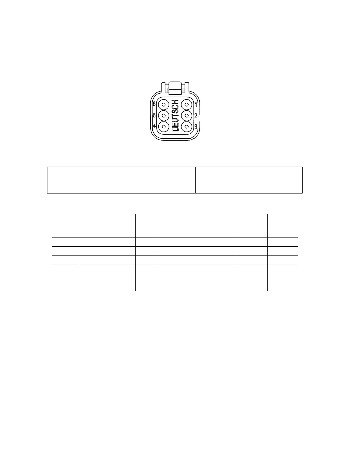
FIGURE 4.1:THE MPIC-SLOPE CONNECTOR (PART NUMBER:DT06-6S)
TABLE 4.1: MPIC-SLOPE CONNECTOR INFORMATION
Reference
Designator Part Number Contacts Mating Part
Number Description
P1
DT06-6S
6
DT04-6P
Deutsch DT Series6 Position Connector
TABLE 4.2: MPIC-SLOPE CONNECTOR PIN OUT INFORMATION
Signal
Pin
Wire
Color I/O Description
Voltage
(nom.
VDC)
Load
(max.
Amp.)
P1-1
White
PWR Input power 5-28VDC 13.6V 1
P1-2
Black
GND Ground 0
P1-3
Orange
I Momentary Switch Input 0
P1-4
Pink
0 External Siren Output 0
P1-5
Blue
I/O CAN Differential Line 0
P1-6
Green
I/O CAN Differential Line 7
2. Momentary Switch Input
If the gesture recognition is not ideal, the MPIC-Slope input can be connected to an external momentary switch. The momentary
switch will act as a substitute for the gesture recognition. Instead of doing a gesture recognition “hold”, the momentary switch can
be pressed and held instead, and for a gesture recognition “swipe”, the momentary switch can be pressed.
3. External Siren Output
The MPIC-Slope output can be connected to an external siren. When the slope goes beyond the audible alarm set point and the
audible alarm is set to “ON”, the MPIC-Slope output will sound the external siren. The tone of the external siren will be an
approximately 60 Hz tone.
4. Installing the MPIC-Slope
The installation of the MPIC-Slope is a simple process. The first step is determining what MPIC-Slope pins will be used on Table 4.2.
The only wires absolutely needed are the PWR and GND wires. You can determine if you need the momentary switch input, 3rd pin,
and the external siren output, 4th wire, by reading the two sections above. The next step is to create the mating connector harness

13
(DT04-6P). If an external siren will be used, connect it to the mating connector harness, and if a momentary switch input will be
used, connect it to the mating connector harness. Next, install the mating connector harness.
Unless there is already a 2” hole that the MPIC-Slope firmly fits into, the next step is to cutout the hole for the MPIC-Slope using the
cutout template. Make sure to use proper safety equipment and tools to make the cutout.
The next step is to connect the installed mating connector (DT04-6P) to the connector on the MPIC-Slope’s connector (DT06-6S).
To finish the install, press fit the MPIC-Slope into the cutout. If desired, peal the adhesive backing from the rear of the gauge prior to
installation to prevent un-intended rotation.
Power Up
1. Splash Screen
Not only does the splash screen show Riverside’s logo, it also shows the module’s firmware version number. The splash screen is
only shown for 2 seconds on power up.
2. Set Point Screen
The set point screen describes how the MPIC-Slope is configured. It shows the audible set point, the visual set point, and the speaker
image will change when the sound is on or off. The set point screen is also only shown for 2 seconds on power up.
3. Home Screen
After the splash screen and the set point screen, the home screen is displayed on power up. The home screen is the main screen of
the MPIC-Slope that displays the pitch, roll, slope, and/or grade. The home screen can be changed through the settings menu, which
can be seen in the Home Screen Selection section in Chapter 4.
Firmware Version Number
Audible Warning Set Point
Visual Warning Set point
Audible On/Off Graphic

14
Safety Notifications
The MPIC-Slope contains safety features that help prevent applications from going on too high of a slope. Two of the safety features
include the audible alarm and the visual warning. These warnings will be triggered when the slope is equal to, or greater than, their
set points. The set points can be configured for both warnings in the settings menu. The audible alarm can be connected to an
external siren. The visual warning will flash between the warning screen and the home screen, and the warning screen looks like
this:
Note: The warnings will be disabled while in the settings menu.
Navigation
1. Gesture Recognition Sensor Area
The gesture recognition sensor area contains the three windows on the left hand side of the MPIC-Slope. Every gesture that is
performed should be performed over all 3 gesture windows.
Gesture Sensor Area
15
2. Gesture Recognition “Hold”
To perform a gesture recognition “Hold”, the user has to put their hand over the three gesture windows and hold it there for a
certain length of time like in figure 4.2. The orientation of your hand does not affect it as long as all 3 gesture windows are covered.
FIGURE 4.2:WHERE TO PLACE YOUR HAND FOR A GESTURE RECOGNITION “HOLD”.
Note: Your hand isn’t required for a gesture recognition “Hold”. It can be anything that is placed over all 3 gesture windows.
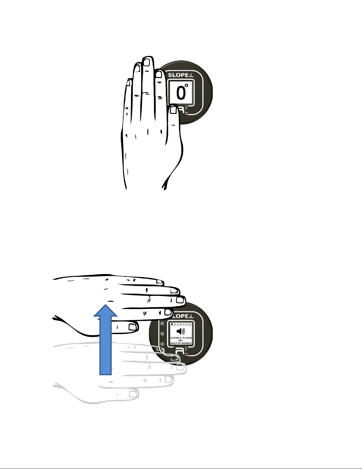
3. Gesture Recognition “Swipe”
To perform a gesture recognition “Swipe”, the user has to guide their hand from the bottom of the MPIC-Slope to the top making
sure they went over every gesture window on the way up like in figure 4.3. This motion should be in a slow, steady pace. The
orientation of your hand does not affect the “Swipe”.
FIGURE 4.3:HOW TO PERFORM A GESTURE RECOGNITION “SWIPE”.
Note: Your hand is not required for a gesture recognition “Swipe”.

16
Configuration
1. Factory Configuration
The MPIC-Slope comes from the factory with a default configuration as seen in Table 4.3.
TABLE 4.3: MPIC-SLOPE FACTORY CONFIGURATION SETTINGS
H
OME
S
CREEN
V
ISUAL
S
ET
P
OINT
A
UDIBLE
S
ET
P
OINT
A
UDIBLE
A
LARM
C
ALIBRATION
F
ACTORY
D
EFAULT
(L
ARGE
S
LOPE
)
20
20
ON
0
(F
LAT DISPLAY UP
)
2. Settings Menu Overview
The settings menu allows you to configure the MPIC-Slope to be your own device. The settings menu contains a location bar at the
top, which is 7 squares that represent the 7 settings screens. The filled in square is your current location in the settings menu. The
settings menu also uses inactivity timers that will bring the MPIC-Slope back to the home screen. As an example of a settings menu
screen, the 1st screen is the audible enable screen:
3. Entering the Settings Menu
In order to enter the settings menu, the user has to perform a gesture recognition “Hold” for approximately 8 seconds. The screen
will change from the home screen to the settings menu.
Audible Alarm Enable Graphic
Settings Menu Location Bar
Menu Instructions

17
4. Navigating the Settings Menu
In order to navigate the settings menu, the user has to perform gesture recognition “Swipes”. The screen should cycle from one
settings screen to another. As you navigate the settings menu, the settings menu location bar will update depending on which
screen the MPIC-Slope is located on. The settings menu wraps around, so if the MPIC-Slope is on the last screen of the settings menu
and perform a gesture recognition “Swipe”, it will return to the first screen of the settings menu.
18
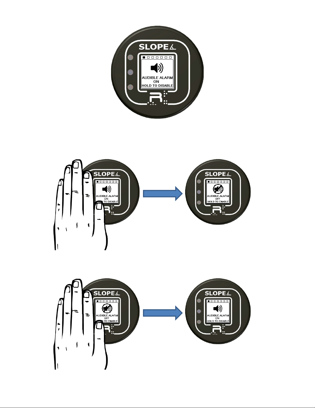
5. Audible Alarm Enable
The audible alarm setting is located on the 1st page of the settings menu. If the audible alarm is disabled, the external siren will not
go off even if the slope reaches the audible alarm set point.
To disable the audible alarm, perform a gesture recognition “Hold” for 3 seconds.
To enable the audible alarm, perform a gesture recognition “Hold for 3 seconds.

19
6. Audible Alarm Set Point
The audible alarm set point setting is located on the 2nd page of the settings menu. The set point defines the amount of slope that is
required to sound the siren. The audible alarm will only be on when the home screen is being displayed. The range of the audible
alarm set point can be from 5-30° in 5° increments.
To change the audible alarm set point:
1. Perform a gesture recognition “Hold” for 3 seconds or until the set point number starts flashing.
a. If the user changes their mind, wait for the MPIC-Slope to time out in 30 seconds to go back in the settings
menu.

20
2. The user will have to do a gesture recognition “Swipe” until the set point is the wanted value.
3. To save the set point value, perform a gesture recognition “Hold” for 3 seconds or until the number stops flashing.
This manual suits for next models
1
Table of contents


