RIVIAN PT00401761 User manual
JUNE 2022
FLEET AC DISPENSER WITH 18 FT CABLE
Installation Guide
PRODUCT NUMBER PT00401761

© 2021-2022 Rivian Automotive, LLC. All rights reserved.
All information in this document and all Rivian software is
subject to copyright and other intellectual property rights of
Rivian Automotive, LLC, its affiliates, or its licensors. This
material may not be modified, reproduced, or copied, in whole
or in part, without the prior written permission of Rivian
Automotive, LLC, its affiliates, or its licensors. Unless indicated
otherwise, all trademarks are owned and registered by Rivian
Automotive, LLC, its affiliates, or its licensors in the United
States and/or other countries. Please visit
https://www.rivian.com/legal/brand for Rivian's trademarks and
service marks.
Software embedded or accessed by the vehicle may utilize
open source software. Please visit
https://www.rivian.com/legal/open-source for more
information.

Contents
Important Safety Instructions 4
SAVE THESE INSTRUCTIONS 4
Precautions 4
Safety Symbols on Hardware Labels 8
Introduction 9
Identify Parts 9
Tools and Equipment 10
Remove the Faceplate 11
Install the SIM Card 12
Install the Dispenser 12
On a Rivian Gantry 12
On a Rivian Pedestal 12
On a Wall 15
Set the Operating Current 23
Connect Conductors 24
Install the Faceplate 25
Wall Installation Only - Wrap and Dock the Cable 26
Complete the Installation 26
Light Bar States 27
Troubleshooting 28
Specifications 29
Supplemental Information for Electrical Service Wiring 31
240V Split-Phase System 31
208V Three-Phase Wye-Connected 32
240V Three-Phase Delta-Connected 33
FCC Interference Statement 34
RF Exposure Information 34
Industry Canada Statement 35
Radiation Exposure Statement 35
Déclaration d'exposition aux radiations 35
Customer Service 37

Important Safety Instructions
SAVE THESE INSTRUCTIONS
DANGER
Read all the instructions before installing the Rivian
FleetACDispenser. Follow the safety instructions and
warnings in this guide when installing the FleetACDispenser.
Failure to do so may result in fire, electrical shock, serious
injury, or death.
PRECAUTIONS
The following safety symbols are used in this document.
DANGER
Risk of electric shock
DANGER
Risk of personal injury
CAUTION
Risk of damage to equipment
Risk of Electrical Shock
DANGER
lImproper connection of the equipment grounding conductor
can result in a risk of electric shock. Check with a qualified
electrician or service person if you are in doubt as to whether
the product is properly grounded.
lDo not touch live electrical parts. Incorrect connections may
cause electric shock.
4

lNo user serviceable parts inside. Refer servicing to qualified
service personnel.
lDo not put fingers into the coupler.
lDo not use this equipment if the flexible power cord or cable
is frayed, has broken insulation, or any other signs of damage.
lDo not use this equipment if the enclosure or the coupler
is broken, cracked, open, or shows any other indication of
damage.
lDo not allow unsupervised children in the area during
installation of the FleetACDispenser.
lBefore connecting the FleetACDispenser to a power supply,
check that the power supply voltage and current rating
corresponds with the power supply details shown on the
product ratinglabel.
lUse appropriate protection when connecting to a main
switchboard.
lGround the FleetACDispenser through a permanent wiring
system using the equipment grounding conductor.
lTo reduce the risk of fire, connect only to a circuit provided
with no more than 60 amperes maximum branch circuit
over-current protection in accordance with the National
Electrical Code, ANSI/NFPA 70, and the Canadian Electrical
Code, Part I, C22.2.
lWhen a breaker smaller than 60 amperes is used, ensure
that the conductor sizes used comply with the minimum
sizes prescribed by national and local electrical codes and
standards.
5

Risk of Personal Injury
DANGER
lDisconnect the power supply before installing or repairing
the FleetACDispenser. Failure to do so may result in
physical injury or damage to the power supply system and
the FleetACDispenser.
lKeep any packing materials away from children. These
materials are a potential source of danger, and can cause
suffocation.
lOnly a licensed electrician should perform this installation in
accordance with the provisions of national electrical codes
and standards.
6

Risk of Damage to Equipment
CAUTION
lUse anti-static gloves, wrist bands connected to ground, and
insulated tools for installation and removal of the faceplate.
lDo not operate this equipment in temperatures outside its
operating range of -30°C to +50°C (-22°F to +122°F).
lStore this equipment in a clean dry location between -40°C
and +80°C (-40°F to +176°F).
lDo not use extender cables to increase the length of the
charging cable.
lIf this unit is installed outdoors, the components and fittings
must be rated for outdoor installation. The outlet must be
installed properly to maintain the proper NEMA rating of
the enclosure.
lAvoid direct hand contact with components on the
networkboard.
lFor storage/shipping of the front panel or network board, use
a bubble wrap bag with ESD (electrostatic discharge)
protection.
lRivian does not recommend using a GFCI breaker since the
FleetACDispenser has charging circuit interrupting device
(CCID20) protection. Using a GFCI breaker in the panel can
cause nuisance tripping. If local codes require a GFCI breaker
for plug-in installation, Rivian recommends a hardwire
installation.
7
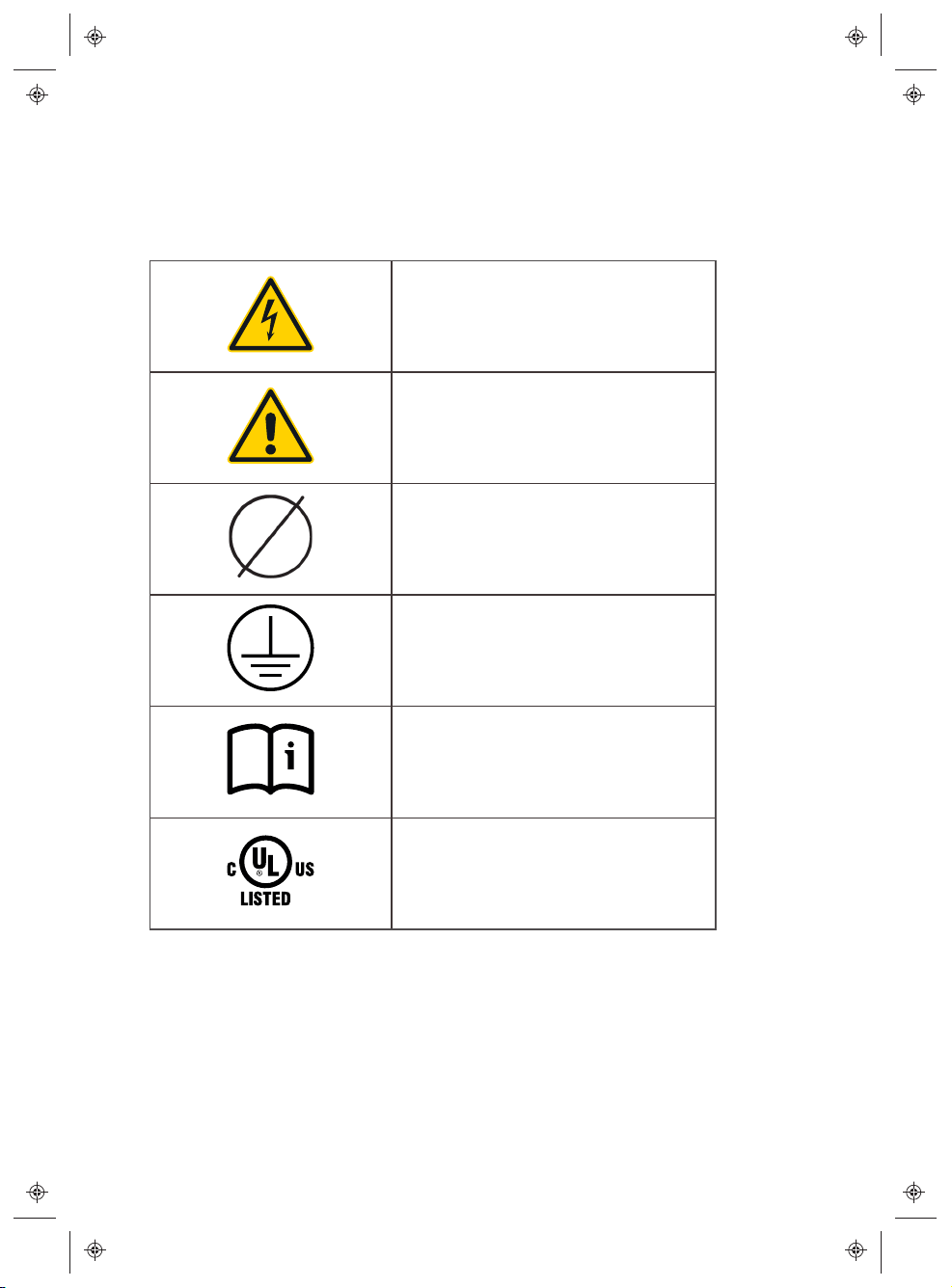
SAFETY SYMBOLS ON HARDWARE LABELS
The following safety symbols may appear on labels located on hardware used
in this installation.
Risk of Electric Shock
Danger
Phase
Equipment Ground
Instruction Manual
ULLogo
8

Introduction
This document provides installation instructions for the FleetACDispenser
with 18 ft cable on a Rivianpedestal, gantry, or wall.
Identify Parts
1. FleetACDispenser
2. Mounting plate (wall
installationonly)
3. Four T20 anchor screws
(wallinstallation only)
4. Two 13 mm M4 Phillips screws
5. Micro SIM (3FF) card
6. T20 Security bit
9

Tools and Equipment
Required Optional (Wall Installation
Only)
#2 Phillips screwdriver Hole saw
Security T20 Torx screwdriver Stud finder
Flathead screwdriver, 7/32 in width Level
Adjustable torque screwdriver,
10in-lb to 40 in-lb
Multimeter
10
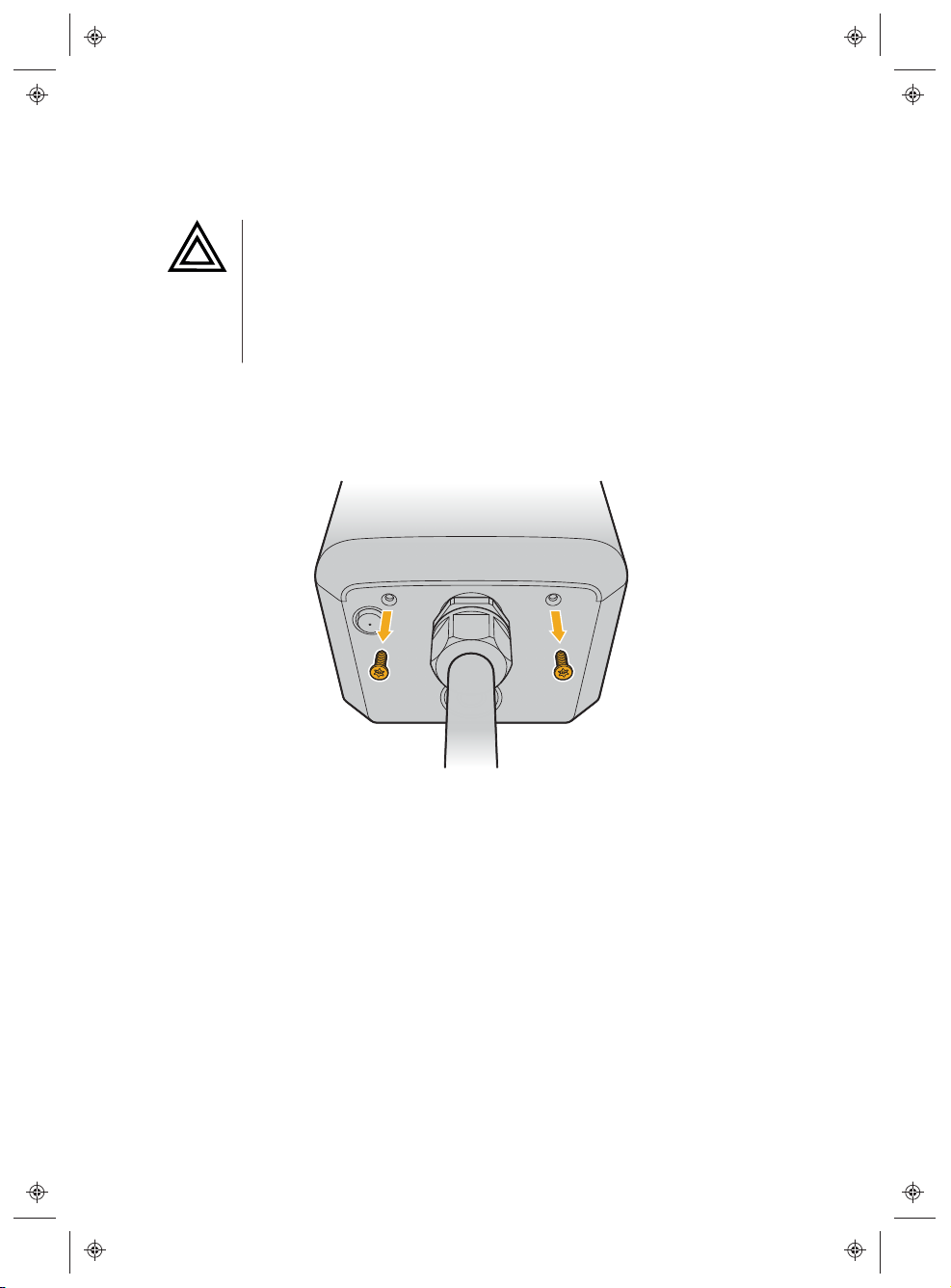
Remove the Faceplate
CAUTION
lUse anti-static gloves, wrist bands connected to ground, and
insulated tools for installation and removal of the faceplate.
lAvoid direct hand contact with components on the
networkboard.
1. Remove the two Security T20 Torx screws on the bottom of the
FleetACDispenser.
2. Push the faceplate up and remove it.
11
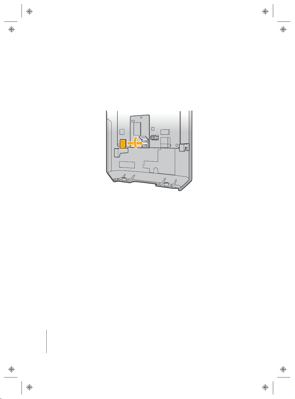
Install the SIM Card
1. Locate the SIM card socket on the interior of the faceplate.
2. Slide the SIMcard socket cover upward and outward to open it.
3. Insert the Micro SIM (3FF) card into the socket.
4. Close the socket to lock it.
Install the Dispenser
lOn a gantry (see below).
lOn a pedestal (page 12).
lOn a wall (page 15).
ON A RIVIAN GANTRY
Refer to the Rivian gantry installation guide for instructions on how to install
the Fleet AC Dispenser on a Rivian gantry.
ON A RIVIAN PEDESTAL
NOTE
Before mounting the FleetACDispenser, refer to the Rivian pedestal
installation guide for instructions on how to install the pedestal.
12
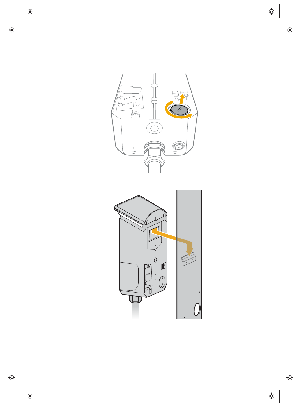
Attach the Dispenser to the Pedestal
1. Remove the wire entry cover from the rear of the FleetACDispenser by
turning it counterclockwise.
2. Hang the FleetACDispenser on the mount hook located on the pedestal.
13
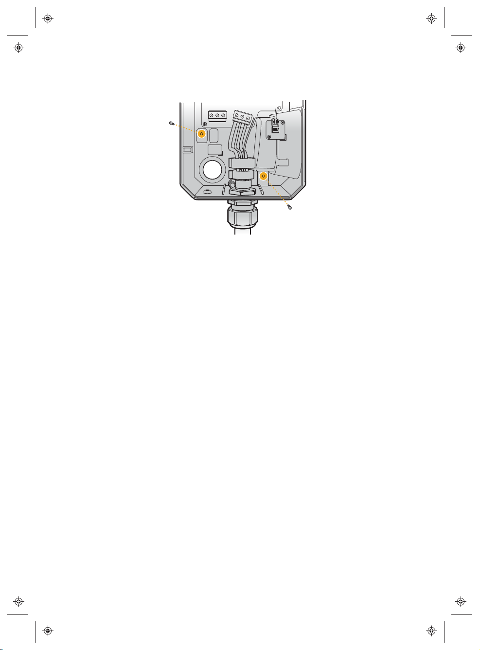
3. Using a #2 Phillips screwdriver, install the two 13 mm long M4 screws
through the interior of the FleetACDispenser into the pedestal.
4. Torque each screw to 12 in-lb (1.36 N·m).
5. Place the cable plug in the dock on the pedestal.
14
ON A WALL
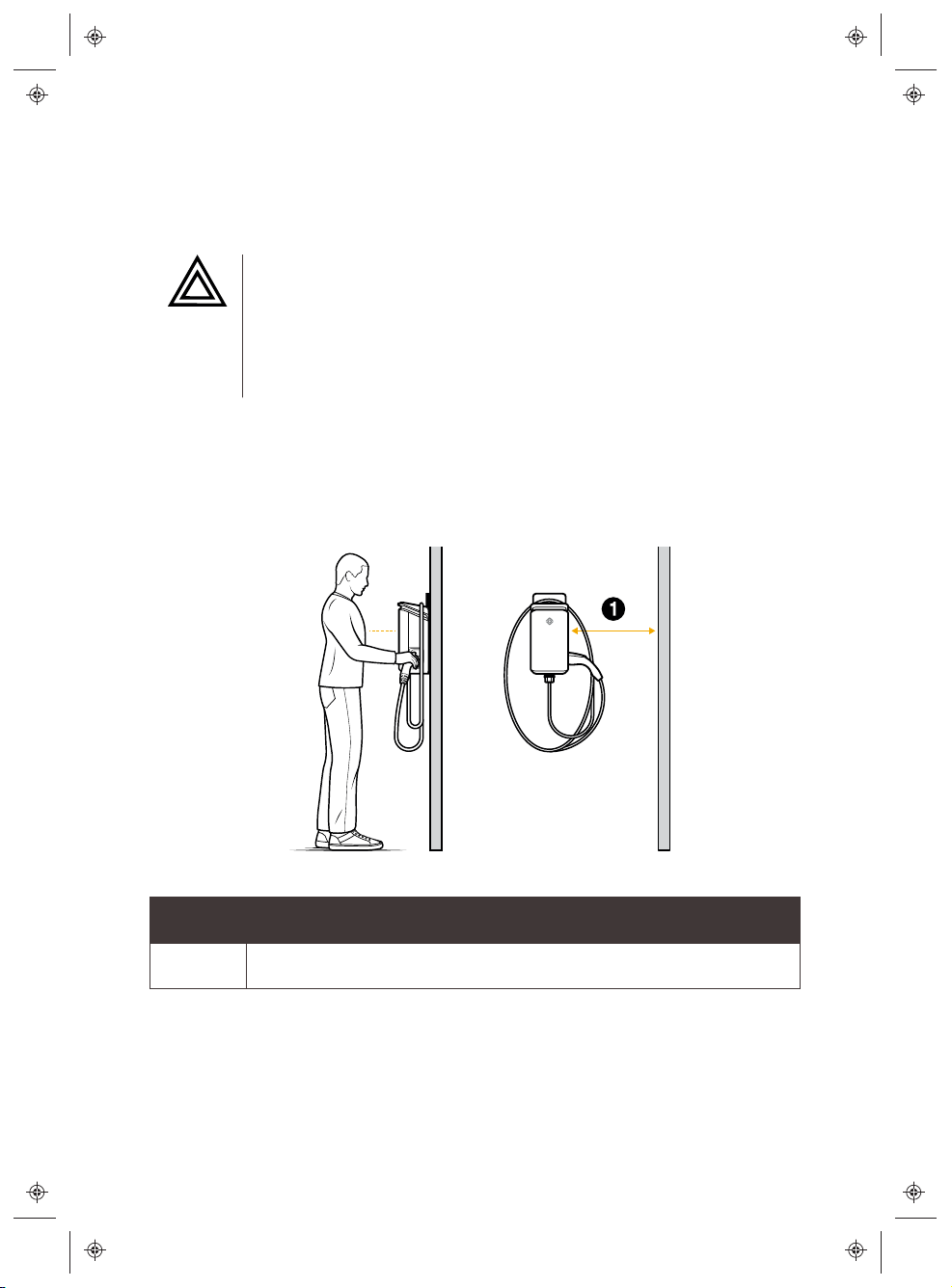
Select an Installation Location
CAUTION
lFor indoor installations, install the FleetACDispenser at least
18 in (45.7 cm) from the ground to bottom ofdispenser.
lFor outdoor installations, install the FleetACDispenser at
least 24 in (61 cm) from the ground to bottom ofdispenser.
For ease of use, install the FleetACDispenser around chest height, within
easy cable reach of the vehicle charge port, and with at least 12 in (30.5 cm)
ofclearance on the right side to accommodate coupler docking and
cablemanagement.
Item Description
1 At least 12 in (30.5 cm)
15

Remove the Holster Cover Plate
Use a flathead screwdriver to pop the holster plate cover off of the side of
the FleetACDispenser.
16

Install the Holster Assembly
1. Insert the holster assembly into the opening on the side of the
FleetACDispenser, aligning the two screw holes in the holster assembly
with the screw holes in the interior of the FleetACDispenser.
2. Use a Torx T20 Security driver to install the two Torx T20 head screws.
3. Torque each screw to 1.47 N·m.
17

Attach the Mounting Plate
NOTE
lFeed conduit only from the bottom when mounting the
FleetACDispenser at an outdoor site.
lWhen installing on a concrete wall, select a fastener suitable for
installation on concrete or stucco. Do not use the T20 fasteners
provided with the product.
To a Concrete Wall
1. With the flat side of the mounting plate
against the wall, and the large hole
positioned in the lower-left, installa
fastener in each of the four
locationsshown.
2. Use a level to confirm the plate is level.
3. Tighten the screws to secure the
mounting plate to the wall. Ensure that
both the screw and the wall are not
damaged during installation.
18
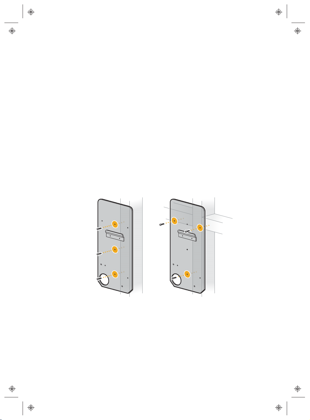
To a Finished Wall Supported by Wooden Studs
1. Use a stud finder to locate the stud(s).
2. With the flat side of the mounting plate against the stud, and the large hole
positioned in the lower-left, install the T20 screws in the locations shown.
lFor a vertical stud, install a screw in each of the three center holes.
lFor a horizontal stud:
a. Select a location where the horizontal and vertical studs meet.
b. Place the three holes in the upper third of the mounting plate
against the horizontal stud and the three holes down the center of
the mounting plate against the vertical stud.
c. Install a screw in each of the two outer holes in the upper third of
the mounting plate.
d. Install a third screw in the lower center location of the
mountingplate.
Vertical Stud Installation Horizontal Stud Installation
3. Tighten the screws in order to attach the mounting plate to the wall.
Ensure that both the screw and the wall are not damaged
duringinstallation.
19

Attach the FleetACDispenser to the Mounting Plate
1. Determine which wire entry point to use in the FleetACDispenser—rear
or bottom—and remove the cover.
lFor indoor installations where wire will run inside the wall, turn the rear
wire entry cover counterclockwise to release it from the
FleetACDispenser.
20
Table of contents
Popular Dispenser manuals by other brands

Fetco
Fetco D041 instructions

Larson Electronics
Larson Electronics XLE-MD-DF-AD-HS-120V instruction manual

MEDICHIEF
MEDICHIEF MDM300W quick start guide

Star Manufacturing
Star Manufacturing Peristaltic Heated Condiment Dispensers... Brochure & specs

WEPA
WEPA Satino 331070 Assembly instructions

ColorMatic
ColorMatic VitoMat III user manual


