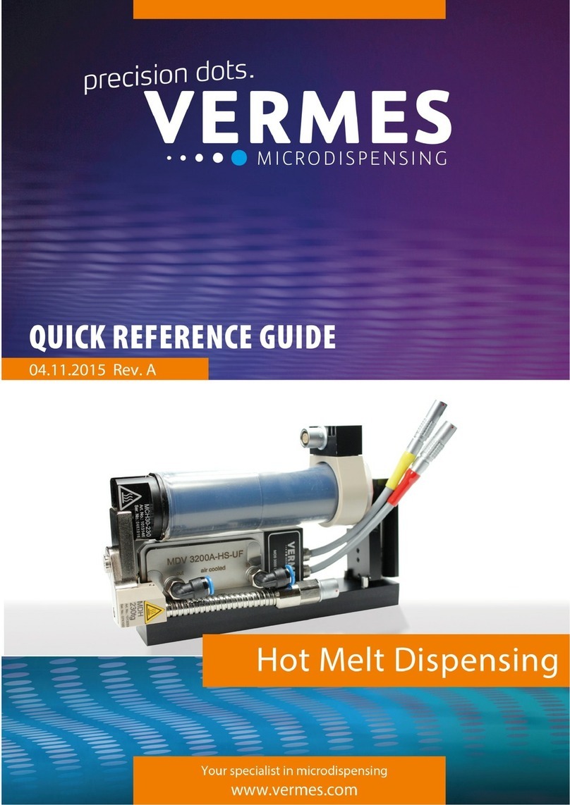
Vermes MDS 3200+ Series User manual


2
VTK-VS-BA-015e-A | User Manual MDS 3200+ Series | Introduction
User Manual for Microdispensing Systems of the MDS 3200+ Series
System
Control Unit
Valve
MDS 3200+-CA
MDC 3200+
MDV 3200A-CA
MDS 3200+-CP
MDC 3200+
MDV 3200A-CP
MDS 3200+-HS
MDC 3200+
MDV 3200A-HS
MDS 3200+-HS-UF
MDC 3200+
MDV 3200A-HS-UF
MDS 3200+
MDC 3200+
MDV 3200A
MDS 3200+-AC
MDC 3200+
MDV 3200A-AC
MDS 3200+-AC-UF
MDC 3200+
MDV 3200A-AC-UF
MDS 3200+F
MDC 3200+
MDV 3200F
MDS 3200+F-HS
MDC 3200+
MDV 3200F-HS

VTK-VS-BA-015e-A | User Manual MDS 3200+ Series | Introduction 3
Content
1Introduction ..............................................................................................6
2General Instructions ..................................................................................7
2.1 How to Use this Manual ........................................................................................................... 7
2.2 Legend ...................................................................................................................................... 7
2.2.1 Danger Symbols........................................................................................................................ 7
2.2.2 Danger Levels ........................................................................................................................... 7
2.2.3 Illustration Convention............................................................................................................. 8
2.2.4 Abbreviations ........................................................................................................................... 8
2.3 Tools ......................................................................................................................................... 9
2.3.1 MDT 301 Universal Tool ........................................................................................................... 9
2.3.2 MDT 302 Nozzle Adjusting Tool ............................................................................................... 9
2.3.3 MDT 303 Nozzle Insert Changing Tool ..................................................................................... 9
2.3.4 MDT 304 Nozzle Insert – Squeezing Out Tool .......................................................................... 9
2.3.5 MDT 310 Tappet Changing Tool ............................................................................................. 10
2.3.6 Hexagon Socket Key Set ......................................................................................................... 10
2.3.7 Torque Wrench....................................................................................................................... 10
2.3.8 Torques (in Nm)...................................................................................................................... 10
3Safety Notes............................................................................................11
3.1 Obligations and Liability ......................................................................................................... 11
3.1.1 Obligations of the Customer .................................................................................................. 11
3.1.2 Obligations of the Operator ................................................................................................... 11
3.2 Residual Risks ......................................................................................................................... 11
3.3 Contracted Use....................................................................................................................... 12
3.4 Specification and Technical Notes.......................................................................................... 13
3.5 Warnings ................................................................................................................................ 13
3.6 Qualifications of Operators and Maintenance Personnel ...................................................... 14
3.7 Protective Equipment and Safety Clothing ............................................................................ 14
4Product Description.................................................................................15
4.1 Control Unit MDC 3200+......................................................................................................... 15
4.1.1 Technical Data ........................................................................................................................ 15
4.1.2 Front Side ............................................................................................................................... 16
4.1.3 Back Side ................................................................................................................................ 17
4.1.4 Function Keys ......................................................................................................................... 18
4.1.5 Menu Structure ...................................................................................................................... 20
4.1.5.1 Main Menu ............................................................................................................................. 21
4.1.5.2 Submenu “Pulse Parameters“ ................................................................................................ 22
4.1.5.3 Submenu “Heater“ ................................................................................................................. 22
4.1.5.4 Submenu “Status“ .................................................................................................................. 23
4.1.5.5 (F) Submenu “F-Valve” ........................................................................................................... 23
4.1.5.6 Submenu “Scenario” .............................................................................................................. 24
4.1.5.7 Submenu “Service-Option” .................................................................................................... 25
4.1.6 Memories of the MDC 3200+.................................................................................................. 25
4.2 Microdispensing Valve MDV .................................................................................................. 26
4.2.1 Composition ........................................................................................................................... 26
4.2.2 Explosion View MDV .............................................................................................................. 28
4.2.3 Specification ........................................................................................................................... 28
4.2.4 Valve Types............................................................................................................................. 29
4.2.5 Special Features of the MDV 3200 series............................................................................... 30

4
VTK-VS-BA-015e-A | User Manual MDS 3200+ Series | Introduction
5Initial Operation ......................................................................................31
5.1 Delivery................................................................................................................................... 31
5.1.1 Unpacking............................................................................................................................... 31
5.1.2 Content................................................................................................................................... 31
5.2 First Assembling of the MDV .................................................................................................. 32
5.3 Installation of the MDS 3200+................................................................................................ 33
5.3.1 Installation of the MDC 3200+................................................................................................ 33
5.3.2 Installation of the Valve as Part of a Machine........................................................................ 34
5.3.3 Wiring of the MDS 3200+........................................................................................................ 34
5.3.3.1 Actuator Cable........................................................................................................................ 34
5.3.3.2 Sensor Cable........................................................................................................................... 35
5.3.3.3 Mains Cable ............................................................................................................................ 36
5.4 The Adjust Process ................................................................................................................. 37
5.4.1 The Adjust............................................................................................................................... 37
5.4.2 (F) MNL Calibration ................................................................................................................ 39
5.4.3 (F) MNL Adjust........................................................................................................................ 40
5.5 Initial Liquid Supply ................................................................................................................ 42
5.6 Removing Air Inclusions from the System.............................................................................. 42
5.7 Parameter Input and Start...................................................................................................... 42
6Operation................................................................................................43
6.1 Triggering a Dispense Sequence............................................................................................. 43
6.2 Dispensing and Positioning of a Multitude of Dots (Modes).................................................. 43
6.3 Parameters for Dispensing Process ........................................................................................ 44
6.4 Minimum and Maximum Parameter Limits ........................................................................... 45
6.5 Input of Values ....................................................................................................................... 46
6.6 Saving Parameter Sets............................................................................................................ 46
6.7 Retrieving Parameter Sets...................................................................................................... 46
6.8 Scenarios ................................................................................................................................ 47
6.8.1 Basics about Scenarios ........................................................................................................... 47
6.8.2Entering Scenarios.................................................................................................................. 47
6.8.3 Scenario Selection with Select Pins ........................................................................................ 48
6.9 Factory Settings ...................................................................................................................... 49
6.10 Dispensing with a Heater ....................................................................................................... 50
6.10.1 Mounting a Heater MDH-230tf .............................................................................................. 51
6.10.2 Heater MDH-230tf and MDC 3200+........................................................................................ 51
6.10.3 The Adjust with Heater MDH-230tf........................................................................................ 52
6.10.4 Demounting the Heater MDH-230tf ...................................................................................... 54
6.11 Switching OFF the MDS .......................................................................................................... 54
7Communication Interfaces.......................................................................55
7.1 Serial Interface RS-232C: 9-Pin Sub-D .................................................................................... 55
7.1.1 Functions Allocated to the Different Pins .............................................................................. 55
7.1.2 RS-232C Commands ............................................................................................................... 56
7.1.2.1 Overview ................................................................................................................................ 57
7.1.2.2 Explanations ........................................................................................................................... 59
7.2 PLC Interface: 15-pin, Sub-D................................................................................................... 79
7.2.1 Pin Functions .......................................................................................................................... 79
7.2.2 Remote Adjust........................................................................................................................ 80
7.2.2.1 What is the Remote Adjust?................................................................................................... 80
7.2.2.2 Advantages............................................................................................................................. 80

VTK-VS-BA-015e-A | User Manual MDS 3200+ Series | Introduction 5
7.2.2.3 Procedure ............................................................................................................................... 80
7.3 AUX socket ............................................................................................................................. 82
8Cleaning ..................................................................................................83
8.1 Preliminary Notes................................................................................................................... 83
8.2 Compatibility between Sealing Material and Selected Medias.............................................. 84
8.3 Heat Resistance of Sealing Materials ..................................................................................... 84
8.4 Cleaning Methods .................................................................................................................. 85
8.4.1 Pre-purifying........................................................................................................................... 85
8.4.2 Rinsing with Purifying Agent .................................................................................................. 86
8.4.3 Dismantling the Valve and Fine Purification .......................................................................... 87
8.4.4 Fine Purification ..................................................................................................................... 90
8.4.5 Assembling of the Fluid Box ................................................................................................... 94
9Maintenance ...........................................................................................98
9.1 Maintenance Indicator ........................................................................................................... 98
9.2 Exchange of Tappet Sealing.................................................................................................... 98
9.3 Maintenance of the Tappet.................................................................................................... 99
9.3.1 The CT-Tappet ........................................................................................................................ 99
9.3.1.1 Demounting............................................................................................................................ 99
9.3.1.2 Installation............................................................................................................................ 100
9.3.1.3 Disassembly and Cleaning .................................................................................................... 100
9.3.1.4 Greasing and Remounting.................................................................................................... 101
9.3.2 TTF- and CTF-Tappet............................................................................................................. 102
9.3.2.1 Demounting.......................................................................................................................... 102
9.3.2.2 Installation............................................................................................................................ 103
9.3.2.3 Disassembly and Cleaning .................................................................................................... 103
9.3.2.4 Greasing and Remounting.................................................................................................... 103
10 Error Messages...................................................................................... 105
11 Transport, Storage and Disposal ............................................................ 111
11.1 Transport .............................................................................................................................. 111
11.2 Storage ................................................................................................................................. 111
11.3 Recycling and Disposal ......................................................................................................... 111
12 Spare Parts and Tools ............................................................................ 112
13 Attachments.......................................................................................... 117
13.1 EC Declaration of Conformity............................................................................................... 117
13.2 Dimensional Drawing MDC 3200+........................................................................................ 118
13.3 Dimensional Drawing MDV 3200A ....................................................................................... 119
13.4 (F) Dimensional Drawings MDV 3200F ................................................................................. 120
13.5 Connection Diagram PLC-Interface ...................................................................................... 122
13.6 Declaration Concerning Decontamination of Shipped Equipment ...................................... 123
14 Index..................................................................................................... 124

6
VTK-VS-BA-015e-A | User Manual MDS 3200+ Series | Introduction
1INTRODUCTION
With a micro dispensing of the MDS 3000 line from Vermes Microdispensing you have bought a
high quality product. Due to the long-standing experience of the team in regards to electronic de-
vices and piezo controls, these products provide highest functionality and reliability.
Thank you very much for your trust in us.
We will now show you how to assemble and use the microdispensing system. In order not to im-
pair the inherent safety concept of the system, procedures described in this manual have to be fol-
lowed consequently during installation and operation.
Read this manual before you start the assembly and always consult it during the use of the
microdispensing system. Start with the chapter “Safety Notes” (see page 11). This will help to pre-
vent any problems for the user or the equipment. In the case of further questions, consult our
Technical Support.
Technical Support VERMES Microdispensing GmbH
Palnkamer Str. 18
83624 Otterfing
Tel.: +49 (0) 80 24 6 44-26
Fax.: +49 (0) 80 24 6 44-19
support@vermes.com
www.vermes.com
Service hours Monday - Friday 9.00 to 17.00 (CET).
The MDS 3000 Product Family
The MDS models are members of the MDS 3000 product family, specialized in most accurate dis-
pensing and designed for flexible use with substances of low, medium and high viscosity (up to
2.000.000 mPas).Applications can be found in the fields of SMT and in the production of electron-
ics, semiconductors and photovoltaic modules and many more.
Each microdispensing system belonging to the MDS 3000 product family is composed of a high pre-
cision valve based on a piezoelectric element (MDV series), a control unit (MDC series) and an op-
tional selectable supply unit.
Due to its compact modular design, the system can be integrated quickly into any existing produc-
tion environment without major preparatory work. A change in the production line (e.g. a modifi-
cation of the liquid to be processed) is easily possible, since all of the dispensing parameters are
adjustable in a large range. Fine-tuning of the sequence is therefore possible at any time. The sys-
tem allows for reproducible proportioning of hundreds of identical single dots (0,3 nl up to
> 200 µl)or beads within a few seconds.
A comprehensive choice of accessories is available, e.g. nozzle inserts, tappets, seals and supply
units, so that the system can easily be adapted to new challenges any time, without giving rise to
major investment.
Valves compatible with MDC 3200+
The base of each Microdispensing System of the MDS 3200+series is the control unit MDC 3200+,
which is then combined with a valve. This can be any valve of the series MDV 3200A or MDV
3200F. This is a complete list:
•MDV 3200F (Order no. 1012887)
•MDV 3200F-HS (Order no. 1013143)
•MDV 3200A-CA (Order no. 1012911)
•MDV 3200A-CP (Order no. 1012852)
•MDV 3200A-HS (Order no. 1012973)
•MDV 3200A-HS-UF (Order no. 1012986)
•MDV 3200A (Order no. 1012270)
•MDV 3200A-AC (Order no. 1012902)
•MDV 3200A-AC-UF (Order no. 1012865)

VTK-VS-BA-015e-A | User Manual MDS 3200+ Series | General Instructions
7
2GENERAL INSTRUCTIONS
This chapter summarizes the content of this manual and contains general information for the user.
An “(F)” in the title marks chapters which are only relevant, if you use an F-valve. Some pictures
might differ slightly from the actual product.
2.1 How to Use this Manual
•Each step of installation, operation and maintenance has to be performed in accordance
with this manual.
•You can find information about safety aspects and an efficient use of the system in the
concerning chapters.
•This manual represents an integral part of the delivery and must be made available to
every user working with this MDS. Always keep it in close vicinity of the machine.
•It must be preserved until the end of the lifetime of the system.
2.2 Legend
2.2.1 Danger Symbols
Pictogram Explanation
Toxic Substances
Danger Originating from Electricity
Explosion Hazard
Potential Danger
Important Note
Information
Refer to User Manual
2.2.2 Danger Levels
Instruction Possible Consequences
DANGER!
The damage is imminent. If the operating procedure is not strictly
observed, this situation may result in death, considerable material
damage or environmental contamination.
WARNING! The danger of death and serious injuring cannot be excluded.
CAUTION! Danger of injuries.
IMPORTANT NOTE! An operating procedure which, if not strictly observed, may result in
damage to the equipment, unexpected interruptions or shutdown.
INFORMATION! Supplementary recommendation for an economical and time-saving
use of the equipment.

8
VTK-VS-BA-015e-A | User Manual MDS 3200+ Series |General Instructions
2.2.3 Illustration Convention
Symbol Explanation
Step 1:
Step 2: The sequence must be followed in correct order
−
Each step of this sequence is mandatory, none of them should be omitted
Direction of movement
•
Lists
[…] Symbol for a key on the keypad
Only concerning valve types MDV 3200F or MDV 3200F-HS (“F-valves”,
for longer sections the end is also marked with a horizontal blue line)
2.2.4 Abbreviations
Abbr.
Full name
CT(F) Ceramics Tappet (flat)
CTK Cleaning Tool Kit
MDC Controller (MicroDispensingControl unit)
MDF Fluid box (MicroDispensingFluid box)
MDS MicroDispensingSystem
MDV Valve (MicroDispensingValve)
MDX Supply unit
MNL Mechanical Needle Lift
NAN Nozzle Adjustment Nut
NAN-fix Nozzle Adjustment Nut with fixation
NI Nozzle Insert
NU Nozzle Unit
NU-fix Nozzle Unit with fixation
PLC Programmable logic controller
POD Point of Dispensing
RTC Realtime Clock
TG Tappet Guidance
TTF Tungsten carbide Tappet, Flat

VTK-VS-BA-015e-A | User Manual MDS 3200+ Series | General Instructions
9
2.3 Tools
The following tools are required to install and to operate the MDS:
•MDT 301 Universal tool (Order no. 1010208)
•MDT 302 Nozzle adjusting tool (Order no.1009289)
•MDT 303 Nozzle insert changing tool (Order no. 1007083)
•MDT 304 Tool for squeezing out nozzle inserts (Order no. 1007085)
•MDT 310 Tappet changing tool (Order no. 1008344)
•MDT 312 Tool for tappet sealing FX (Order no. 1012825)
•Hexagon socket key set (Order no. 1012993)
•Torque Wrench (Order no. 1013298)
When you order tools, always specify the order number of the required item.
IMPORTANT NOTE! (No foreign tools)
Do not use auxiliary tools or foreign products, otherwise damages to the equipment
might be possible.
2.3.1 MDT 301 Universal Tool
The tool MDT 301 comprises two subcomponents screwed to each other:
•“Sealmounter“ with a mandrel to insert and to remove the tappet seal (1.)
•“Adjustment grip“ with a receptacle for the nozzle adjusting nut (2.)
Intended Purpose:
1. Fixing and removing of tappet sealing and tappet centering piece
2. Holding nozzle insert to place it in the tappet guidance (sealmounter)
3. It may also be used to execute the general adjust (alternatively to tool MDT 302)
2.3.2 MDT 302 Nozzle Adjusting Tool
This part has a receptacle for the nozzle adjusting nut and a longer
lever to simplify the general adjust. It can also be used in combination with MDT 310, if a better
leverage is needed. The other end is an open-ended wrench (size 8 mm).
Intended Purpose:
1. Performing the adjust
2. Performing the MNL adjust
3. Fixing the tighting screw to the fluid box
4. Changing of tappet in combination with MDT 310
5. Fixing the Luer-Lock connector
2.3.3 MDT 303 Nozzle Insert Changing Tool
The MDT 303 is required for the exchange of the nozzle insert. The 3 pins of the
MDT 303 grip into the receptacle bores of the tappet guidance in order to un-
screw the tappet guidance from the nozzle adjustment nut.
Intended Purpose:
1. Screwing apart nozzle adjusting nut and tappet guidance when changing
the nozzle insert
2.3.4 MDT 304 Nozzle Insert – Squeezing Out Tool
The diameters of the end pieces of tool MDT 304 are not identical, as each of
them is used for a different purpose.
Intended Purpose:
1. Squeezing out of the tappet sealing between fluid box and actuator (1.)
2. Detaching the nozzle insert from the tappet guidance (2.)

10
VTK-VS-BA-015e-A | User Manual MDS 3200+ Series |General Instructions
2.3.5 MDT 310 Tappet Changing Tool
The MDT 310 features a bore with two studs, serving as a receptacle for the
tappet. When exchanging the tappet, carefully push it into this bore until the
studs latch into the grooves of the tappet centering screw. Then the centering
screw can be inserted or removed by rotating the tool (while applying a light
constant pressure).
Intended Purpose:
1. Removing the present tappet and fixing a new one
2.3.6 Hexagon Socket Key Set
The set includes three socket keys (sizes 2, 2,5 and 3) for hex-screws, with
blades made of hardened steel and ergonomic grips.
Intended Purpose:
1. Mounting and dismounting the fluid box (2)
2. Mounting and dismounting the tappet guard (2)
3. Mounting and dismounting the cartridge holder (2,5)
4. Installation of heaters type MDH-230te (2,5)
5. Fixing of the valve, in-situ (3)
2.3.7 Torque Wrench
A torque wrench allows you to screw tight screws with an exactly set tight-
ening torque. The value can be adjusted continuously at the torque.
Intended Purpose:
1. Screws for fluid box
2. Tappet guidance
3. Tighting screw
4. Fluid box connector Luer-Lock
2.3.8 Torques (in Nm)
Element Torque min. (Nm) Torque max. (Nm) Cross Reference
Screws for fluid box (M 2,5 x 8) 0,8 1 Page 94
Screws for MDC frontplate 0,30 0,40 Page 33
Tighting screw for MDF 3070-CC 1,2 1,4 Page 94
Fluid box connector Luer-Lock 1,0 1,2 Page 94
MNL screw 0,5 0,5 Page 37
Tappet guidance PEEK 0,4 0,6 Page 32
Tappet guidance H 0,8 1 Page 32
Tappet centering screw 1,0 1,4 Pages 100 or 103

VTK-VS-BA-015e-A | User Manual MDS 3200+ Series | Safety Notes
11
3SAFETY NOTES
This chapter summarizes the general safety aspects of the system. Further points to be observed
are emphasized in the corresponding subchapters.
3.1 Obligations and Liability
In order to protect the health of personnel and to avoid unnecessary damage, all of the recom-
mendations of the manufacturer with regards to safety must be explained to every member of the
team taking part in installation, operation or maintenance of the system.
VERMES Microdispensing does not accept any liability for material damages or personal injury orig-
inating from inappropriate use, violation of safety prescriptions, or any procedure inconsistent with
the instructions of this manual. The general rules for prevention of accidents as well as local envi-
ronmental regulations must be in place and thoroughly followed by the personnel.
3.1.1 Obligations of the Customer
In view of a trouble-free operation of the microdispensing system, the customer has to select his
personnel carefully:
•Unauthorized use must be prevented. Persons ignoring the fundamental requirements of
industrial safety, environmental protection and prevention of accidents are not allowed
to work with the system.
•New operators must correspondingly be instructed and trained, so that they can under-
stand and put into practice the instructions of this manual. For certain measures, a par-
ticular qualification may be required.
•The manual must remain accessible at any time.
3.1.2 Obligations of the Operator
All persons in charge of the system must:
•Continuously respect the general rules for prevention of accidents.
•Be aware of the safety notes of this manual. This is necessary also for operators trained
by the manufacturer or experienced in work with similar systems.
•Consult the manufacturer in any case of doubt. Applications beyond the scope of the
specification and improvised repair work must be avoided.
3.2 Residual Risks
The microdispensing system has been developed and designed with the common requirements of
safety in mind, and corresponds to the current state of technology. In the delivered layout, it com-
plies with the following regulations and directives:
•2006/42/EC Machinery Directive
•2006/95/EC Low Voltage Directive
•2004/108/EC Electromagnetic Compatibility
•2002/95/EC Restriction of the Use of Certain Hazardous Substances in Electrical and Elec-
tronic Equipment (RoHS 2003-01-27)
•DIN EN 61010-1 (VDE 0411) Safety Requirements for Electrical Equipment for Measure-
ment, Control and Laboratory
•DIN EN ISO 12100-1 and DIN EN ISO 12100-2 Safety of the Machinery, Fundamental Terms
•DIN EN 60204-1 (VDE 0113) Safety of the Machinery, Electric Installations of Machinery,
Part 1 General Requirements
•DIN EN 982 Safety Requirements for Fluid Power Systems and their Components – Hydraulics.

12
VTK-VS-BA-015e-A | User Manual MDS 3200+ Series |Safety Notes
Despite this comprehensive inherent safety structure, the operation of the microdispensing system
MDS 3200+may entail danger
•For the health of the operator or a third party,
•For the system itself,
•Or give rise to another material damage.
Therefore the use has strictly to be limited:
•To the intended application,
•To a state in which the technical safety of the system can be guaranteed (i.e. it is strictly
forbidden to start or continue the operation whenever a defect has become obvious).
Problems with a potential to impair safety aspects must immediately be solved. For this reason, it
is imperative that this manual remains accessible any time without delay. In an emergency situa-
tion, a short reaction time may be crucial.
If the system is transmitted to any other department or institution, it must be accompanied by
this manual.
3.3 Contracted Use
The system MDS 3200+has been designed for ultra-precise contactless dispensing of fluids in a
large range of viscosity (up to 2.000.000 mPas), in unfilled or filled state (also with abrasive extend-
ers), to be operated in a conveniently equipped industrial or laboratory environment.
Deviations from the instructions of this manual must explicitly be authorized by the manufacturer
(in writing); otherwise his liability with regard to the guarantee becomes null and void.
This includes:
•Extensions and changes of design
•Modifications of the system, or spare parts not recommended by the manufacturer
•Inappropriate material selection (lack of compatibility between parts and dispensed fluids)
•Operation with damaged parts or after improvised repair
•Dispensing of fluids able to affect the functionality of the system (in case of doubt, con-
sult manufacturer)
•Manipulation or absence of integrated safety devices or sealings
•Repair by persons or enterprises not authorized by the manufacturer
•Operation beyond the scope of the specification
•Auxiliary equipment not recommended by the manufacturer
•The system is not admitted for applications in hazardous locations (ATEX zones)
In no event shall we be liable under our guarantee or any other provision of the agreement for
damages resulting from a violation of the instructions of this manual.
For further questions concerning current applications and modifications of the system with respect
to new requirements, contact the manufacturer, the responsible sales partner or the Technical
Support.

VTK-VS-BA-015e-A | User Manual MDS 3200+ Series | Safety Notes
13
3.4 Specification and Technical Notes
•The system is designed for interior use only. Maximum altitude: 2000 m.
•The relative air humidity shall not surpass 80 % rH at 31 °C or 50 % rH at 50 °C (with a lin-
ear decline).
•Temperature: 10 °C till 50 °C
•Admissible mains voltage fluctuations: Within the range of ± 10 % of rated voltage.
•Transient overvoltage tolerated acc. to IEC 60364-4-443, max. degree of soiling: 2
•Mains cables must feature a protective conductor. In the case of cables not delivered
by Vermes Microdispensing, the guarantee for the MDS 3200+is valid only up from the
interface.
•Power outlets must comply with common safety prescriptions.
•During the application, sufficient air circulation must be guaranteed.
For further details, refer to Installation chapter (page 33).
•Cooling is achieved by compressed air, free of fine particles, dust, oil and condensate,
quality classes 1, 3, 2 acc. to DIN/ISO 8573-1.
−Solid particles: 0,1 µm max., admissible density: 0,1 mg/m³ = Quality class 1
−Water content: max. pressure dew point -20 °C, water content 0,88 g/m³ = Quality class 3
−Residual oil: 0,1 mg/m³ max. = Quality class 2
3.5 Warnings
•Handle the mains cables correctly: Always seize the cable at the plug. Never touch it with
wet hands.
•The cable should never be squeezed or kinked. Never place the instrumentation (or any
other object)on the cable.
•Damaged cables may give rise to fire and danger caused by electricity. Inspect them vis-
ually in regular intervals. Damaged parts should be exchanged at once.
•In the case of a major disturbance, disconnect the equipment immediately from the
mains.
•Spare parts not delivered or recommended by the manufacturer could affect the inher-
ent safety of the system. The same problem arises, if the customer attempts to process
substances not admitted for the dispensing system.
•Unqualified repair work often causes major damages, sometimes even personal injuries.
Therefore repair is reserved to our Technical Support and authorized subcontractors.
•Before removing the actuator and sensor cable, the system must be switched OFF.
•For longer interruptions, switch OFF the control unit.
•Before disconnecting the MDC 3200+from the mains, switch it OFF.
•Repeatedly switching ON and OFF the equipment may reduce the lifetime of the power unit.
•Before charging the fluid system with an aggressive, reactive or toxic substance, it must
be verified that it is compatible with all of the contacting components inside the system.
•The supply pressure at the cartridge or in the pressure tank of 7 bar resp. 100 bar (accord-
ing to the system configuration) should never be exceeded.
•If you use the MDV with a heater for the nozzle unit, the temperature in that area can
reach up to 120 °C. Do not touch it during operations and afterwards only once it had
enough time to cool down.
•When cleaning the components in contact with the transported substance, the device
should be placed in a safe and stable position, without being subjected to vibrations.
•To clean the actuator, a cloth not fluffy and lightly moistened (e.g. by Isopropanol)is rec-
ommended. During the cleaning procedure, no liquid should penetrate into the actuator
itself (e.g. through the plug).

14
VTK-VS-BA-015e-A | User Manual MDS 3200+ Series |Safety Notes
•The MDV 3200 series is designed according to the Normally Open principle. Therefore
the valve is normally open and the transported liquid can flow. Before switching OFF the
microdispenser, do not forget to lower the supply pressure to atmospheric pressure.
3.6 Qualifications of Operators and Maintenance Personnel
The microdispensing system together with all attached accessories should only be used by compe-
tent personnel with an adequate qualification. They must know and understand the content of the
manual. We do suppose that the department head is aware of possible dangers, and correspond-
ingly assigns the tasks to persons able to execute their work in a responsible manner.
According to DIN VDE 0105 and IEC 364 qualified personnel refers to members of the team with a
sufficient knowledge of relevant norms, directives and rules for prevention of accidents. They need
the qualification and experience necessary, so that they are in a position to realize and to prevent
possible dangers already at an early stage. Knowledge in First Aid and a direct contact to the local
emergency units is required as well.
3.7 Protective Equipment and Safety Clothing
You should always wear suitable protective equipment, whenever handling or dispensing aggres-
sive, reactive or toxic substances. The same is valid in the presence of a high supply pressure.
This may comprise:
•Safety glasses
•A breathing apparatus
•An overall and gloves resistant to the corresponding chemical fluid
When you work in the direct vicinity of the MDS for a prolonged period, you
should also wear ear protection.

VTK-VS-BA-015e-A | User Manual MDS 3200+ Series | Product Description
15
4PRODUCT DESCRIPTION
This chapter contains relevant information about the control unit MDC 3200+and the respective
valve. It describes the menu structure, keypad and functions of the control unit, as well as the
structure and the hardware configuration of the valve itself. Most features are comparable for all
types of compatible valves. The few cases, where the F-valves differ from the rest, are marked by
an F-symbol in the margins (see chapter 2.2.3).
4.1 Control Unit MDC 3200+
4.1.1 Technical Data
Dimensions 128 mm H x 102 mm W x 173 mm D (w/o cable)
128 mm H x 102 mm W x 185 mm D (with cable)
3 HE x 20 TE
Weight ca. 1500 g
Supply Voltage 110/230 V AC/DC
Supply Frequency 50/60 Hz
Current Consumption 900 mA max.
During start-up, this value may be increased by a
factor of 5 (start-up peak).
Recommended fuse: 16 A for 240 V resp. 110 V
Operating Temperature 0 °C to 50 °C
Air Humidity 35 % till 80 % rH
Casing Type Plug-in case for 19“ rack
Color of Casing Black, with lighter front plate
Ventilation Convection
Internal storage locations: 10
Display lines 2 lines with 16 characters each
Display color White with background lighting
Keypad 12 softkeys
Color of keys Blue, beige
Control lamps (Front) 1x Heating circuit (red)
1x Service request (red)
1x Adjust OK (green)
1x Adjust not OK (red)
Control lamps (Back)1x Illuminated power lamp
Plug contacts (Back)1x Mains plug (110/240 V AC)
1x 9 pin Sub-D RS-232C
1x 15 pin Sub-D PLC
1x Aux-output 24V
1x Sensor socket
1x Actuator socket
1x Socket for heating
1x Thermocouple socket

16
VTK-VS-BA-015e-A | User Manual MDS 3200+ Series |Product Description
4.1.2 Front Side
LC display (two lines with sixteen characters each):
Data, service intervals and menu options are shown in the two lines of the illuminated LC display.
The current menu option appears in the upper line, whereas the lower line contains the current
parameter value for dispensing, according to numerical data to be modified.
Keypad with twelve soft keys:
Menu options to control the system are selected by means of these keys.
Details for changing parameters etc. are explained in chapter 4.1.4, page 18.
Control lamp for service request:
As soon as this lamp lights up, it is recommended to return the valve to the manufacturer (or li-
censed subcontractor) for regular periodic maintenance.
Control lamps for adjust:
The adjust for the valve is internally monitored; the result is visualized during the adjust by means of
these two control lamps.
Green: The value is OK and can be confirmed by [enter].
Red: The value is too high and must be lowered according to the instructions of this manual, see page 37.
Control lamp for status of heating:
This red LED indicates the activity of the heating. ON, heating activated, otherwise OFF.

VTK-VS-BA-015e-A | User Manual MDS 3200+ Series | Product Description
17
4.1.3 Back Side
Thermocouple socket:
This element is intended for connection of thermocouples “Type K“.
Mains switch:
By means of this illuminated switch, the unit is switched ON and OFF.
AUX socket:
This connector can be used for supply of an external device (e.g. an optocoupler) or to control cer-
tain parameter setups or scenarios (see chapter 6.8.3). It is one of the three interfaces of the MDC
3200+(see chapter 7.3 for the pin assignments).
Socket for heating:
The heater cable has to be connected here.
RS-232C Interface (9-pin):
Since the system offers the possibility of external programming of dispensing parameters via PC, a
local RS-232C is integrated to receive the data. For the communication protocol, refer to page 55.
Sensor socket:
For the connection of the sensor cable.
Actuator socket:
For the connection of the actuator cable.
PLC Interface (15-pin):
Different inputs and outputs may be connected. For the communication protocol, refer to page 79.
Shackle for the mains cable:
Secures the mains cable against slipping off.
Mains connector:
Connects the control unit to power supply.

18
VTK-VS-BA-015e-A | User Manual MDS 3200+ Series |Product Description
4.1.4 Function Keys
Function Key Function
Manual Trigger Key
Pressing the [trig]-key instantaneously launches a dispensing procedure ac-
cording to the selected parameter settings.
The [save]-key opens the menu for storing current parameters. Ten storage
locations are available for distinct configuration sets. Each set contains values
for pulse parameters and the settings for heating and key interlock.
Select the desired storage location by means of arrow keys.
Press to Confirm.
Press to cancel without saving the selection.
Parameter sets saved in the internal memory can be retrieved any time with
the [recall]-key.
Use the arrow keys to select one of the ten internal
storage locations.
Press to confirm the selection.
Press to abort.
The [adj]-key is used to start the adjust (see page 37). It is required during
each initial operation and after an exchange of the nozzle unit.
With this procedure, the position of the nozzle insert with respect to
the tappet is preselected.
Pressing the [enter]-key confirms the menu selection and opens the corre-
sponding submenu.
... or ...
The entry of a value is confirmed, and the screen changes to the next-higher
menu level.
Pressing the [esc]-key aborts the current action, values just entered are delet-
ed. The next-higher menu level opens.
... or ...
Direct access to the next-higher menu level.
Access to the next-higher menu level.
... or ...
Increasing of a numerical value.
Access to the next-lower menu level.
... or ...
Reduction of a numerical value.

VTK-VS-BA-015e-A | User Manual MDS 3200+ Series | Product Description
19
The screen moves one menu step back.
... or ...
The cursor is shifted one position to the left.
... or ...
A parameter is modified.
The screen moves one menu step ahead.
... or ...
The cursor is shifted one position to the right.
... or ...
A parameter is modified.
This key opens the valve, taking into consideration the current values for “Ris-
ing” and “Falling”. The valve remains opened until the key is released. Maxi-
mum length: 2 min. Then the valve closes automatically in order to protect
the actuator.
If you start the control unit, while holding the [F2]-key, you are given the op-
tion to format the EEPROM. With [enter] you agree, with [esc] you skip this
point and reach the main menu just as normal. This function will only be nec-
essary in exceptional cases.
IMPORTANT INFORMATION!
Settings for Scenarios will not be reset back to the factory settings. That is
only possible with the options “Scenario” and “Reset ALL” after entering the
service code 1000 (s. chapter 4.1.5.7).

20
VTK-VS-BA-015e-A | User Manual MDS 3200+ Series |Product Description
4.1.5 Menu Structure
The main menu of the control unit MDC 3200+contains 6 submenus: “Pulse Parameters“, “Heat-
ing“, “Status“, “F-Valve”, “Scenario” and “Service-Option”. With the [enter] key you can reach the
level of the submenus. There you can switch around with the keys [arrow right] and [arrow left].
Another option from the main menu is to use [arrow right] or [arrow left], which allows you to
gather some information about the system, like maintenance situation or ID numbers. The items
are “Tappet”, “Nozzle”, “Date”, “MDC ID”, “Valve ID” and “Firmware Rev.” “Firmware Rev.” will
give you the current revision of the firmware on your MDC. “Date” gives the current date and time
(as UTC), if your MDC has a Real Time Clock (RTC). With [arrow up] you reach a level, where you
can find information about the frequencies of your setups or scenario (depending on, if scenario is
“ON” or “OFF”). Menu levels are always “wrap-around”, i.e. you can move on from the last item in
a menu directly on to the first. With [escape] you can change from a sub menu into the next higher
menu level.
INFORMATION! (Dispensing frequency/valve type)
In the upper right corner of the display you can always see the dispensing frequency which would
result from the working parameters. Switching the setup via select pins doesn’t change the display.
Only if “Scenario” in the submenu “Scenario” is turned “ON”, the display will show “Scenario” in-
stead.
The main menu shows an “A” or “F”, to indicate the operating mode used by the MDC. “A” is
shown, if an F-valve is used in A-mode (see chapter “Service-Option” 4.1.5.7)or it is an A-valve. “F”
is used for an F-valve in F-mode.
IMPORTANT NOTE! (Menu “F-Valve”)
The menu item “F-Valve” will only be shown, if there is actually a valve of the F series connected to
your MDC. If the F-valve is in A-mode (see chapter 4.1.5.7), you can still see and use the functions
of the menu “F-Valve”.
•Dispensing parameters for a particular process can be recalled and modified in the sub-
menu “Pulse Parameters“.
•“Heater“ – select the settings for the heating.
•You can use the submenu “Status“ to decide on individual cycles for the replacement of tappet
and nozzle insert (see page 98). The current state of the system with respect to the mainte-
nance interval can be verified by the function “Maint. Cycle“ (see page 98). With “Maint. Mes-
sage” you can decide to show maintenance messages or not. Error messages concerning the
system are shown with the function “Error“.
•The submenu “F-Valve” will only be shown, if there is actually a valve of the F series (MDV
3200F or MDV 3200F-HS)connected to your MDC. Here you will find those functions with a di-
rect relation to the special features of this valve type.
•In the submenu “Scenario” you can enter values for pre-defined scenarios. Here you can also
set the option to work with these scenarios.
•The submenu “Service-Option” is used to enter service codes and to change the baud rate.
This manual suits for next models
9
Table of contents
Other Vermes Dispenser manuals
Popular Dispenser manuals by other brands

Kimberly-Clark PROFESSIONAL
Kimberly-Clark PROFESSIONAL ICON user guide

Hewi
Hewi SENSORIC 950.06.102XA Installation and operating instructions

CAB
CAB HS 150 Instructions for use

Stoelting
Stoelting C111 owner's manual

Stern
Stern EXTREME CS SD B Installation and maintenance guide

WEPA
WEPA satino 331090 Assembly instructions