Riyue CK3-105J User manual

请注意此使用说明书必须送
至最终用户和维修责任者手
中保管。
This manual should be given to
the person who actually uses the
products and is responsible for
their maintenance.
B A B
接地金属
Ground
plate
接地金属
Ground
plate
上面列出的型号后缀带* 的产品,有关该产品规格的详细信息,请参阅样本。
Suffixes listed below may be attached to the above types at portions marked with * . For
details regarding specifications, see the catalog.
*1 : J
能效值
型号 吸持功率(VA) 能效等级
CK3-105J 20.0 2
CK3-105,125,150,125J,150J 10.0 2
CK3-180,220,300,400,180J,220J 13.0 2
CK3-600 15.0 2
安全注意事项
在安装、运行、保养和维修前必须熟读使用说明书,以保证正确使用。
使用说明书中对安全注意事项区分为“警告”、“注意”两个等级。
:不解除的话, 有可能造成死亡或重伤的危险状态
:不解除的话, 有可能造成中等程度的残疾, 轻伤以及发生物质损伤事故。
并且,即使在 中记载的事项根据情况也有可能导致发生重大事故,所以记载
内容都很重要,请必须遵守。
1. 解开包装
(1)请确认产品型号、控制线圈电压及适用容量与要求的规格是否一致。
(2)请检查是否有由于运输等原因而引起的零部件松动或破损现象。
2. 保管
请避免高温多湿、有腐蚀性气体及日光直射的场所,以原包装的状态进行保管。
3. 安装
(1)请安装于干燥、洁净、牢固的场所。
(2)请垂直安装。允许倾斜角度在 30°以内。(Fig.1)
4. 安装空间(Fig.2,3)
(1)安装间隙需在 Table 1 尺寸以上。
(2)紧密安装时(连续通电和高频通断的产品视同紧密安装),根据使用条件有可
能因温度上升而造成线圈寿命降低。在此种条件下使用时,推荐使用时产品
间的间距大于 20mm。
(3)C 尺寸是在 IEC 标准及 GB 标准的接通、分断容量试验条件下的值。
Safety Precautions
To ensure proper use of the product, be sure to read this manual and the other attached
documents carefully before starting installation, operation, maintenance and inspection. Within
this instruction manual, safety precautions are ranked, in order of importance, as either“Warning”
or “Caution”.
Indicates a potentially hazardous situation, which, if not avoided, could result in
death or serious injury.
Indicates a potentially hazardous situation, which, if not avoided, may result in
minor or moderate injury and/or damage to the equipment.
Under certain conditions, improper operation may result in serious injury and/or damage even if it
is labeled only as “Caution”. Every item indicated by either “Warning” or “Caution” should be
considered significant. Be sure to give particular care to those items.
1. Unpacking
(1) Check that the type, coil voltage and contact arrangement match the requested specifications.
(2) Make sure that no parts have been lost or damaged.
2. Storage
Store the unit in the packing box. Do not store the packing box in a location subject to high
temperature, high humidity, corrosive gas, or direct sunlight.
3. Mounting
(1) Mount in a dry, clean and stable location.
(2) Mounting on a vertical surface. The product must not incline more than 30゜. (Fig.1)
4. Mounting space(Fig.2, 3)
(1) Mount the products at a distance of at least that shown in the Table 1.
(2) When units must be installed very closely, the temperature may rise in some conditions (i.e. the
power is continuously supplied for a long time or units that frequently do switching are
installed very closely), and it may shorten the life of the coil. Thus, when installing units very
closely, it is recommended to install the units 20 mm or more apart.
(3) Dimension C is based on breaking test in close circuit of IEC and GB standard.
交流接触器
Magnetic Contactor
Type
CK3-105*1
CK3-125*1
CK3-150*1
CK3-180*1
CK3-220*1
CK3-300
CK3-400
CK3-600
CK3-800
警告
●请不要触摸和靠近通电中的产品,因有触电、灼伤的危险。
●维修、检验请在切断电源后进行,因有触电的危险。
注意
●因为有引发灼伤、火灾的可能,所以请确保说明书上规定的安装空间。
●因为有引发火灾的可能,所以请在接线时按额定电压、通电电流选用符合规范尺寸
的电线,紧固螺钉按照使用说明书规定的力矩紧固。
●请不要在切断电源后立即触摸产品,因为余热可能会导致灼伤。
●请不要在打开消弧盖的情况下使用,因为有引发触电、灼伤的可能。
●产品废弃时需按产业废弃物处理。
Table 1
Type A
[mm]
B
[mm]
C
[mm]
CK3-105 9 12 2
CK3-125 0 10 2
CK3-150 4 10 2
CK3-180 3 10 2
CK3-220 3 10 2
CK3-300 19 22 2
CK3-400 19 22 2
CK3-600 15 15 50
CK3-800 15 15 50
WARNING
Do not touch the product or approach it when power connected. Electric shock
or burns may result.
Turn off the power before starting maintenance or inspection. Failure to do so
may result in electric shock.
CAUTION
Install the product in space more than being provided by this manual. Failure to
do so may result in fire or burns.
For wiring, select wire size suitable for the applied voltage and current. Burns
may result. Tighten wires with the tightening torque specified in the instruction
manual. Failure to do so may result in fire or burns.
Do not touch the product immediately after the power is turned off. As it may still
be hot, burns may result.
Do not use the product with the arc chamber removed.
Electric shock or burns may result.
Treat the product as industrial waste when discarding.
INA-F08784813e-CE
使
用
说
明
书
INSTRUCTION MANUA
L
WARNING
CAUTION
30°30° 30°30°
Fig.1 Fig.2
C
接地金属或绝缘体
Ground plate or Insulator
飞弧距离
Arc space
Fig.3
OFF
ON
动作指示块
Operation indicator
Fig.4
警告
注意
螺钉头
Screw head
安装时 拆卸时
Installed Removed
Fig.5
注意
Fig.6
(CK3-105~800 请参照 9.(2))
(注) 把消弧室拆卸后,如果
一边握住 形弹簧一边搬运,
会造成危险,所以请不要这样
操作。
【Note】 Do not transport the
arc-extinguishing chamber
while holding it by the clamps
( type).
5. 接线
可以连接的电线尺寸及紧固力矩
请参照 Table 2。
6. 使用方法
(1)动作指示块能确认接触器的动作状态。(Fig.4)
请不要触摸动作指示块,因有引发触电、灼伤的可能。而且,即使按下动作表示块,也不能
用于进行控制回路功能检查。另外,型号 CK3-600, 800 不能从外部进行动作确认。
(2)标称 100V 和 200V 的线圈电压,在使用单相全波整流得到的直流时,电压范围分别为
100-110V 和 200-220V。
7. 维修、保养
7.1 运转前的检查
(1) 请确认螺钉没有松动。
(2) 请确认是否有电线碎屑、垫片等嵌在产品中。
(3) 请确认控制回路电压在控制线圈电压的允许变动范围内。控制线圈电压的允许变动范围
为线圈电压的 80~110%(CK3-105J 为85~110%)。
(4) AC 操作时,请确认电压波形是否无畸变,频率为 50Hz 或 60Hz。
(5) 在使用可逆型产品的场合,请务必安装机械联锁单元.
7.2 定期检查
(1)运转后尽早进行初始检查,之后请进行定期检查。
(2)端子的紧固螺钉请定期重新紧固。
(3)检查时,即使触头表面有发黑、凹凸不平的现象,因不影响触头的性能,请不要进行研磨
或者涂油。当触头接触面严重腐蚀露出基材时,请更换产品。
7.3 消弧盖的安装、拆卸
〔型号为 105~400〕(Fig.5)
在拆卸消弧室时,请用螺丝刀把 2 颗螺钉按下,同时按逆时针方向旋转 90°(直到螺钉处
于 位置)。
在安装消弧室时,用相反的顺序进行。此时,请用螺丝刀把螺钉按下,同时按顺时针方向
旋转 90°(直到螺钉处于 位置)。
〔型号为 600, 800〕(Fig.6)
螺丝刀把 形弹簧(左右各 1 个)撬出,
消弧室就能很容易从本体上拆卸下来。
8. 短路保护装置(SCPD)
请参照 Table 3。
Type 1:选择该型协调保护,短路后触头会熔焊或损坏。短路发生后必须迅速更换产品。
Type 2:选择该型协调保护,短路后产品可以继续使用。主触头可能会有轻微的熔接,
请进行检查。在触头熔接的场合,请用螺丝刀或类似工具将其分离。
9. RoHS 指令
(1)本产品满足欧洲 RoHS 指令的要求。
(2)本产品依照「电器电子产品有害物质限制使用管理办法」标注了是否含有有害物质。
型号 有害物质
Pb Hg Cd Cr(VI) PBB PBDE
CK3-105~800 × ○ ○ ○ ○ ○
本表格依据 SJ/T11364 的规定编制。
○:表示该有害物质在该部件所有均质材料中的含量均在 GB/T26572 规定的限量要
求以下。
×:表示该有害物质至少在该部件的某一均质材料中的含量超出 GB/T26572 规定的
限量要求。
5. Connection
Connectable wire size and proper tightening torque
See Table 2.
6. Usage
(1) Operation indicator shows contactor operates or not. (Fig.4) Do not touch the operation
indicator. Electric shock or burns may result. Even if the operation indicator is pushed,
checking of control circuit wiring cannot be done. Type 600, 800 are not applied.
(2) As to the coil voltage named "100V" and "200V", the coil voltage from a DC power supply
with single phase full-wave rectification will be 100 to 110V and 200 to 220V.
7. Maintenance and inspection
7.1 Inspection before operation
(1) Check that all screws are tightened.
(2) Check that there is no foreign matter in the unit, such as wire chips or washers.
(3) Check that the operating circuit voltage is within the allowable voltage fluctuation range of
the coil voltage. The allowable voltage fluctuation range is 80 to 110% of the coil voltage.
(CK3-105J is 85 to 110%)
(4) In AC operation, check that operation power supply is sinusoidal waveform (50Hz or
60Hz)without distortion or cave-in etc.
(5) Be sure to apply an electric interlock when using a reversing type.
7.2 Periodic inspection
(1) Perform initial inspection early, and perform subsequent inspections on a regular basis.
(2) Check that all terminals are tightened with the proper torque periodically.
(3) Dark and rough contacts can still function. Do not refinish or grease them. If the contact
facings are so badly eroded that the carrier material is visible, replace the product.
7.3 The removal and installation of arc chamber.
〔105 to 400〕(Fig.5)
●When removing an arc chamber, turn 2 screws to 90 degrees in counterclockwise (until a
screw head becomes the position of ) by a screwdriver with pushing the screws.
●Reverse the removal procedure when installing an arc chamber. In removal operation, turn 2
screws to 90 degrees in clockwise (until a screw head becomes the position of ) by a
screwdriver with pushing the screws.
〔600, 800〕(Fig.6)
●Release the clamp( type) on each side of the
arc-extinguishing chamber by pushing it with a driver in
the arrow direction. Then lift and remove the chamber.
8. Short circuit protective device (SCPD)
See Table 3.
Type 1 is a selection that the contact welding or damage may result after short-circuited.
Exchange the product for a new product promptly.
Type 2 is a selection that the product can be used after short-circuited. The slight welding of
the main contacts may result. Check if the contacts are welded. Separate the contacts
by driver or its equivalent in case of welding.
9.RoHS Directive
(1)This product complies with EU RoHS directive.
(2)According to China RoHS directive,the names and contents of the hazardous substances
are indicated.
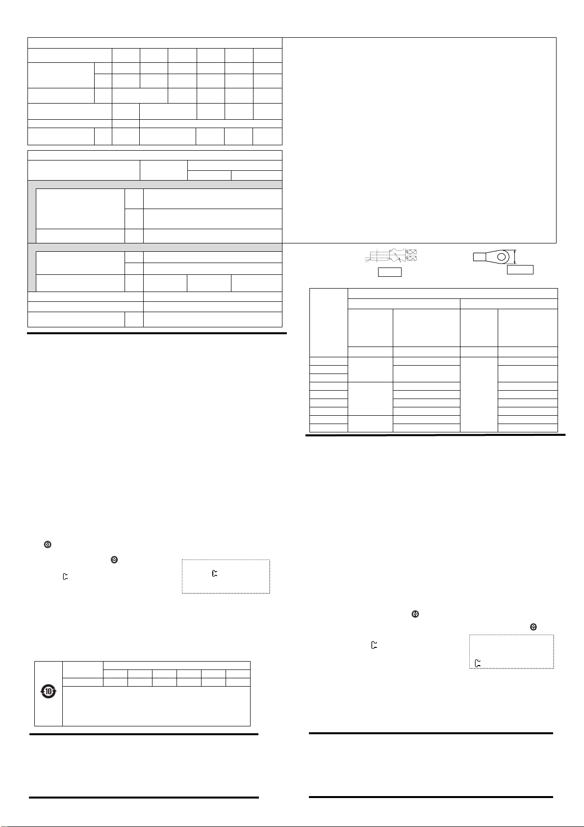
Table 2
Main terminals (压接端子连接/ Connection with crimp terminal) * 各端子分别能连接 2 个压接端子。(Fig.7)
* 不接线的端子螺钉,也应全部紧固后使用。
* 请确保相间绝缘距离。
【Note 1】 使用端子最大宽度以下的压接端子, 圆形压接端子的最大宽度请参照 Fig.7
【Note 2】 ○+2:菲利普 H 型 2 号 ○+3:菲利普 H 型 3 号
○- :
I 型螺丝刀 I-1×5.5×L 式 B ○ :套筒扳手
【Note 3】 接线后,对连接电线进行整理时,若发生折弯现象,请再次确认紧固力矩。
【Note 4】 有用于控制电路电源的 M4 螺孔。
【Note 5】 用 2 根单芯线进行接线的时候请使用相同尺寸的电线。
多股软线若无压接端子就不能使用。
使用多股软线时必须选用压接端子。
使用压接端子时电线的剥皮尺寸请按照压接端子厂家的指示。
●多股线 0.75~2.5mm2(18~14AWG) 的场合:多股线单丝根数不大于 7
●多股软线:多于上述单丝根数多股线
*When connecting two round climp terminals, set them as shown in Fig.7.
* Tighten all terminal screws, even if not use.
*Be sure to maintain insulating clearance between poles.
【Note 1】 Use round crimp terminal which width is the size specified at the maximum terminal
width or less. (Fig.8)
【Note 2】 ○+ 2:Philips PH2 φ6 ○+ 3:Philips PH3 φ8
○- :Slotted-head screw I-1×5.5×L Type B 〇 :Socket wrench
【Note 3】 After alignment or bending back of connected wires, check the tightening torque again.
【Note 4】 With M4 tap for control circuit.
【Note 5】 When connecting two solid wires, use the same size wire.
Finely stranded wire without end sleeve is not applicable. Use finely stranded wire with
end sleeve. Follow the ferrule manufacturer’s instructions to determine the stripping
length of the wire when using the ferrule.
● Stranded wire (0.75 to 2.5 [mm2]): Number of solids ≦ 7
● Flexible stranded wire: Number of solids is more than the above-mentioned value.
Type [CK3-] 105 125 150 180, 220 300, 400 600, 800
【Note 4】
多股线 /多股软线
Stranded /
Flexible stranded
[mm2] 1.5~50 1.5~120 1.5~150 2.5~240 2.5~300 50~300
AWG
kcmil 14~1/0 14~250 14~300 14~400 14~600 1/0~600
端子最大宽度【Note 1】
Max. Width [mm] 22.3 28.9 36.5 44.5 51
端子螺钉尺寸
Terminal screw size M6 M8 M10 M12 M16
紧固工具 / Tool 【Note 2】 ○
,
○+ 3 ○
紧固力矩 【Note 3】
Tightening torque [N・m] 4~5 9~11 15~20 35~45 75~100
Control terminals & Auxiliary terminals
Type [CK3-] 105, 125, 150
180, 220, 300, 400
600, 800
Coil Aux.
直接连接 / Direct connection
单芯线 / 多股线/ 【Note 5】
多股软线(有压接端子)
Solid / Stranded /
Flexible stranded with end sleeve
[mm2]
1×(0.75~2.5)
2×(0.75~1.5)
2×(1.5~2.5)
AWG 1×(18~14)
2×(18~16)
2×(16~14)
电线剥皮尺寸
Stripped length [mm] 10
压接端子连接/ Connection with crimp terminal
多股线 /多股软线
Stranded, Flexible stranded
[mm2] 0.75~2.5
AWG 18~14
端子最大宽度/ Max. Width
【Note 1】 [mm] 7.7 7.9 7.7
端子螺钉尺寸/ Terminal screw size M3.5
紧固工具 / Tool 【Note 2】 ○+2 ○-1
紧固力矩 【Note 3】
Tightening torque [N・m] 0.8~1
C
HAN
GS
HU
S
WIT
C
H
G
EAR MF
G
.
CO
., LTD
(FORMER CHANGSHU SWITCHGEAR PLANT)
No.8 Jianye Road, Changshu Jiangsu P.R. China
Phone : 0512-52842237 52846851
URL http://www.riyue.com.cn
常熟开关制造有限公司(原常熟开关厂)
地址:中国江苏省常熟市建业路8号
电话:0512-52842237 52846851
URL http://www.riyue.com.cn
端子板
Terminal
plate
Fig.7 压接端子
Round climp
terminals
最大宽度
Max width
Fig.8
Table 3
Type
GB14048.4, IEC60947-4-1
Type“1” Type“2”
短路电流
Prospective
Current
“Iq”
CM1
断路器额定电流
Breaker Max Rating
短路电流
Prospective
Current
“Iq”
RT16
熔断器额定电流
Fuse Max Rating
[kA] [A] [kA] [A]
CK3-105
18
160
50
160
CK3-125 225 250
CK3-150
CK3-180
35
225 315
CK3-220 315 315
CK3-300 400 400
CK3-400 500 500
CK3-600 50 800 630
CK3-800 800 800
This manual suits for next models
12
Other Riyue Relay manuals


Popular Relay manuals by other brands


Watts
Watts ProMelt Contactor Pro CP-50 Instructions for installing

ADTRAN
ADTRAN T1-FT1 CSU Specification sheet

Westinghouse
Westinghouse HZ instructions

Schweitzer Engineering Laboratories
Schweitzer Engineering Laboratories SEL-251D-1 instruction manual

GE
GE UR series Release notes

Omron
Omron K8AB-AS product manual