manuals.online logo
Brands
  1. Home
  2. •
  3. Brands
  4. •
  5. gefran
  6. •
  7. Relay
  8. •
  9. gefran GTS-T 10/230 User manual

gefran GTS-T 10/230 User manual

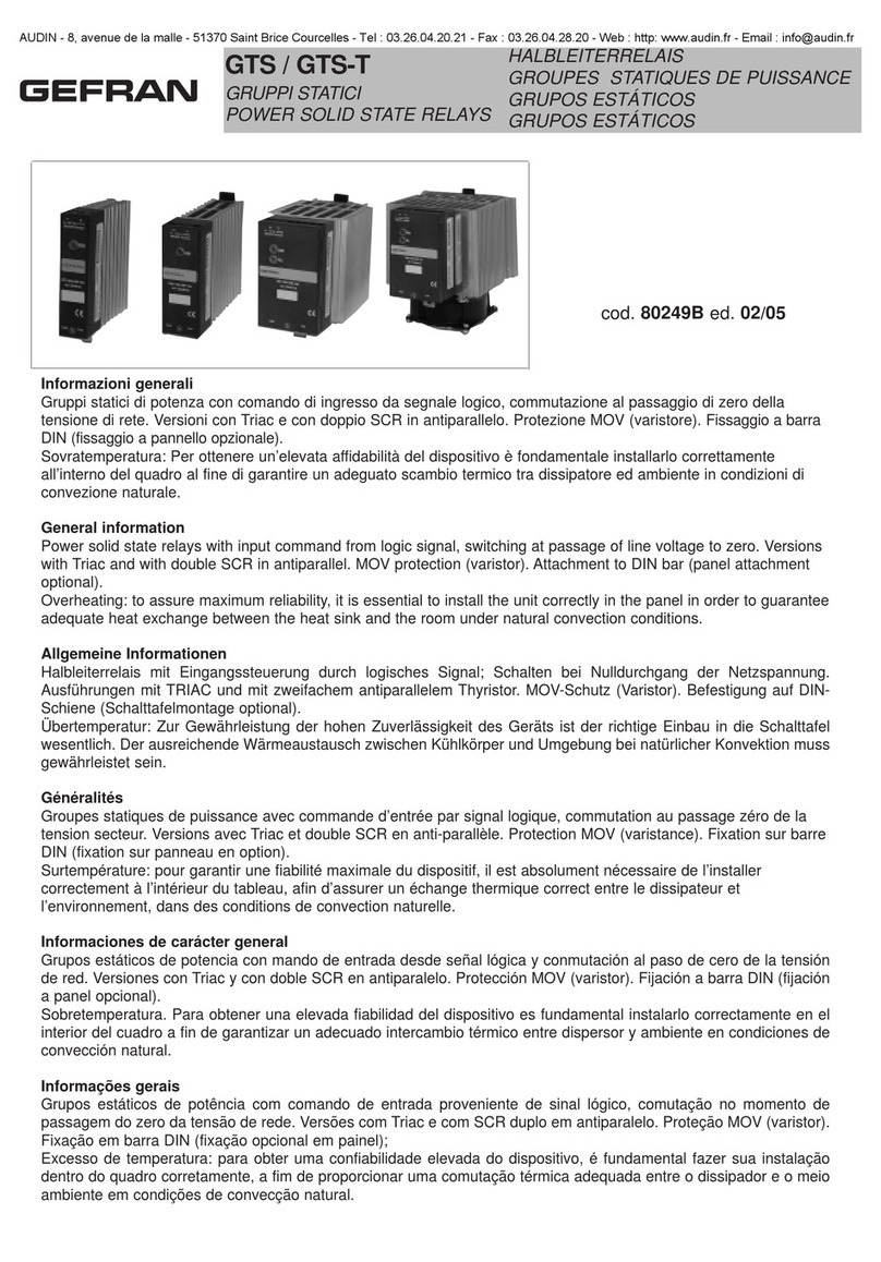
cod. 80249B ed. 02/05
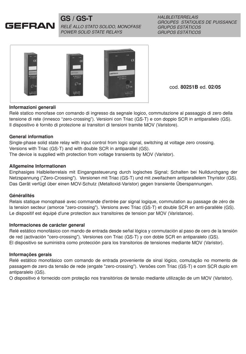
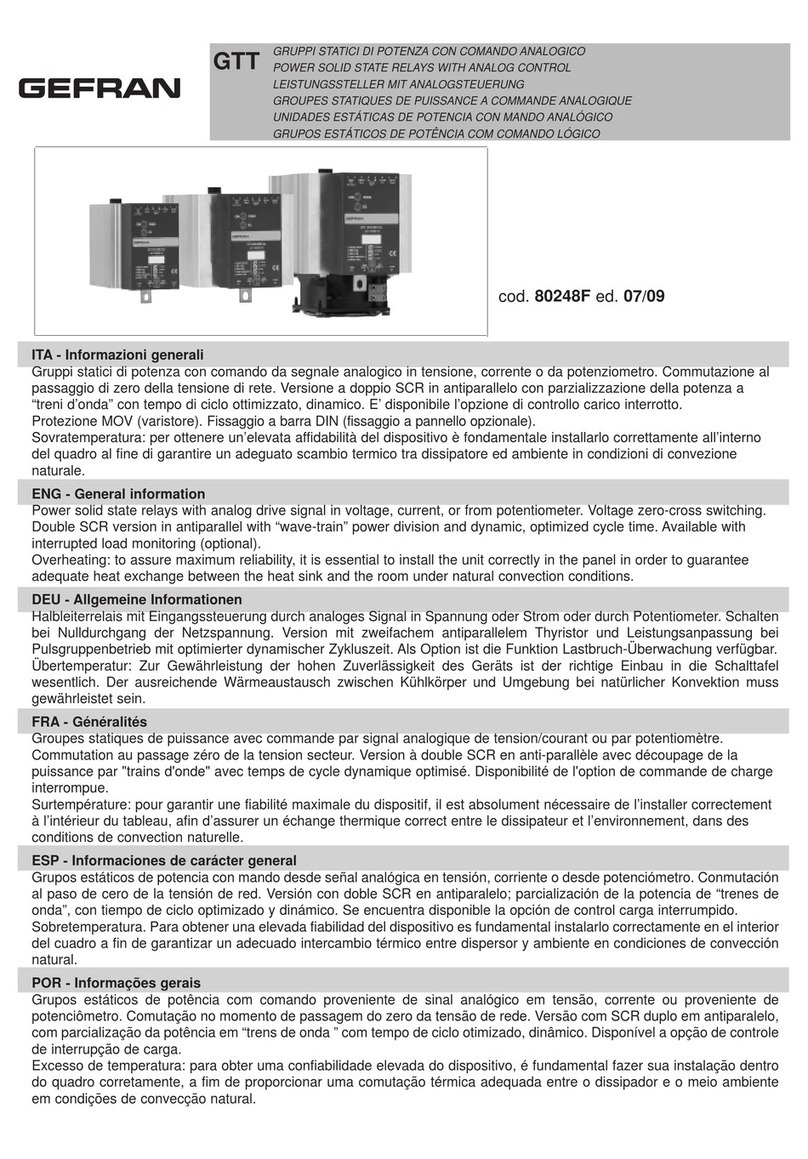
Informazioni generali
Gruppi statici di potenza con comando di ingresso da segnale logico, commutazione al passaggio di zero della
tensione di rete. Versioni con Triac e con doppio SCR in antiparallelo. Protezione MOV (varistore). Fissaggio a barra
DIN (fissaggio a pannello opzionale).
Sovratemperatura: Per ottenere un’elevata affidabilità del dispositivo è fondamentale installarlo correttamente
all’interno del quadro al fine di garantire un adeguato scambio termico tra dissipatore ed ambiente in condizioni di
convezione naturale.
General information
Power solid state relays with input command from logic signal, switching at passage of line voltage to zero. Versions
with Triac and with double SCR in antiparallel. MOV protection (varistor). Attachment to DIN bar (panel attachment
optional).
Overheating: to assure maximum reliability, it is essential to install the unit correctly in the panel in order to guarantee
adequate heat exchange between the heat sink and the room under natural convection conditions.
Allgemeine Informationen
Halbleiterrelais mit Eingangssteuerung durch logisches Signal; Schalten bei Nulldurchgang der Netzspannung.
Ausführungen mit TRIAC und mit zweifachem antiparallelem Thyristor. MOV-Schutz (Varistor). Befestigung auf DIN-
Schiene (Schalttafelmontage optional).
Übertemperatur: Zur Gewährleistung der hohen Zuverlässigkeit des Geräts ist der richtige Einbau in die Schalttafel
wesentlich. Der ausreichende Wärmeaustausch zwischen Kühlkörper und Umgebung bei natürlicher Konvektion muss
gewährleistet sein.
Généralités
Groupes statiques de puissance avec commande d’entrée par signal logique, commutation au passage zéro de la
tension secteur. Versions avec Triac et double SCR en anti-parallèle. Protection MOV (varistance). Fixation sur barre
DIN (fixation sur panneau en option).
Surtempérature: pour garantir une fiabilité maximale du dispositif, il est absolument nécessaire de l’installer
correctement à l’intérieur du tableau, afin d’assurer un échange thermique correct entre le dissipateur et
l’environnement, dans des conditions de convection naturelle.
Informaciones de carácter general
Grupos estáticos de potencia con mando de entrada desde señal lógica y conmutación al paso de cero de la tensión
de red. Versiones con Triac y con doble SCR en antiparalelo. Protección MOV (varistor). Fijación a barra DIN (fijación
a panel opcional).
Sobretemperatura. Para obtener una elevada fiabilidad del dispositivo es fundamental instalarlo correctamente en el
interior del cuadro a fin de garantizar un adecuado intercambio térmico entre dispersor y ambiente en condiciones de
convección natural.
Informações gerais
Grupos estáticos de potência com comando de entrada proveniente de sinal lógico, comutação no momento de
passagem do zero da tensão de rede. Versões com Triac e com SCR duplo em antiparalelo. Proteção MOV (varistor).
Fixação em barra DIN (fixação opcional em painel);
Excesso de temperatura: para obter uma confiabilidade elevada do dispositivo, é fundamental fazer sua instalação
dentro do quadro corretamente, a fim de proporcionar uma comutação térmica adequada entre o dissipador e o meio
ambiente em condições de convecção natural.
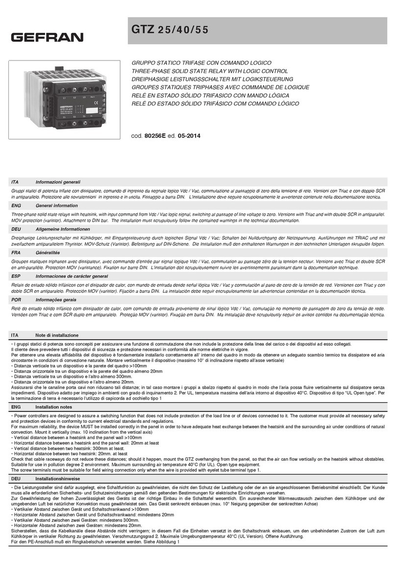
GTS / GTS-T
GRUPPI STATICI
POWER SOLID STATE RELAYS
HALBLEITERRELAIS
GROUPES STATIQUES DE PUISSANCE
GRUPOS ESTÁTICOS
GRUPOS ESTÁTICOS
Note di montaggio:
I gruppi statici di potenza sono concepiti per assicurare una funzione di commutazione che non include la
protezione della linea del carico o dei dispositivi ad esso collegati. Il cliente deve prevedere tutti i dispositivi di
sicurezza e protezione necessari in conformità alle norme elettriche in vigore. Per ottenere un’elevata
affidabilità del dispositivo è fondamentale installarlo correttamente all’interno del quadro al fine di garantire un
adeguato scambio termico tra dissipatore ed ambiente in condizioni di convezione naturale
Massima temperatura dell’ambiente 40°C “Open Type Equipment” utilizzabile con grado di inquinamento 2 o
migliore.
Montare verticalmente il dispositivo (max 10° di inclinazione rispetto l’asse verticale).
- Distanza verticale tra un dispositivo e la parete del quadro >100mm.
- Distanza orizzontale tra un dispositivo e la parete del quadro almeno 20mm.
- Distanza verticale tra un dispositivo e l’altro almento 300mm.
- Distanza orizzontale tra un dispositivo e l’altro almeno 20mm.
Assicurarsi che le canaline porta cavi non riducano tali distanze; in tal caso montare i gruppi a sbalzo rispetto
al quadro in modo che l’aria possa fluire verticalmente sul dissipatore senza impedimenti.
Installation notes:
Power controllers are designed to assure a switching function that does not include protection of the load line
or of devices connected to it. The customer must provide all necessary safety and protection devices in confor-
mity to current electrical standards and regulations. To assure maximum reliability, it is essential to install the
unit correctly in the panel in order to guarantee adequate heat exchange between the heat sink and the room
under natural convection conditions.
Maximum surrounding air temperature 40°C “Open Type Equipment” suitable for use in pollution degree 2 or
better.
Install the unit vertically (max 10° inclination from vertical axis).
- Vertical distance between unit and panel wall >100 mm
- Horizontal distance between unit and panel wall at least 20 mm
- Vertical distance between one unit and the next at least 300 mm
- Horizontal distance between one unit and the next at least 20 mm
Make sure that the wire raceways do not reduce such distances. If they do, install the units cantilevered to the
panel so that air can flow vertically onto the heat sink without obstruction.
Hinweise zur Montage:
Die Leistungssteller sind dafür ausgelegt, eine Schaltfunktion zu gewährleisten, die nicht den Schutz der Lastleitung
oder der an sie angeschlossenen Betriebsmittel einschließt. Der Kunde muss alle erforderlichen Sicherheits- und
Schutzeinrichtungen gemäß den geltenden Bestimmungen für elektrische Einrichtungen vorsehen.
Zur Gewährleistung der hohen Zuverlässigkeit des Geräts ist der richtige Einbau in die Schalttafel wesentlich.
Der ausreichende Wärmeaustausch zwischen Kühlkörper und Umgebung bei natürlicher Konvektion muss
gewährleistet sein.
Maximale Umgebungstemperatur 40°C “Open Type Equipment”; verwendbar bei Verschmutzungsgrad 2 oder
besser.
Das Gerät senkrecht einbauen (max. 10° Neigung gegenüber der senkrechten Achse).
- Vertikaler Abstand zwischen Gerät und Schaltschrankwand >100 mm.
- Horizontaler Abstand zwischen Gerät und Schaltschrankwand: mindestens 20 mm.
- Vertikaler Abstand zwischen zwei Geräten: mindestens 300 mm.
- Horizontaler Abstand zwischen zwei Geräten: mindestens 20 mm.
Sicherstellen, dass die Kabelkanäle diese Abstände nicht verringern; in diesem Fall die Einheiten versetzt in den
Schaltschrank einbauen, um den unbehinderten Zustrom der Luft zum Kühlkörper in vertikaler Richtung zu
gewährleisten.
Prescriptions de montage:
Les gradateurs de puissance sont conçus pour assurer une fonction commutation qui n'inclut pas la protection
de la ligne de charge ou des dispositifs raccordés à celle-ci. Le client devra prévoir tous les dispositifs de sécu-
rité et de protection nécessaires, conformément aux normes électriques en vigueur. Pour garantir une fiabilité
maximale du dispositif, il est absolument nécessaire de l’installer correctement à l’intérieur du tableau, afin
d’assurer un échange thermique correct entre le dissipateur et l’environnement, dans des conditions de con-
vection naturelle.
Température ambiante maximum 40°C “Open Type Equipment” utilisable avec un degré de pollution 2 ou
meilleur.
Monter le dispositif en position verticale (inclinaison maximale de 10° par rapport à l’axe vertical).
- Distance verticale entre un dispositif et la paroi du tableau >100 mm
- Distance horizontale entre un dispositif et la paroi du tableau d’au moins 20 mm
- Distance verticale entre deux dispositifs d’au moins 300 mm
- Distance horizontale entre deux dispositifs d’au moins 20 mm
S’assurer que les goulottes des câbles ne réduisent pas ces distances; le cas échéant, installer les groupes en
porte-à-faux par rapport au tableau, de manière à ce que l’air puisse circuler verticalement sur le dissipateur
sans rencontrer d’obstacles.
Notas de montaje:
Los grupos estáticos de potencia están previstos para garantizar una función de conmutación que no incluye la
protección de la línea de carga ni de los dispositivos a él conectados. El cliente debe instalar todos los disposi-
tivos de seguridad y protección necesarios, en conformidad con lo establecido por las normas vigentes
sobre equipos eléctricos. Para obtener una elevada fiabilidad del dispositivo es fundamental instalarlo correcta-
mente en el interior del cuadro a fin de garantizar un adecuado intercambio térmico entre dispersor y ambiente
en condiciones de convección natural.
Máxima temperatura del ambiente 40 °C “Open Type Equipment” utilizable con grado de contaminación 2 o
mejor.
Montar verticalmente el dispositivo (máx. 10° de inclinación respecto del eje vertical).
- Distancia vertical entre un dispositivo y la pared del cuadro >100 mm.
- Distancia horizontal entre un dispositivo y la pared del cuadro al menos 20 mm.
- Distancia vertical entre uno y otro dispositivo al menos 300 mm.
- Distancia horizontal entre uno y otro dispositivo al menos 20 mm.
Controlar que los canales portacables no reduzcan las distancias indicadas; en tal caso montar los grupos
alternados respecto del cuadro, de manera que el aire pueda fluir verticalmente sobre el dispersor sin obstáculos.
Notas de montagem:
Os grupos estáticos de potência foram concebidos para garantir uma função de comutação que não inclui pro-
teção da linha de carga ou dos dispositivos ligados à carga. O cliente tem de providenciar por si a montagem
de todos os dispositivos de segurança e proteção necessários, de acordo com as normas elétricas em vigor.
Para obter uma confiabilidade elevada do dispositivo, é fundamental fazer sua instalação dentro do quadro
corretamente, a fim de proporcionar uma comutação térmica adequada entre o dissipador e o meio ambiente em
condições de convecção natural.
Temperatura ambiente máxima 40°C “Open Type Equipment” utilizável com grau de poluição 2 ou melhor.
Monte o dispositivo verticalmente (com um máx. de 10° de inclinação em relação ao eixo vertical).
- A distância vertical entre qualquer dispositivo e a parede do quadro tem de ser >100 mm
- A distância horizontal entre qualquer dispositivo e a parede do quadro tem de ser, pelo menos, de 20 mm
- A distância vertical entre dois dispositivos consecutivos tem de ser, pelo menos, de 300 mm.
- A distância horizontal entre dois dispositivos consecutivos tem de ser, pelo menos, de 20 mm.
Assegure-se de que os conduites dos cabos não reduzam estas distâncias; em tal caso, monte os grupos em
escada em relação ao quadro, de modo que o ar possa circular verticalmente no dissipador, sem encontrar
obstáculos.
I gruppi statici devono essere protetti al corto circuito da fusibili del tipo indicato:
Equipment should be short circuit protected by semiconductor fuse type:
Die Leistungssteller müssen mit Sicherungen des angegebenen Typs gegen Kurzschluss geschützt werden:
Les groupes statiques doivent être protégés contre le court-circuit à l'aide de fusibles du type indiqué :
Los grupos estáticos deben ser protegidos contra cortocircuitos mediante fusibles del tipo que se indica:
Os grupos estáticos devem estar protegidos contra curto-circuito por fusíveis do tipo indicado:
Model Fuse manufacturer Fuse Model size
GTS-T 10/230 Bussmann Div Cooper (UK) Ltd FWC10A10F 10x38
GTS 15/230, GTS 15/480 Bussmann Div Cooper (UK) Ltd FWC16A10F 10x38
GTS 25/480, GTS-T 20/230 Bussmann Div Cooper (UK) Ltd FWC25A10F 10x38
GTS-T 25/230
GTS 40/230, GTS 40/480 Bussmann Div Cooper (UK) Ltd FWP40A14F 14x51
GTS 50/230, GTS 50/480 Bussmann Div Cooper (UK) Ltd FWP63A22F 22x58
GTS 60/230, GTS 60/480 Bussmann Div Cooper (UK) Ltd FWP80A22F 22x58
GTS 75/230, GTS 75/480
GTS 90/230, GTS 90/480 Bussmann Div Cooper (UK) Ltd FWP100A22F 22x58
GTS 120/230, GTS 120/480 Bussmann International Inc. USA 170M1418 000-TN/80
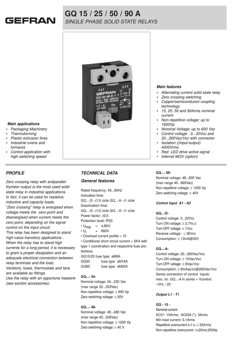
TABELLA 1 CARATTERISTICHE MORSETTI E CONDUTTORI
TABLE 1 OF TERMINALS AND CONDUCTORS
TABELLE 1: EIGENSCHAFTEN DER KLEMMEN UND LEITER
TABLEAU 1 DES CARACTERISTIQUES DES BORNES ET DES
CONDUCTEURS
TABLA 1 DE CARACTERÍSTICAS BORNES Y CONDUCTORES
TABELA 1 DE CARACTERÍSTICAS DE BORNES E CONDUTORES
6mm2/ 10AWG 0,6Nm max
6mm2/ 10AWG 0,4 - 0,6Nm
6mm2/ 10AWG 1,3 - 1,8Nm
6mm2/ 10AWG 0,6Nm max
6mm2/ 10AWG 0,4 - 0,6Nm
6mm2/ 10AWG 1,3 - 1,8Nm
2,5mm2/ 12AWG 0,6Nm max
16mm2/ 6AWG 1,5 - 2,2Nm
2,5mm2/ 12AWG 0,6Nm max
50mm2/ 1AWG 3,5 - 6Nm
50mm2/ 1AWG 1,8 - 2,5Nmm
2,5mm2/ 12AWG 0,6Nm max
50mm2/ 1AWG 3,5 - 6Nm
50mm2/ 1AWG 1,8 - 2,5Nmm
2,5mm2/ 12AWG 0,6Nm max
50mm2/ 1AWG 3,5 - 6Nm
50mm2/ 1AWG 1,8 - 2,5Nm
(**) Le sezioni massime indicate sono riferite a cavi in rame unipolari isolati in PVC.
(**) The max. sections specified refer to unipolar copper wires isolated in PVC.
(**) Die angegebenen maximalen Querschnitte beziehen sich auf einpolige Kupferkabel mit PVC-Isolierung.
(**) Les sections maximales indiquées se rapportent à des câbles en cuivre unipolaires isolés en PVC
(**) Las secciones máximas indicadas se refieren a cables de cobre unipolares aislados de PVC.
(**) As seções máximas indicadas referem-se a cabos de cobre, unipolares, isolados, de PVC.
Taglia
Size
Baugröße
Taille
Tamaño
Tamanho
Area di contatto (LxP) tipo vite
Contact area (WxD) screw type
Kontakt-fläche (BxT) Schraubentyp
Surface decontact (LxP)type de vis
Área decontacto (AxP)tipo tornillo
Área de contato (LxP) tipo parafuso
Tipo capicorda preisolato
Type of preisolated terminal
Isolierter Kabelschuh
Type de cosse pré-isolée
Tipo terminal de cable preaislado
Tipo de etiqueta pré isolada
Sez.** max conduttore coppia di serraggio
Max section. ** conductor tightening torque
Leiter-querschnitt ** Anzugsdreh- moment
Sect. ** maxi conducteurcouple de serrage
Sec. ** máx conductor par de apriete
Seção ** máx condutor binário de aperto
10/15/20A
25A
40A
50/60A
75-90A
120A
6,4x9 M3
6,4x9 M3
9x12 M5
6,4x9 M3
6,4x9 M3
9x12 M5
6,3x9 M3
12x12 M5
11,5x12 M5
6,3x9 M3
16x18 M6
14x16 M5
6,3x9 M3
16x18 M6
14x16 M5
6,3x9 M3
16x18 M6
14x16 M5
1, 2, 4
1, 2, 4
1
1, 2, 4
1, 2
1
1, 2, 3
1, 2
1
1, 2, 3
1, 2
1
1, 2, 3
1, 2
1
1, 2, 3
1, 2
1
C
P
G
C
P
G
C
P
G
C
P
G
C
P
G
C
P
G
CMORSETTO DI COMANDO
CONTROL TERMINAL
STEUERKLEMME
BORNE DE COMMANDE
BORNE DE MANDO
BORNE DE COMANDO
PMORSETTO DI POTENZA
POWER TERMINAL
LEISTUNGSKLEMME
BORNE DE PUISSANCE
BORNE DE POTENCIA
BORNE DE POTÊNCIA
GMORSETTO DI TERRA
GROUND TERMINAL
BORNE DE TERRE
ERDUNGSKLEMME
BORNE DE TIERRA
BORNE DE TERRA
1234
24mm 127mm
108mm
100mm
GTS 60
GTS 90 (senza ventola)
GTS 90 (without fan)
GTS 90 (ohne Lüfter)
GTS 90 (sans ventilateur)
GTS 90 (sin ventilador)
GTS 90 (sem ventilador)
GTS 120 (con ventola)
GTS 120 (with fan)
GTS 120 (mit Lüfter)
GTS 120 (avec ventilateur)
GTS 120 (con ventilador)
50mm
profondità = 107mm
peso = 320g peso = 1200g
profondità =152mm
peso GTS 90 = 1300g peso GTS 120 = 1700g
14mm
profondità =145mm
peso = 540g
profondità =142mm
35mm
GTS 40
GTS 15
GTS 25
GTS-T 20
GTS-T 10
18mm
82mm
GTS 25A/480 Vac
AC1 50/60 Hz
Load Line
ON/OFF Control
6÷32Vcc
ON
+
GTS 40A/480 Vac
AC1 50/60 Hz
Load Line
6÷32Vcc
ON/OFF Control
ON
+
GTS 60A/480 Vac
AC1 50/60 Hz
Load
+
ON/OFF Control
6÷32Vcc
ON
AL
Line
GTS 60A/480 Vac
AC1 50/60 Hz
Load
+
ON/OFF Control
6÷32Vcc
ON
AL
Line
30 mm
Load Line
profondità =132mm
peso = 900g
GTS 50A/480 Vac
AC1 50/60 Hz
ON
AL
ON/OFF Control
6÷32Vcc
+
GTS 50
60 mm
depth = 107mm
tiefe = 107mm
profondeur = 107mm
profundidad = 107mm
profundidade = 107mm
depth=142mm
tiefe =142mm
profondeur =142mm
profundidad =142mm
profundidade =142mm
depth =132mm
tiefe =132mm
profondeur =132mm
profundidad =132mm
profundidade =132mm
depth =152mm
tiefe =152mm
profondeur =152mm
profundidad =152mm
profundidade =152mm
depth =145mm
tiefe =145mm
profondeur =145mm
profundidad =145mm
profundidade =145mm
weight = 320g
gewicht = 320g
poids = 320g
peso = 320g
peso = 320g
weight = 540g
gewicht = 540g
poids = 540g
peso = 540g
peso = 540g
weight = 900g
gewicht = 900g
poids = 900g
peso = 900g
peso = 900g
weight = 1200g
gewicht = 1200g
poids = 1200g
peso = 1200g
peso = 1200g
weight GTS 90 = 1300g
gewicht GTS 90 = 1300g
poids GTS 90 = 1300g
peso GTS 90 = 1300g
peso GTS 90 = 1300g
weight GTS 120 = 1700g
gewicht GTS 120 = 1700g
poids GTS 120 = 1700g
peso GTS 120 = 1700g
Fig. 1
Phase
Neutral
Ground
+-
Logic Output
Load Fuse
Controller
Load Line
+
ON/OFF Control
6÷32Vcc
GTS 60A/480 Vac
AC1 50/60 Hz
AL
ON
Fig. 3
Fig. 2
W
L
M5
GTS 15-25 GTS-T
GTS 40
GTS 50-60
GTS 90-120
L
112
112
112
112
W
0
25
44
113
Ingombri: Vedi Fig. 1
Fissaggio a pannello: Vedi Fig. 2
Connessioni: Vedi Fig. 3
- Utilizzare cavi di collegamento rame 75°C il cui diametro é riportato in tabella, provvisti di terminali (ZMVV) o (ZMVV2).
- Applicare sui morsetti una coppia di serraggio indicata in tabella 1
Dimensions: see Fig. 1
Installation on panel: see Fig. 2
Connections: see Fig. 3
- Use 75°C copper (Cu) conductor only, sec next list for wire ranges AWG provided with any (ZMVV) or R/C (ZMVV2) wire terminal
(see table 1).
- The terminal tightening torque is indicated in table 1.
Außenmaße: siehe Abb. 1
Schalttafelmontage: siehe Abb. 2
Anschlüsse: siehe Abb. 3
- Kupferkabel für 75°C verwenden, deren Durchmesser den Angaben in der Tabelle entspricht und die mit Kabelschuhen (ZMVV)
oder (ZMVV2) versehen sind.
- Das Anzugsdrehmoment für die Klemmen ist in Tabelle 1 angegeben.
Dimensions hors-tout: voir Fig. 1
Fixation sur panneau: voir Fig. 2
Connexions: voir Fig. 3
- Utiliser des câbles de connexion en cuivre 75°C (voir tableau des sections), pourvus de terminaux (ZMVV) ou (ZMVV2).
- Appliquer aux bornes les couples de serrage indiqués dans le tableau 1
Dimensiones: véase Fig. 1
Fijación a panel: véase Fig. 2
Conexiones: véase Fig. 3
- Utilizar cables de conexión cobre 75 °C cuyo diámetro se indica en la tabla, provistos de terminales (ZMVV) o (ZMVV2).
- En la tabla 1 se indica el par de apriete a aplicar en los bornes
Dimensões externas máximas: ver Fig. 1
Fixação em painel: ver Fig. 2
Ligações: ver Fig. 3
- Utilize cabos de ligação de cobre 75°C com diâmetro igual ao indicado na tabela e que sejam providos de terminais (ZMVV) ou
(ZMVV2).
- Aplique nos bornes um binário de aperto igual ao indicado na tabela 1
GEFRAN spa
via Sebina, 74 - 25050 Provaglio d’Iseo Brescia Italy
Tel. +39 030 9888.1 - Fax. +39 030 9839063
www.gefran.com
AVVERTENZE
Il dissipatore durante
il funzionamento
continuato può
raggiungere
temperature molto
elevate ed inoltre
mantiene una
temperatura elevata
anche
successivamente lo
spegnimento a causa
della sua elevata
inerzia termica.
WARNINGS
During continuous
operation, the heat
sink can reach very
high temperatures,
and keeps a high
temperature even
after the unit is turned
off due to its high
thermic inertia.
SICHERHEITSHINWEISE
Der Kühlkörper kann
während des
Dauerbetriebs sehr
hohe Temperaturen
erreichen und
außerdem aufgrund
seiner großen
Wärmeträgheit auch
nach der Abschaltung
noch sehr heiß sein.
AVERTISSEMENTS
Pendant son
fonctionnement
continu, le dissipateur
peut atteindre des
températures très
élevées, lesquelles
peuvent persister
même après la mise
hors tension du
dispositif, par effet de
son importante inertie
thermique.
ADVERTENCIAS
Durante el
funcionamiento
continuado el
dispersor puede
alcanzar temperaturas
muy elevadas y
mantener también
una temperatura
elevada una vez
apagado debido a su
elevada inercia
térmica.
ADVERTÊNCIAS
Em constante
funcionamento, o
dissipador pode
atingir temperaturas
muito elevadas e,
mesmo depois do
desligamento,
mantém temperatura
elevada devido à sua
alta inércia térmica.
Non lavorare sulla parte
di potenza senza aver
prima sezionato la
tensione di
alimentazione del
quadro.
DO NOT work on the
power section without
first cutting out electrical
power to the panel.
Nicht am Leistungsteil
arbeiten, ohne vorher die
Versorgungsspannung
des Schaltschranks
abgeschaltet zu haben.
Ne pas intervenir sur la
partie de puissance
sans avoir
préalablement coupé la
tension d’alimentation
du tableau.
No trabajar en la parte
de potencia sin
seccionar previamente
la tensión de
alimentación
del cuadro.
Não trabalhe na parte
de potência se não tiver
interrompido
previamente a tensão
de alimentação do
quadro.
Attenersi alle
indicazioni presenti sul
manuale tecnico.
Follow the
instructions in the
technical manual.
Die Anweisungen im
technischen Handbuch
beachten.
Respecter les
prescriptions du
manuel technique.
Atenerse a las
indicaciones del
manual técnico.
Siga as indicações
dadas no manual
técnico.
Il dispositivo è
conforme alle
norme generiche
CEI EN 61000-6-2 e
CEI EN 50081-2.
The unit conforms
to generic standards
CEI EN 61000-6-2
and CEI EN 50081-2.
Das Gerät entspricht
der Rahmennormen
CEI EN 61000-6-2
und CEI EN 50081-2.
Le dispositif est
conforme aux normes
générales
CEI EN 61000-6-2 et
CEI EN 50081-2.
El dispositivo cumple
por las normas
genéricas
CEI EN 61000-6-2 y
CEI EN 50081-2.
O dispositivo cumpre e
nas normas genéricas
CEI EN 61000-6-2 e
CEI EN 50081-2.

This manual suits for next models

17

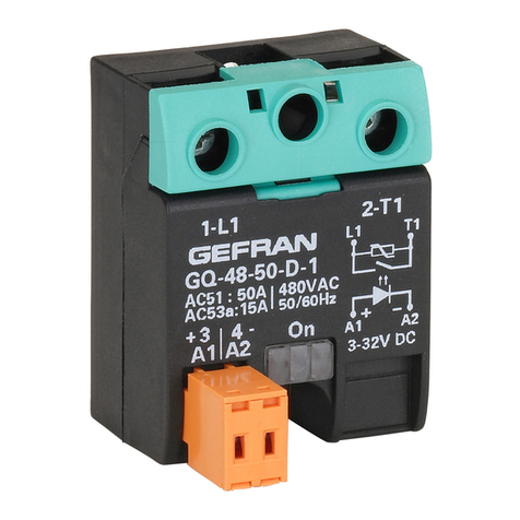
Other gefran Relay manuals

gefran GQ User manual

gefran

gefran GQ User manual

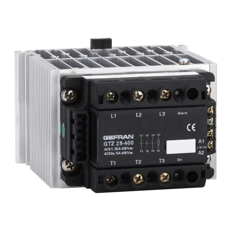
gefran GTZ-25 Series User manual

gefran

gefran GTZ-25 Series User manual

gefran GQ Series User manual

gefran

gefran GQ Series User manual

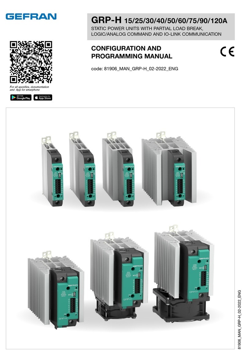
gefran GRP-H15A Owner's manual

gefran

gefran GRP-H15A Owner's manual

gefran GQ 15 Series User manual

gefran

gefran GQ 15 Series User manual

gefran GQ Series User manual

gefran

gefran GQ Series User manual

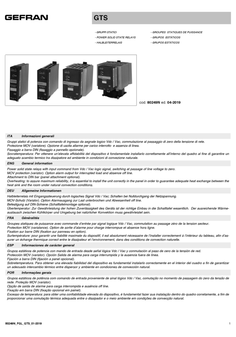
gefran GTS User manual

gefran

gefran GTS User manual

gefran GQ Series User manual

gefran

gefran GQ Series User manual

gefran GTT 25/230 User manual

gefran

gefran GTT 25/230 User manual

gefran GTZ 25 Quick start guide

gefran

gefran GTZ 25 Quick start guide

gefran GTZ 25 Series Instruction manual

gefran

gefran GTZ 25 Series Instruction manual

gefran GQ 15 A Series Instruction manual

gefran

gefran GQ 15 A Series Instruction manual

gefran GTZ 25 Configuration guide

gefran

gefran GTZ 25 Configuration guide

gefran GTS User manual

gefran

gefran GTS User manual

gefran GQ 15 A User manual

gefran

gefran GQ 15 A User manual

gefran GS User manual

gefran

gefran GS User manual

gefran GT 25 User manual

gefran

gefran GT 25 User manual

Popular Relay manuals by other brands

ABB REB650 Technical manual

ABB

ABB REB650 Technical manual

Siemens SIRIUS 3TK2822 operating instructions

Siemens

Siemens SIRIUS 3TK2822 operating instructions

Valcom V-9955 Specification sheet

Valcom

Valcom V-9955 Specification sheet

Omron G2RV -  1 datasheet

Omron

Omron G2RV - 1 datasheet

KATEK TeleAlarm NurseCall NC8 user manual

KATEK

KATEK TeleAlarm NurseCall NC8 user manual

Zander Aachen SR3C operating instructions

Zander Aachen

Zander Aachen SR3C operating instructions

Bayrol PM5-REL-4 user manual

Bayrol

Bayrol PM5-REL-4 user manual

Niko 10-830 manual

Niko

Niko 10-830 manual

Circutor CBS-4C manual

Circutor

Circutor CBS-4C manual

Neets 4 Relay box manual

Neets

Neets 4 Relay box manual

Schrack LSTD Series operating instructions

Schrack

Schrack LSTD Series operating instructions

ABB Sentry BSR10 Connection diagrams

ABB

ABB Sentry BSR10 Connection diagrams

Pilz PNOZ s2 operating manual

Pilz

Pilz PNOZ s2 operating manual

SICK ReLy OSSD4 operating instructions

SICK

SICK ReLy OSSD4 operating instructions

Rievtech PR-6DC-DA-R user manual

Rievtech

Rievtech PR-6DC-DA-R user manual

ERL T-PRO quick start guide

ERL

ERL T-PRO quick start guide

Delixi JSS48 Series user manual

Delixi

Delixi JSS48 Series user manual

ENDA EPDA1 quick start guide

ENDA

ENDA EPDA1 quick start guide

manuals.online logo
manuals.online logoBrands
  • About & Mission
  • Contact us
  • Privacy Policy
  • Terms and Conditions

Copyright 2025 Manuals.Online. All Rights Reserved.