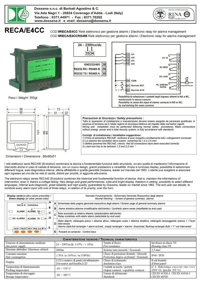
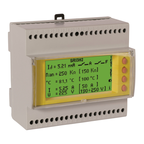
manuals.online logo
Brands
  1. Home
  2. •
  3. Brands
  4. •
  5. Dossena
  6. •
  7. Relay
  8. •
  9. Dossena DER3/0 Series User manual

Dossena DER3/0 Series User manual

Ðossena s.n.c. di BarbatiAgostino & C.
Via Ada Negri 1 -26824 Cavenago d'Adda - Lodi (ltaly)
Telefono : 0371.44971 - Fax : 0371J0202 t*#,ä,*".9
wwwdossena.it e -mail: dossena@dosSena.it
MANUALE -DI MASSIMA CORRENTE DIFFERENZIALE-OMOPOLARE DI TERRA_ SERIE : DER3/O
MANUAL - EARTH DIFFERENTIAL RELAY - SERIES : DER3/0
DER3/OD
Goo.9DER3/0D
K-35+
7t
aaaaaa
ffi
;:i¡¡È J
FH
aaatt'
T
90
I58
64
al a lr () a),:l ( )
DER3/OE
Coo.9DER3/0E
<-48+
+s+
DER3/OI
Goo. 9DER3/01
a1
a@
o
"å
OÕOO
Ge¡¡emurÀ / lvrnooucno¡t:
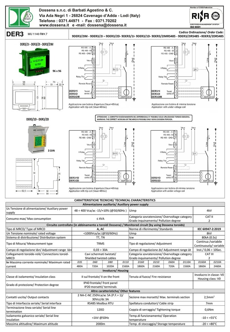
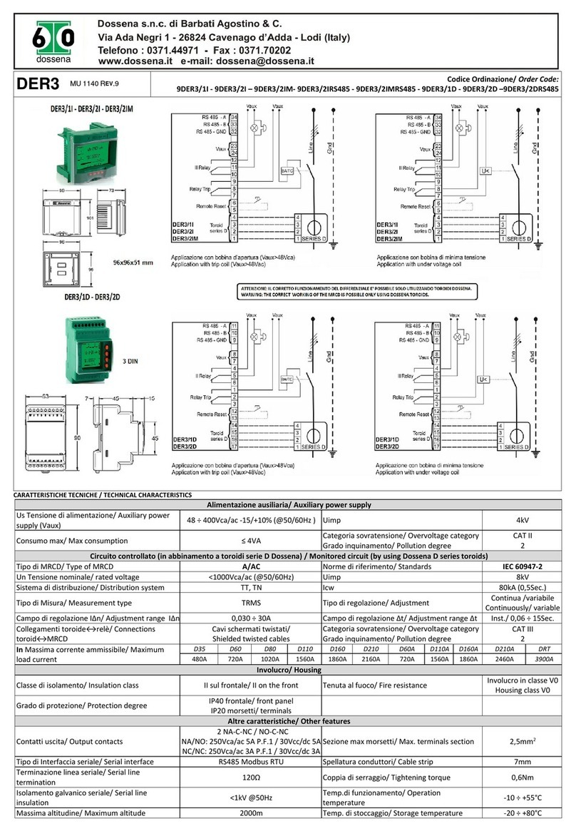
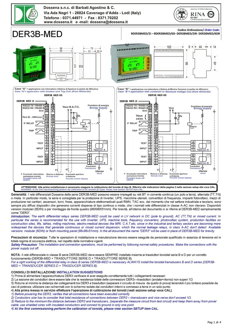
I relè differenziali della gamma DER3 Dossena possono essere impiegati su reti BT in corrente alternata di tipo TT e TN . Essi consentono di realizzare
un'adeguata selettività della protezione differenziale grazie all'ampia regolazione della soglia della corrente di dispersione (fino a 304) e della soglia di
ritardo dell'intervento (fino a Ssec). I DER3 Dossena sono perfettamente conformi alle severe normative vigenti (CEl EN 60947-2:2007 all. M ed.8 e
IEC 60947-2:2006 all. M ed.4) soddisfando cosi un duplice bisogno : la sicurezza dell'impianto e la continuità del servizio.
The earth differential relays range DER3, can be used on LV networks in alternate current, type TT and TN. They guarantee an adequate selectivity of
differential protection thanks to : wide adjustment of threshold current dispersion (until 30 A) and threshold for delay intervention (until Ssec).
DER3 Dossena are perfectly designed in accordance with strict regulations (CEl EN 60947-2 annex M ed.8 and IEC 60947-2:2006 annex M ed-4) thus
satisfying a double need: safety of facilíty and service continuity of industrial production .
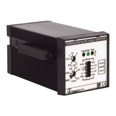
TEST Pulsante per la prova di funzionamento del relè differenziale
Test button to verifv operation of earth different¡al relav
tr Pulsante per il riarmo manuale (attivo solo in modalità reset manuale)
Manual reset button (active onlv in manual reset mode)
RST RST
0,034+304
t^ (A) Potenziometro per determinare la lÂn in abbinamento ai dip switch
Potentiometer to define lÂn in conjunction with dip switch
o.utJul'
o.s) \3
lstantaneo 'INST" / ritardato 0,06 + 5 Sec.
lnstantaneous "INST" /delay 0,06 + 5 Sec.
t (sec) Potenziometro per determinare il tempo limite di non intervento in
abbinamento ai dip switch
Potentiometer to define limit time of non intervention in coniunction
with dip switch
0.2 0.3
o.06-\+o'4
tNsrt \o.u
On On LED di segnalazione apparato alimentato ed operativo (colore verde)
LED signaling: powered and operativity of device (green color)
Fault LED multifunzione per la segnalazione di non corretto funzionamento (colore rosso)
LED Multifunction to signal incorrect working (red color)
Fault
Trip LED di segnalazione avvenuto intervento (colore rosso)
LED signaling: tripping relay (red color)
Trip?
Dip switch
N.de. * N.E.
lAx0,1 *lÅx't *
lÀx10
tx1etx10
Man. e Aut.
Stato del relè di TRIP (N.de. = normalmente diseccitato N.E. = normalmente eccitato)
/ State of TRIP relay (N.de. = normally non excíted N.E. = normally excited)
Fattori moltiplicativi per determinare la lAn in abbinamento al potenziometro lA (A)
/ Multiplier factors to define IAn in congiunctíon with potent¡ometer lL (A)
Fattori moltiplicativi per determinare il tempo di non intervento in abbinamento al
potenziometro t (sec)
/ Multiplier factors to define time of non intervention in conjunction with potentiometer t(sec)
Tipo di funzionamento del RESET / State of RESET
¡ RelaV -1
N.E.
0,1
Nl^10
tx1 0
L ResetJ
Nota: ruotando in senso antiorario il potenziometro t (sec), si inserisce la regolazione INST indipendentemente dalla posizione del dip switch
(tx1 o tx10)
Note : turning counterclockwíse the potentiometer t (sec), to insert adjustment INST índipendent of the position of dip switch
MODALITA DITARATURA DEI FATTORI Dl MOLTIPLICAZIONE: CORRENTE E TEMPO
CALIBRATION MODALITY OF MULTIPLIER FACTORS: CURREIVT AND TIME
l^=0,030+0,304 l^=0,30+34 l^=3+30A t = 0,06 + 0,5 sec. t=0,6+5sec,
l^ x 0,1 l^x10
laxl Itx1 tx10
Precauzioni di Sicurezza / Safefi precautions:
Tutte le operazioni di installazione e manutenzione devono essere eseguite da
personale qualificato in assenza di tensione ed in totale regime di sicwezza elettrica
nel rispetto delle normative vigenti.
The instattation and connection operations must be performed following normal
safety procedures. Make the connections with the power supply cut off.
SIMULÀZ. DI GUASTO . FAULTSIMUL.
DER3
L1
L2
L3
N
R=_
Caratter¡st¡che eletlñche I Electrical chancteristics
Campo di regolaz¡one ^t
Adjustment range Al lstantâneo / 0,06 + 5 Sec.
lnst/0,06+5Sec.
Tensione d¡ alimentazione
Aux power supply 48 + 400vca/ac (-15% I +100/0)
Regolazione
Ad¡uslment Cont¡nua
Constant
Frequenza Vaux
Vaux Freouencv 50/60H2 Contatti uscita
Output contacts 250Vcalac
5A DerforP.F. = 1
Consumo max
Max consumption <5VA Tipo d¡ Misura
Measurement IRI\4S
Campo d¡ regolaz¡one l^n
Adjustment range lAß 0,03 + 30A U¡mp 4kv
Icáaracfeflsfics
Tipo di rete da controllare
Type of network to control 50Hz <'lOOOVca
Sistema di distr¡buzione
Distr¡but¡on s¡stem TT. TN
Classiflcaz¡one
C/ass A, AC
Norme d¡ riferimento
Standards CEì EN 60947-2:2007 ail. N/ ed. B
IEC 60947-2:2006 annex M ed. 4
Temp. di funz¡onamento
Operation temperature -10"c + +55.C
Temp. d¡ stoccaggio
Storaqe temperature -20"C + +Bo"c
Caratteristiche meccaîiche I Mechanical chancterist¡ cs Connessioni /connections
D¡mens¡oni
Dimens¡ons 96x96x51 / 48x48x94 / 2 DIN I ls"r¡on" ma morsetti
I lTerminals section z,5mm'
Classe di isolamento
lnsulation class ll sul frontale I I Spellatura conduttor¡
I lcabte strip
ll front panel 7mm
Tenuta al fuoco
Fire-resistance lnvo¡ucro in classe V0
Housing class V0 I lCopp¡a d¡ serraggio
| ltightening torque 0,6Nm
Grado d¡ protez¡one
Degree of protection lPsO frontale i lP 20 morsetti ] lCollegament¡ trasduttore-relè
\PSO front panel / tP20 term¡nats I lConnections transducer-relav Schermati
Shielded
Modalità d¡ test / test modal¡ty
S¡mulazione di elevata lA med¡ante segnale di potenza applìcato ad
awolgimento supplementare sul trasduttore con effetto identico a
dispersione nel circu¡to primar¡o
High lA s¡mulation through power s¡gnal appl¡ed to add¡t¡onal wiríng
on the transducer w¡th same effeÇt of leakage ¡n the primary c¡rcuit.
Go¡¡slcr-r Df rNsrALLAzroNE / I ¡tstatttttou suecgsrrorvs:
1) Prima di alimentare l'apparecchiatura DER3 verificare di aver eseguito correttamente tutti i collegamenti necessari
2) La sezione dei conduttori deve essere tale che la resistenza totale delle connessioni DER3 * trasduttore (andata+ritorno) non superi lO
3) Ridurre al minimo la distanza dei collegamenti tra DER3 e trasduttore (separare il circuito di misura da quello di prova) tenendoli il più lontano
possib¡le da cavi di potenza; utilizzare cavi schermati con lo schermo isolato dai conduttori interni e connesso a terra in un solo punto.
1) Before powered the DER3, verifies that all connect¡ons have been executed correctly
2) Conductors size has to consider that total resistance connect¡ons between DER3 * transducer and vice versa don't exceed 1 A
3) Reduce to the minimum the dìstance between DER3 and transducer, separate the measure circuit from test circu¡t and keep them away from power
cables;use shielded wires w¡th insulated conductors and connect to ground in only one point.
Stcungzz¡ postlv¡ / Posmve sEcuRrry:
lmpostando il relè TRIP in modalità NE esso lavora normalmente eccitato ed i terminali N.C. e N.A. si scambiano. ln mancanza di alimentazione o
spegnimento per guasto del DER3 il relè TRIP si diseccita portandosi nella stessa posizione che avrebbe scattando per corrente oltre soglia.
Attenzione: L'impostazione della sicurezza positiva esclude la vigilanza permanente della continuità della bobina di apertura.
Setting positive secur¡ty NE (normally exc¡ted) the TRIP relay operates as normally exc¡ted NC and exchange the state in N.O.. For tacking of power
supply or power off for failure, DER3 in a trip condition as over current threshold.
Attent¡on: Setting of positive security excludes permanent detection of the continuity of open¡ng coil.
Tesr ru¡¡zlo¡t¡¡¡ex¡o / OpennnNe Tesr:
Premendo il tasto di TEST, il DER3 awia la procedura standard di TEST che, a sistema funzionante, si conclude con lo scatto del relè TRIP e la
segnalazione del relativo led, ogni differente comportamento led/relè significa che il test non è riuscito.
Attenzione: si ricorda che se il "t¡po d¡ funzionamento del reset" è impostato in "AUTO" il DER3, si resetterà automaticamente dopo qualche secondo.
Pushing the test bufton, DER3 starfs the standard procedure of test, which, if the device ís functioning the procedure ends with trip of relay and in case
of positive result the LED TRIP is lighting red. Any other conditions led/relay means test fa¡led. Attention: remind that if sefting "state of resef" ls
'AUTO" DERS resets automatically in few minutes.
Tssr rurom¡trcl (vrcrlruza corurrnun) / Auromnnc Tesr (eranetteNr sueeavtstor,t) :
1)Testdi verifica del circuito della bobina di apertura (8.4.). E'stato introdotto un sistema di controllo sulla continuità della bobina di apertura, sui suoi
collegamenii e sulla presenza dell'alimentazione.
2)Vigilanza continua su interruzioni e cortocircuiti degli awolgimenti del trasduttore toroidale e delle connessioni tra questo e ¡l DER3.
1) Control test of opening coil circuit. lt was introduced a control system of continuity of opening coil, its electric connections and power presence of opening coil.
2) Permanent control on interruptions and short circuits of transducer, windings and relative connect¡ons to DER3..
TEST
INPUT
"4" = applicazione con inle¡ruttorc ê Bo¡)ina d¡ Apêttura (a part¡rê da 48Vc¿)
"A" = appticatíon wlth breaker and Trip Co¡t (from 48vac)
Forn¡toae di enêrg¡â
Vaux B.A./tC,
48 + 400V
EøC +
I
Users
Ève¡tuale ãpeiura a dislanza Utenza
!t
0t
DER3/ OD OE
Câse
a.A.t
T.C.
Rlarmo a dl6tanza
TEST
INPUT
= appl¡cazlone con telerultore o Bob¡na di M¡n¡ßa Tensionê (a parírê da 4BVcâ)
48 + 400V 48 + ¡100V 48 + 400V
w4 +
Boblna/
co¡l
= appl¡caalon wtth contactor or M¡nímum
Case "B" Coil (îrcm 48vac)
DER3 / OD OE OI F.t _
Forn¡tore di ê¡ergÌa
Énergy súppliet
R¡ârmô a dlstânzâ Evenluale apeñura a dlBbnza Ulenza
Possib!ê remote trlppíng Usêrs
Slato dei Led tg Lecl Stato del Relè , State ofrelay Tipo di evento/guaslo I lndication offailure searchìng
ON FAULT TRIP TRIP
ON OFF ON Cambia statolchange of state La corrente r¡levata lA supera la l^n ¡mpostata
Current detected lA exceeds lÂn setted
ON LAMPEGGIA
FLASHING OFF Eccessiva temperatura interna
Excessiye internal tem perature
LAMPEGGIA
FLASHING OFF OFF Alimentazione errata (Vcc * Vca) ( ll DER3 non è operativo)
Wronq supplv (DER3 not operative)
ON ON ON Cambia stato/change of state Mancata continuità dei collegamenti al trasduttore e dei suoi
avvolgimenti; cortocircuiti negli awolgimenti di misura e/o prova
No continuity of connect¡ons to transducer and its windings; short
c¡rcuit of test and measurement windings.
ON LAIVPEGGIA
FLASHING OFF
Mancanza tensione BA, mancata continuità della BA e/o dei relativi
collegamenti
Tr¡pp¡ng Opening Coil voltage presence. No continuity of opening
co¡l and its electr¡c connect¡ons. MU 02 05t10t12
Ðossena s.n.c. di BarbatiAgostino & C.
Via Ada Negri 1 -26824 Cavenago d'Adda . Lodi (ttaty)
Telefono : A371.4Ø;971 - Fax :0371.10202 SJNA @
Ceriified Qudty SFtem
www.dossena,it e -mail: dossena@dosse¡¿.¡1
MANUALE - TRASDUTTORI DI CORRENTE TOROIDALI APRIBILI O CHIUSI - SERIE "D"
MANUAL - cLosED oR OPENED ToRotDAL cuRRENr rRArusDUcERs - sERrEs 'D.
Generalità'l trasduttori di corrente toroidali serie D, realizzati in abbinamento ai relè differenziali DER, permettono di rilevare correnti
omopolari/differenziali disperse verso terra. I trasduttori devono essere installati a monte della linea o dei carichi da proteggere e
sorvegliare. All'interno devono passare tutti i conduttori attivi (fase e neutro) delle linee monofase o trifase.
Oltre al normale awolgimento di misura della corrente disperàa, essi sono provvisti anche di un awolgimento di prova.
L'ampia gamma offre soluzioni molto varie. Sono disponibili'tàsduttor¡ in esecuzione chiusa o apribile, completano la gamma i
trasduttori di tipo sommatore e moltiplicatore di portata.
General ' The toroidal current transducer seræs D, used in conjunction with the ea¡fh differentiat retays DER, ailow to detect
homopolar/differential currents. Transducers have .to be instatled upstream of the line or load to be protected and monitored. Att
conductors (phase and neutral) of single-phase or three phase must óe passed inside the transducer.
ln addition to normal winding current of measure dispersed, they are aléo equipped with a winding test.
The wide range offers very different solutions. Transducers are ávaitabte in òtosèd or opened execution, complete the range the adder
and multiplier transducers .
Garatteristiche genera li / G e n e ra I c h a ra cterisfics
Rete da controllare
Network to control TT,TN Rapporto d¡ trasformazione
Transformation ratío 500
Temperatura di funzionamento
Operating temperature -10'C + +50"C Norme di riferimento CEI EN 009¿z-2:z0ozãÌi. rr¡leãlB-
IEC 60947-2:2006 annex M. ed. 4
di protezione
Degree of protection lP 30 collegamenti lP20
IP 30 connections lP20 Tenuta corrente cortocircuito
Keeping shorf circuit current 100k4 per 0,5 sec
100kA for 0,5 sec
Temperature di stoccaggio
Sforage temperature -20'C + +80"C lnvolucro auto-estinguente
Pl a stic self-exting uish ing housing Classe
class V0
Garatteristiche elettriche / Etectricat characteristics
DENOMINAZIONE / DENOMINATION D35 D60 D80 D1r0 Dl60 D210 D60A D11OA DI60A D2lOA
Codice ordinazione
Code 9D35 9D60 9D80 9D110 9D160 9D210 9D6OA 9D110A 9D160A 9D2'10A
Diametro interno utile (mm) 35 60 80 110 160 210 60 110 160 210
Valore min (A) 0,03 0,03 0,03 0,3 0,3 0,3 0,3 0,3 0,3 1
n (A)
Corrente ln 80 120 170 260 310 360 120 260 310 410
(A)
Max corrente
Max 480 720 1020 1 560 1860 2160 720 I 560 1 860 2460
Applicazione
Application Ulilizzare solo con relè differenziale serie DER
Use only with ea¡fh differential relay serþs DER
Gonsigli di installazione / lnstattation suggesúions
t
I -.'-
Sgancio
- Le connessioni al trasduttore di corrente toroidale richiedono faston femmine standard da 6,3mm.
- L'aggancio awiene con facilità, per lo sgancio agire, come nella foto, facendo leva con un cãcciavite
- I cavi all'interno del trasduttore, devono essere uniti e centrati rispettá al foro
- Non curvare cavi / barre nelle vicinanze dei trasduttori
- ll diametro interno del trasduttore deve essere circa il doppio del diametro dell'insieme dei cavi
passanti.
- The toroidal current transducer connections require 6.3mm female standard faston.
- Push to fix the transducer on DtN rail, to remove it, use a screw-driver, as shown in the picture.
- cables inside the transducer has fo be centred and combined together.
- Do not bend cables/bars near transducer
- consider that the internal diameter of transducer has approx. double respect the
total combination of passing cables
Xc
B
E
c
E
G
D210 D60A D11OA
D35 D60 D80 D110 D160 Dl60A D21OA
Tipo di nucleo / Core type chiuso / closed aperto / open
35 60 110 160 210 60 110 160 210
A (mm) BO
280,5 121 178,5
B (mm) 99,5 124,5 144,5 180,5 230,5 228,5 278
200,5 250,5 130 198
C (mm) 70 94,5 114,5 150,5 248 298
85 1'10 135 54,5 B4 109 134
D (mm) 44,5 57 67
16 21 21 21
E (mm)
94,5 150,5
F (mm) 200,5 250,5
31 31 26 31
G (mm) 26 ¿o 26 31 31 31
155 197 227 117 155 197 227
H (mm) 104 117 125
92 '103 111 141 183 213 103 141 183 213
l(mm)
dossena
Dimensioni / Dimensions
Schemi di inserzione / Wiring diagrams
Forn¡tore di eneroia
Energy Supply- conduttore d¡ lem
Crcund cable L1t2L3N cable f|"LN nvestimento isolante eslerno del cavo
J- Extemal cable
Conduttore di lerra I
Eêütrs e944!9þ!/
NOTA NOTA
Quando ¡l cavo è prowisto di amatura metallica e quest'uliima
attråversa il trasduttore d¡ corrente toro¡dale, il collegamenlo di messa
a tera deve essere come sopñ
NOTE
When the cable has a metallic sh¡eldíng, ctosslng the ¡oroídal eurrcnt
tansducet, the eadh connection nust be as upper,
L'evenluale conduttore di terrã, dovrà passare all'esterno
Trasduftore
Trcnsduêer l-
Utenza
Users NOTE
lf present, the ground cable, must be kept outs¡de the
toro¡dal cuïent ttansdu cet
Er
DER
Esempi applicativi / Application examples
Conirollo sul collegamento a terra del neutro
Control the connection of neutral to ground
Schema generale di inserzione
General connection drawi ng Trasformatori in parallelo
Parallel transformers
À^^Trasf. MT/BT
MV\LV Transf.
DER
DER
Bobina d¡ Apertura
Trasduttore
Trip CoiI
Utenza
¿tsers
Trasf. MTIBT
MU/LV Transf.
l
)
DER
Trasf. MT/BT
MU/LV Transf.
Bobina di Apertura
Trip Coil---ì
Utenza
users
Al dispositivo di
to sgancio/
device
I
I
I
'-
Trasf. MT/BT
MV|LVT/ansf.
Bobina di
lrip Coìl
Le d¡mension¡ e le caratteristiche tecn¡che non sono impegnative e sono mod¡f¡cabili senza preavvisi da parte dell'azienda costruttrice
Dimensions and technical characteristics are not b¡nd¡ng and they can be modif¡ed without notice from the manufacturer.
Rev.01 MU 1135 0511012012

This manual suits for next models

6

Other Dossena Relay manuals

Dossena 9DER3/2IM User manual

Dossena

Dossena 9DER3/2IM User manual

Dossena DER3B-MED Series User manual

Dossena

Dossena DER3B-MED Series User manual

Dossena RECA/E8 User manual

Dossena

Dossena RECA/E8 User manual

Dossena 9DER3/1DLCC User manual

Dossena

Dossena 9DER3/1DLCC User manual

Dossena SRI3/I2 User manual

Dossena

Dossena SRI3/I2 User manual

Dossena DER3BDUAL User manual

Dossena

Dossena DER3BDUAL User manual

Dossena RECA/E4CC User manual

Dossena

Dossena RECA/E4CC User manual

Dossena SRI3/D2 User manual

Dossena

Dossena SRI3/D2 User manual

Dossena SRI3/H2 User manual

Dossena

Dossena SRI3/H2 User manual

Dossena DER3B-DUAL Series User manual

Dossena

Dossena DER3B-DUAL Series User manual

Dossena DER3/0 Series User manual

Dossena

Dossena DER3/0 Series User manual

Dossena DER3 User manual

Dossena

Dossena DER3 User manual

Dossena DER3 User manual

Dossena

Dossena DER3 User manual

Dossena DER3/1DL User manual

Dossena

Dossena DER3/1DL User manual

Dossena RECA/E4 User manual

Dossena

Dossena RECA/E4 User manual

Dossena RECA/E8CC User manual

Dossena

Dossena RECA/E8CC User manual

Popular Relay manuals by other brands

GE RPM 13A instructions

GE

GE RPM 13A instructions

GE D30 series instruction manual

GE

GE D30 series instruction manual

Pilz PNOZ XV3 operating instructions

Pilz

Pilz PNOZ XV3 operating instructions

Siemens SIPROTEC 7SA511 instruction manual

Siemens

Siemens SIPROTEC 7SA511 instruction manual

Alstom P50 Agile user guide

Alstom

Alstom P50 Agile user guide

Reer MOSAIC MR8 Quick installation guide

Reer

Reer MOSAIC MR8 Quick installation guide

Jung RS8REGHE operating instructions

Jung

Jung RS8REGHE operating instructions

Rockwell Automation Allen-Bradley E3 quick start guide

Rockwell Automation

Rockwell Automation Allen-Bradley E3 quick start guide

Allen-Bradley PowerFlex 3P-FCOVPD-B-FA installation instructions

Allen-Bradley

Allen-Bradley PowerFlex 3P-FCOVPD-B-FA installation instructions

E-Mon D-Mon Class 3000 Description & Operating manual

E-Mon

E-Mon D-Mon Class 3000 Description & Operating manual

Rockwell Automation Allen-Bradley 700-SA Application guide

Rockwell Automation

Rockwell Automation Allen-Bradley 700-SA Application guide

Doepke DMD 2 Installation and operating manual

Doepke

Doepke DMD 2 Installation and operating manual

Bticino G701N manual

Bticino

Bticino G701N manual

Chenzhu GS8500 EX Series user manual

Chenzhu

Chenzhu GS8500 EX Series user manual

OEZ MINIA MMR-HL-001-A230 Instructions for use

OEZ

OEZ MINIA MMR-HL-001-A230 Instructions for use

Marina Model GFR480-1 Installation and operation manual

Marina

Marina Model GFR480-1 Installation and operation manual

Moeller ZB65 Series Hardware and engineering

Moeller

Moeller ZB65 Series Hardware and engineering

Rossato CSC-8IO Manual of installation and use

Rossato

Rossato CSC-8IO Manual of installation and use

manuals.online logo
manuals.online logoBrands
  • About & Mission
  • Contact us
  • Privacy Policy
  • Terms and Conditions

Copyright 2025 Manuals.Online. All Rights Reserved.