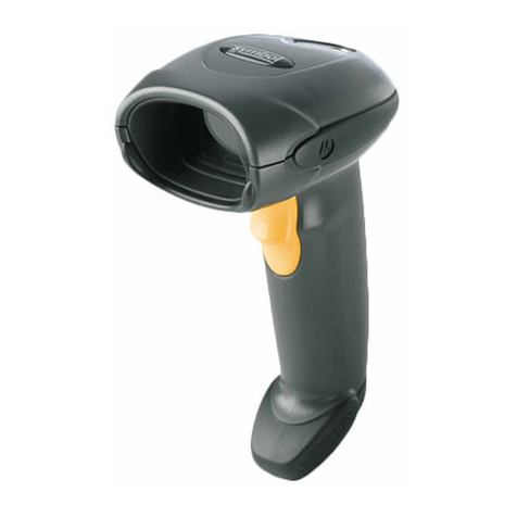
RJS D4000 SP1 Manual

D4000
Model SP1
Operator’s Guide
Manual P/N 002-5572
Release Version: A
August 2011
RJS Technologies
701 Decatur Ave North, Suite 107
Minneapolis, MN 55427
(763) 746-8034 Phone
(763) 746-8039 Fax
www.rjs1.com Website

Copyrights
The copyrights in this manual are owned by RJS Technologies, Inc. All rights are reserved.
Unauthorized reproduction of this manual or unauthorized use may result in imprisonment of up to one
year and fines of up to $10,000.00 (17 U.S.C. 506). Copyright violations may be subject to civil liability.
Reference RJS P/N 002-5572 Revision A (August 2011)
All right reserved.

Operator’s Guide Models D4000 SP1 InspectorTM
002-5572 iii RJS, Minneapolis, MN
TABLE OF CONTENTS
1.0 PREFACE 1
1.1 PROPRIETARY STATEMENT 1
1.2 STATEMENT OF FCC COMPLIANCE:USA 1
1.3 STATEMENT OF FCC COMPLIANCE:CANADA 1
1.4 CE: 1
1.5 DOCUMENTATION UPDATES 1
1.6 COPYRIGHTS 1
1.7 UNPACKING AND INSPECTION 1
1.8 INSTALLING BATTERIES 2
1.9 TECHNICAL SUPPORT 2
2.0 WARRANTY 3
2.1 GENERAL WARRANTY 3
2.2 WARRANTY LIMITATIONS 3
2.3 SERVICE DURING THE WARRANTY PERIOD 3
2.4 TRADEMARKS 3
3.0 INTRODUCTION 4
3.1 WARNINGS 4
3.2 MAINTENANCE 5
TEMPERATURE SPECS 5
3.3 D4000 SP1 DESCRIPTION AND FEATURES 5
FEATURES 5
4.0 THE LASER INSPECTOR 5
FIGURE 4-1 (D4000MODELSP1) 5
5.0 MAIN MENU SELECTIONS 6
5.1 SCAN 6
5.2 SETUP 7
5.3 STORAGE 11
5.4 STORAGE AND DATABASE 12
6.0 SCANNING SYMBOLS 14
7.0 PASS/FAIL ANALYSIS SCREEN 15

Model D4000 SP1 InspectorTM Operator’s Guide
RJS, Minneapolis, MN 002-5572
iv
TABLE 1(CODE IDENTIFIERS D4000 SP1) 16
TABLE 2(IDENTIFIER DESCRIPTIONS FOR PASS/FAIL ANALYSIS SCREENS) 16
8.0 DATA ANALYSIS SCREENS 18
ACCEPTABLE 20
WARNING 20
REJECTED 20
TABLE 3(LED, BARCODE WIDTH DEVIATIONS) 21
8.1 CONTINUOUS AND MULTI-SCAN MODES 22
9.0 CONNECT TO OTHER DEVICES 23
CONNECT TO COMPUTER 23
CONNECT TO PRINTER 23
CONTACT RJS FOR DETAILS: 23
APPENDIX A (CODE 128) 24
CODE 128 24
DISPLAY OF CODE 128 (RULES) 24
TABLE A-1 (CODE 128 —SUBSET A) 27
TABLE A-2 (CODE 128 —SUBSET B) 28
TABLE A-2 (CODE 128 —SUBSET B) 28
TABLE A-3 (CODE 128 —SUBSET C) 29
USS SHIPPING CONTAINER CODE (CASE CODE 128) 30
APPENDIX B (CODE 93) 31
CODE 93 31
TABLE B-1 (CODE 93 CHARACTER SET) 32
APPENDIX C (BATTERY DISPLAYS) 33
BATTERY DISPLAYS 33
APPENDIX D (MAGNIFICATIONS) 34
UPC/EAN MAGNIFICATIONS &BAR WIDTH DEVIATIONS 34
APPENDIX E (PRINT FUNCTIONS) 35
PRINT FUNCTIONS 35
PRINTOUT OPTIONS 35
ANALYSIS 35
STORAGE 35
FIGURE E-1 (CONTINUOUS SCAN) 36
FIGURE E-2 (MULTI-SCAN) 36

Operator’s Guide Models D4000 SP1 InspectorTM
002-5572 v RJS, Minneapolis, MN
APPENDIX F (SYMBOLOGY ANALYSIS) 37
SYMBOLOGY ANALYSIS PARAMETERS 37
TABLE F-1 (PARAMETER/ERROR MESSAGE) 37
TABLE F-2, (PARAMETERS CHECKED FOR EACH SYMBOLOGY) 38
APPENDIX G (ANSI DECODABILITY) 40
ANSI DECODABILITY CALCULATIONS 40
CODE 39 40
UPC/EAN 40
DECODABILITY GRADE CONVERSIONS 40
APPENDIX H (SCANNING TECHNIQUE) 41
SCANNING TECHNIQUE 41
SPECIAL CONSIDERATIONS 42
APPENDIX I (QUIET ZONE ANALYSIS) 43
QUIET ZONE ANALYSIS 43
TABLE I-1 (ACCEPTABLE PARAMETERS FOR SYMBOLS 43
WITHOUT ADDENDUMS) 43
TABLE I-2 (ACCEPTABLE PARAMETERS FOR SYMBOLS 43
WITH ADDENDUMS) 43
APPENDIX J 44
DOWNLOADING THE DATABASE 44
DATABASE SETUP 44
DATABASE RECORD 44
COMMUNICATION PARAMETERS 45
KEY FIELD DESCRIPTIONS 46
APPENDIX K 48
BARCODE DEFINITIONS 48


Operator’s Guide Model D4000 SP1 InspectorTM
002-5572 RJS, Minneapolis, MN
1
1.0 Preface
1.1 Proprietary Statement
The RJS Model D4000 SP1 Operator’s Guide contains proprietary information of RJS. It is intended solely
for the use of parties operating and maintaining the equipment described herein. This information may not
be used, reproduced, or disclosed to any other parties for any other purpose without the express written
permission of RJS.
1.2 Statement of FCC Compliance: USA
The equipment described in this manual has been tested and found to comply with the limits for a Class A
digital device, pursuant to Part 15 of the FCC Rules. These limits are designed to provide a reasonable
protection against harmful interference when the equipment is operated in a commercial environment. This
equipment generates, uses, and can radiate radio frequency energy and, if not installed and used in accord-
ance with this operator’s manual, may cause harmful interference to radio communications. Operating this
equipment in a residential area is likely to cause harmful interference in which case the user will be required
to correct the problem at his own expense.
1.3 Statement of FCC Compliance: Canada
This Class A digital apparatus meets all requirements of the Canadian interference-Causing Equipment
Regulations.
Cet appareil numénque de la classe A respecte toutes les exigences du Règlement sur le maténel brouilleur
du Canada.
1.4 CE:
This equipment generates, uses, and can radiate radio frequency energy and, if not installed and used in
accordance with this operator’s manual, may cause harmful interference to radio communications. Operating
this equipment in a residential area is likely to cause harmful interference in which case the user will be
required to correct the problem at his own expense.
1.5 Documentation Updates
RJS strives to provide the best possible documentation. This manual, or any of our manuals, may be updated
without notice.
1.6 Copyrights
The copyrights in this manual are owned by RJS Technologies, Inc. All rights are reserved. Unauthorized reproduc-
tion ofthis manual or unauthorized use ofthe software mayresult in imprisonment ofup to one year and fines ofup to
$10,000 (17 U.S.C.506). Copyright violations may be subject to civil liability.
1.7 Unpacking and Inspection
Carefully unpack the components and save the container. If the container is crushed, punctured or water
damaged save the container to prove a claim against the carrier. RJS is not responsible for transportation
damage.
Your D4000 SP1 is packaged in a custom made container. After removing the unit from the shipping box make
sure you have:
Main display unit
Laser Scanner
Alkaline size AA batteries (4)
Operator’s manual
Bar code “test” symbol sheet

Model D4000 SP1 InspectorTM Operator’s Guide
RJS, Minneapolis, MN 002-5572
2
1.8 Installing Batteries
Slide open the plastic cover on the back of the unit. Position the cloth battery “pull strip” down then insert 4
(included) batteries according to the positive/negative markings.
Note: If all 4 batteries are inadvertently installed backwards, the inspector unit will be damaged.
Remove batteries when the unit will not be used for a period of weeks. Also, remove batteries when storing
the unit.
Warning: Never charge alkaline batteriesthis will damage the unit.
1.9 Technical Support
Please read the manual and try to understand it, first.
If you need assistance over the phone, please have the following information ready:
Model and serial number of your unit
Do you have a maintenance contract in effect
Have a test print available if applicable
Detailed explanation of the problem or question
Your company’s phone and fax numbers
RJS
701 Decatur Avenue North
Suite 107
Minneapolis, MN 55427
(763) 746-8034 - phone
(763) 746-8039 - Fax

Operator’s Guide Model D4000 SP1 InspectorTM
002-5572 RJS, Minneapolis, MN
3
2.0 Warranty
2.1 General Warranty
Warranty information: (763) 746-8034
RJS warrants your D4000 SP1 to be free from defects in material and workmanship for a period of 1 year
from the date of shipment from RJS’ factory location.
The liability of RJS under this warranty is limited to repairing or replacing the defective part and/or unit.
RJS may optionally choose to issue credit for any unit returned during the warranty period.
You must promptly notify RJS of any defect in order to receive the full protection of this warranty.
2.2 Warranty Limitations
The warranty set forth above is exclusive and no other warranty, whether written or oral is expressed or
implied. RJS specifically disclaims the implied warranties of merchantability and fitness for a particular
purpose.
Some states or provinces do not allow limitation on how long an implied warranty lasts, so the above
limitation or exclusion may not apply to you. However, any implied warranty of merchantability or fitness is
limited to the one year duration of this written warranty.
RJS shall in no event be liable for any indirect, incidental, or consequential damages, including but not
limited to damages which may arise from loss of anticipated profits or production delivery delays,
spoilage of material, increased costs of operation of business or otherwise.
2.3 Service During The Warranty Period
If your D4000 SP1 should fail during the warranty period, contact RJS or its authorized representative
immediately upon discovery of the defect. A Return Authorization Number (RMA number) may be obtained
by visiting our website address: http://www.rjs1.com/request_rma.php
You will be asked to ship the product in its original packing, freight prepaid, with the RMA number visibly
written on the outside of the carton to RJS’ factory location.
Be sure to include any samples or printouts or other information that will help us to understand the problem.
Your repair will be given priority treatment, or your unit may be replaced at RJS’ option. The repaired item
will be returned UPS/RPS ground, freight prepaid.
At your request we will ship express or overnight if you need premium service and agree to pay the addi-
tional cost.
2.4 Trademarks
The following are trademarks of RJS:
RJS
RJS Systems International
D4000
Inspector Model D4000
SP1

Model D4000 SP1 InspectorTM Operator’s Guide
RJS, Minneapolis, MN 002-5572
4
3.0 Introduction
3.1 Warnings
Do not point the laser gun in the direction of the eyes so that the light beam emitted by the unit strikes
the eyes directlythis could result in eye damage.
Keep the unit and gun away from a water source such as a faucetthis could short the unit and cause
injury.
Users of the verifier (unit and gun) are not authorized to open case(s) or in any way modify circuitry.
The following caution labels should already be on the laser gun (and must remain on the laser gun):
LASER LIGHT - DO NOT STARE INTO BEAM
EMITTED WAVELENGTH 630-680nm
MAX. OUTPUT RADITATION 1.0mW
CLASS 2 LASER PRODUCT EN 60825-
1:2007
This product complies with 21 CFR Subchapter J
CLASS 2 LASER LIGHT WHEN OPEN AVOID
EXPOSURE - LASER LIGHT IS EMITTED FROM
THIS APERTURE - DO NOT STARE INTO BEAM
!
This equipment complies with the requirements in part 15
of FCC rules for a class A computing device. Operation
of this equipment in a residential area may cause
interference in radio and TV reception, requiring the
operator to take whatever steps are necessary to correct
the interference.
Class II laser product.
This product conforms to DHMS
regulation 21 CFR subchapter J for
use with listed class II EDP equipment
Not user serviceable. Opening case voids warranty.
If a caution
label(s) with
equivalent
information as
shown on the
examples to the
right are not on
the laser gun,
notify RJS at
once.

Operator’s Guide Model D4000 SP1 InspectorTM
002-5572 RJS, Minneapolis, MN
5
3.2 Maintenance
To ensure the best possible scanning conditions, keep the laser window and display clean. Use a soft, damp,
lint-free cloth to clean scanner window.
Do not use solvents on the unit or on any of the components. You may use alcohol to clean the unit.
Temperature Specs
Do not operate or store your unit or components in temperatures outside the range of 50° - 105°. Do not
operate or store your unit in conditions of high humidityover 80%.
3.3 D4000 SP1 Description and Features
The Model D4000 SP1 are advanced technology barcode verifiers that make it easy to decode barcode symbols and
to evaluate symbol compliance with industry specifications. The Model D4000 SP1emits a very precise laser light
that provides veryaccurate scan analysis; these units do not, however, provide PCS analysis. See
Figure 4-1 (D4000 SP1)
Features
ON button initiates scanning
Automatic power-down after short period of disuse
Automatic print mode
Database lookup function
Can scan curved surfaces
Barcode symbol data and deviation displays
Visual and audible signals
Low battery indicator
Store and print capabilities
Multiple scan averaging
Auto-discriminates between many different symbologies
Serial interface permits analysis data to be printed on an optional RJS portable printer
4.0 The Laser Inspector
Figure 4-1 (Model D4000 - SP1 )

Model D4000 SP1 InspectorTM Operator’s Guide
RJS, Minneapolis, MN 002-5572
6
5.0 Main Menu Selections
Note: Even though your Inspector may have a 4 row display, only 2 are currently used and only 2 are shown in the examples.
After turning on the unit, the “Ready Menu” will display:
L1000 Rev. X.XX
Ready
X.XX Current Revisions of Software
Press Enter and Select at the same time to bring up the Main Menu:
SCAN SETUP
DATABASE/STORAGE
Note: For all menu displays, toggle through the choices by pressing Select. Accept the selection by pressing Enter.
5.1 Scan
Select Scan (from the Main Menu) to display the initial Pass/Fail Analysis screen for the previously scanned
barcode.
Note: A barcode can be scanned at any time except when the unit is printing.
Note: When scanning any barcode, the surrounding background should be the same color as the barcode background. For
example, if your scan is picking up part of a dark table top, slip a white piece of paper under the bar code to assure a
good read.

Operator’s Guide Model D4000 SP1 InspectorTM
002-5572 RJS, Minneapolis, MN
7
5.2 Setup
Select Setup (from the Main Menu) to set various system parameters:
D/bility Warning
D
Select an ANSI decodability grade to use in your analysis (See Appendix G for an explanation of the grades.)
A warning message will be produced for the selected grade or any lower grades:
B C D F NONE
Press Select to scroll the choices for warning threshold grade
Press Enter to initiate processing for that option
If NONE is selected, the decodability grade will not be used to trigger a warning message. However, the
decodability grade will be calculated and available for viewing.
The next selection allows selection from a range of UPC/EAN symbol magnifications:
UPC/EAN tol.
90 - 115% Mag.
The magnifications selections are:
(See Appendix D for an explanation of magnifications.)
80 - 89 % Mag
90 - 115 % Mag
116 - 150 % Mag
151 - 200 % Mag
The next selection is;
UPC/EAN Rnd. Wt.
OFF
Note: Select ON to activate UPC/EAN random weight check digit calculations. (See Appendix F)
Press Select to scroll the choices
Press Enter to initiate processing for that option
The next selection is Decode 3of 9 as:
Decode 3of 9 as
ANSI 3of 9
This selection is for choosing the Code 39 sub-specifications to be analyzed:
ANSI 3 of 9
3of9 w/43
AIAG B-1
AIAG B-3/4/5
LOGMARS

Model D4000 SP1 InspectorTM Operator’s Guide
RJS, Minneapolis, MN 002-5572
8
HIBC 3 of 9
The next selection is:
Decode I 2of 5
ANSI I 2 of 5
This allows a selection from 2 types of Interleaved 2 of 5:
ANSI I 2 of 5
Case Code
The next selection is:
Auto Print Mode
Off
Note:Select ON to activate the automatic printing mode; analysis data will print after each scan and the LCD will display
“Printing Scan Analysis.” (See Appendix E)
The next selection is:
Printer Type
TP 140
Selections are: TP40, TP140, or Computer.

Operator’s Guide Model D4000 SP1 InspectorTM
002-5572 RJS, Minneapolis, MN
9
The next selection is :
Database Storage
XX kb XX kb
Enter the percentages. (See the following note.)
Note: Storage and Database buffers are two separate areas but each shares a total of 20K of memory. For example, if 5K of
memory is used for Storage, the Database buffer will have 15K. If 15K of memory is used by the Database, Storage
will have 5K. Allocations are made in blocks of 5K.
The next selection is:
Scans/Analysis
XXXXX
From this screen choose the number of scans (from 2 to 10) to be used in the analysis. Or Select “Single” for
a single scan, or “Continuous” for continuous scanning.
See 8.1 Continuous and Multi-scan modes

Model D4000 SP1 InspectorTM Operator’s Guide
RJS, Minneapolis, MN 002-5572
10
The last menu setup selection is:
Comparison Mode
OFF
Note: Comparison Mode is not accessed if “Continuous” scans/analysis mode is enabled.
Selecting ON in the Comparison Mode causes the next scanned symbol to be the “target.” A “No Match”
will display when subsequent symbols do not match the “target.”
To generate a new “target” while remaining in the Comparison Mode, toggle the Comparison Mode selec-
tion to OFF and then to ON again.
When all Setup selections have been made, the D4000 SP1 will navigate back to the Main Menu automati-
cally.
Note: All setup parameters are retained in non-volatile memory and will be saved until changed by you—even after
the power is turned off.

Operator’s Guide Model D4000 SP1 InspectorTM
002-5572 RJS, Minneapolis, MN
11
5.3 Storage
Storage is used to hold scan data for future print or review. Up to approximately 75 barcodes may be held in
storage.
From the main menu press Enter and Select at the same time the following will be displayed.
Scan Setup
Database/Storage
Select Database and press Enter
The display will show either “Storage Inactive” or “Storage %.”
Database Empty
Storage Inactive
Store and Print is inactive
Scan Setup
Storage XX%
Store and Print is active
If a % is displayed, it represents the percentage of the buffer that is filled with scan data.
You may enable or disable Store and Print by pressing Enter with the cursor on Storage. (Toggle from one
option to the other.)
When Storage is active, press Select to move the cursor to the % sign. Press Enter on the % sign to clear
the Store and Print buffer.

Model D4000 SP1 InspectorTM Operator’s Guide
RJS, Minneapolis, MN 002-5572
12
5.4 Storage and Database
A special serial interface cable that connects to your personal computer is available (Part Number 002-
2979).
The Database function is used to validate barcode data or compare barcode data to a pre-defined description
that is placed into the database. When using the Database function the barcodes that are scanned must be in
the database on the D4000 SP1; otherwise, the following message will display (unless the database function
is turned off):
Data Base Record
Does Not Exist
The Model D4000 SP1 contains 20K of memory that is used by Storage and the Database. All or part of this
20K can be used by the Database (the remainder is used as Storage).
With the D4000 SP1, a database file can be created on a PC. The file consists of barcode data and display
messages (described later in this section). Download this database (using a serial communication port) from
the PC to the Inspector unit. Scans may then be performed.
As a barcode is scanned, the Inspector unit’s database is searched for a match. When a match is found, the
message from the database (that was previously entered) will display along with the verification analysis.
The Storage function is used to hold barcode data, to be printed or reviewed later. Up to approximately 75
barcodes may be held in storage.
Please note that Database and Storage percentages are allocated in the Setup menus explained in a previous
section.
The database function is defaulted to OFF and becomes active when data is placed in the database. The
storage function is activated or deactivated in the Database/Storage menus explained in this section.
SCAN SETUP
DATABASE/STORAGE
Press Select until the cursor is on the Database/Storage option
Press Enter to initiate the option

Operator’s Guide Model D4000 SP1 InspectorTM
002-5572 RJS, Minneapolis, MN
13
Database XX
Storage YY
The cursor will be on the “D” in database.
The “Xs” in the above sample represent one of the following displays for the database:
EMPTY (There is no data in the database buffer)
XX% (Percentage of active database buffer that is filled, 0 - 99%)
The “Ys” in the above sample represent one of the following displays for storage:
Inactive (Store and Print buffer not enabled)
YY% (Percentage of active storage buffer that is filled, 0 - 99%)
0 KB (No storage was reserved in the Setup procedure)
With the cursor on Storage, press Enter to toggle the Storage function between enabled and disabled.
When Storage is activated, by pressing Select, the cursor will position to the percentage sign (%). To clear
the storage buffer, press Enter with the cursor on the % sign00% will display. (Press Enter again if you
cleared the buffer by mistake.)
Press Select again to return to the Main Menu.
Note: For an explanation about printing the contents of the Store and Print buffer See Appendix E.
Note: Deactivating the database function does not alter the contents of the database buffer. See Appendix J (Downloading
Data).

Model D4000 SP1 InspectorTM Operator’s Guide
RJS, Minneapolis, MN 002-5572
14
6.0 Scanning Symbols
To scan a barcode simply pull the trigger and position the beam across the symbol. A crisp, clear chirp (or
beep) sound will indicate a good read. See Appendix H for details.
Decoded data and symbology type will display:
*01928374*
ANSI I 2 of 5
Press Enter to navigate to the Pass/Fail Analysis screen, then begin pressing Select to scroll through the
analysis screens.
ANSI I 2 of 5
Acceptable
(See Pass/Fail Analysis Screen section)
Table of contents
Other RJS Barcode Reader manuals
