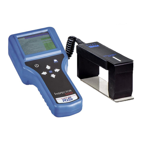
RJS Inspector 4000 Manual

Inspector 4000™Operator’s Guide
ii RJS, Minneapolis, MN
Copyrights
The copyrights in this manual are owned by RJS. All rights are reserved.
Unauthorized reproduction of this manual or unauthorized use of the Inspector 4000
software may result in imprisonment of up to one year and fines of up to $10,000.00
(17 U.S.C. 506). Copyright violations may be subject to civil liability.
Reference RJS P/N 002-5564 Revision D
All Rights Reserved.

Operator’s Guide Inspector 4000™
002-5564 RJS, Minneapolis, MN
i
TABLE OF CONTENTS
1.0 PREFACE 1
1.1 PROPRIETARY STATEMENT 1
1.2 STATEMENT OF FCC COMPLIANCE:USA 1
1.3 STATEMENT OF FCC COMPLIANCE:CANADA 1
1.4 CE: 1
1.5 DOCUMENTATION UPDATES 2
1.6 COPYRIGHTS 2
1.7 UNPACKING AND INSPECTION 2
1.8 INSTALLING BATTERIES 2
1.9 TECHNICAL SUPPORT 3
2.0 WARRANTY 4
2.1 GENERAL WARRANTY 4
2.2 WARRANTY LIMITATIONS 4
2.3 SERVICE DURING THE WARRANTY PERIOD 5
2.4 TRADEMARKS 5
3.0 INTRODUCTION 6
3.1 INSPECTOR 4000 DESCRIPTION AND FEATURES 6
FEATURES 6
3.2 MAINTENANCE 6
3.3 TEMPERATURE SPECS 7
4.0 THE INSPECTOR 4000 8
FIGURE 4-A (INSPECTOR 4000) 8

Operator’s Guide Inspector 4000™
002-5564 RJS, Minneapolis, MN
ii
5.0 MAIN MENU SELECTIONS 9
5.1 CALIBRATION 9
POWER ON9
VERIFYING THAT UNIT IS CALIBRATED 10
CALIBRATING THE UNIT 10
5.2 SCAN 11
5.3 SETUP 13
5.4 STORAGE 17
6.0 PCS ANALYSIS 18
PCS SCANNING (OVERVIEW) 18
7.0 SCANNING SYMBOLS 19
7.1 SCANNING TECHNIQUES 19
8.0 PASS/FAIL ANALYSIS SCREEN 20
TABLE 8-A (CODE IDENTIFIERS INSPECTOR 4000 ) 21
TABLE 8-B (CODE IDENTIFIER DESCRIPTIONS FOR
PASS/FAIL ANALYSIS SCREEN) 22
9.0 DATA ANALYSIS SCREENS 23
ACCEPTABLE 27
WARNING 27
REJECTED 27
TABLE 9-A (LED, BAR-CODE WIDTH DEVIATIONS) 28
ANSI ANALYSIS SCREENS 29
10.0 CONNECT TO OTHER DEVICES 31

Operator’s Guide Inspector 4000™
002-5564 RJS, Minneapolis, MN
iii
CONNECTION TO OTHER DEVICES 31
CONNECT TO COMPUTER 31
CONNECT TO PRINTER 31
APPENDIX A (CODE 128) 32
CODE 128 32
DISPLAY OF CODE 128 (RULES) 33
TABLE A-1 (CODE 128 —SUBSET A) 35
TABLE A-2 (CODE 128 —SUBSET B) 36
TABLE A-3 (CODE 128 —SUBSET C) 37
USS SHIPPING CONTAINER CODE (CASE CODE 128) 38
APPENDIX B (CODE 93) 39
CODE 93 39
TABLE B-1 (CODE 93 CHARACTER SET) 41
APPENDIX C (COMMUNICATION FORMAT) 42
COMPUTER MODE 42
ANALOG SCAN PROFILE 42
FIGURE C-1 43
APPENDIX D (BATTERY DISPLAYS) 44
BATTERY DISPLAYS 44
APPENDIX E (MAGNIFICATIONS) 45
UPC/EAN MAGNIFICATIONS &BAR WIDTH DEVIATIONS 45
APPENDIX F (PRINT FUNCTIONS) 46

Operator’s Guide Inspector 4000™
002-5564 RJS, Minneapolis, MN
iv
PRINT FUNCTIONS 46
PRINTOUT OPTIONS 46
ANALYSIS 46
ANALYSIS AND PROFILE 46
STORAGE 47
FIGURE F-1 (SEE FIGURE C-1 ALSO) 47
APPENDIX G (SYMBOLOGY ANALYSIS) 48
SYMBOLOGY ANALYSIS PARAMETERS 48
TABLE G-1 (PARAMETER/ERROR MESSAGE) 48
TABLE G-2 (PARAMETERS CHECKED FOR EACH
SYMBOLOGY) 49
APPENDIX H (ANSI DECODABILITY) 51
ANSI DECODABILITY CALCULATIONS 51
DECODABILITY GRADE CONVERSIONS 51
APPENDIX I (QUIET ZONE ANALYSIS) 52
QUIET ZONE ANALYSIS 52
TABLE I-1 (ACCEPTABLE PARAMETERS FOR SYMBOLS 52
WITHOUT ADDENDUMS) 52
TABLE I-1 CON...(ACCEPTABLE PARAMETERS FOR
SYMBOLS WITH ADDENDUMS) 53
APPENDIX J 54
INSPECTOR 4000 ANALYSIS PARAMETERS 54
REFERENCE DECODE 54
DECODABILITY 55
SYMBOL CONTRAST 55
REFL (MIN)/REFL (MAX) 56

Operator’s Guide Inspector 4000™
002-5564 RJS, Minneapolis, MN
v
EDGE CONTRAST (MIN) 56
MODULATION 56
TRADITIONAL ANALYSIS TOLERANCE GRAPH 58
APPENDIX K 59
BAR-CODE DEFINITIONS 59

Operator’s Guide Inspector 4000™
002-5564 RJS, Minneapolis, MN
1
1.0 Preface
1.1 Proprietary Statement
The RJS Inspector 4000 Operator’sGuide contains proprietary information of RJS. It is
intended solely for the use of parties operating and maintaining the equipment described
herein. This information may not be used, reproduced, or disclosed to any other parties
for any other purpose without the express written permission of RJS.
1.2 Statement of FCC Compliance: USA
The equipment described in this manual has been tested and found to comply with the
limits for a Class A digital device, pursuant to Part 15 of the FCC Rules. These limits are
designed to provide a reasonable protection against harmful interference when the
equipment is operated in a commercial environment. This equipment generates, uses, and
can radiate radio frequency energy and, if not installed and used in accordance with this
operator’s manual, may cause harmful interference to radio communications. Operating
this equipment in a residential area is likely to cause harmful interference in which case
the user will be required to correct the problem at his own expense.
1.3 Statement of FCC Compliance: Canada
This Class A digital apparatus meets all requirements of the Canadian interference-
Causing Equipment Regulations.
Cet appareil numénque de la classe A respecte toutes les exigences du Règlement sur le
maténel brouilleur du Canada.
1.4 CE:
This equipment generates, uses, and can radiate radio frequency energy and, if not
installed and used in accordance with this operator’s manual, may cause harmful
interference to radio communications. Operating this equipment in a residential area is
likely to cause harmful interference in which case the user will be required to correct the
problem at his own expense.

Operator’s Guide Inspector 4000™
002-5564 RJS, Minneapolis, MN
2
1.5 Documentation Updates
RJS strives to provide the best possible documentation. This manual, or any of our
manuals, may be updated without notice.
1.6 Copyrights
The copyrights in this manual are owned by RJS. All rights are reserved. Unauthorized
reproduction of this manual or unauthorized use of the software may result in
imprisonment of up to one year and fines of up to $10,000 (17 U.S.C.506). Copyright
violations may be subject to civil liability.
1.7 Unpacking and Inspection
Carefully unpack the components and save the container. If the container is crushed,
punctured or water damaged you can use the container to prove a claim against the
carrier. RJS is not responsible for transportation damage.
Your Inspector 4000 is packaged in a custom made container. After removing the unit from the
shipping box make sure you have:
Main display unit
Auto-optic scan head and cable
Four size AA batteries
Operator’s manual
Bar-code “test”symbol sheet
1.8 Installing Batteries
Slide open the plastic cover on the back of the unit. Position the cloth battery “pull strip”
down then insert 4 (included) batteries according to the positive/negative markings.

Operator’s Guide Inspector 4000™
002-5564 RJS, Minneapolis, MN
3
Note: If all 4 batteries are inadvertently installed backwards, the inspector unit will be damaged.
Remove batteries when the unit will not be used for a period of weeks. Also, remove
batteries when storing the unit.
Note: NiCad batteries and charger are available as options.
Warning: When using the optional charger, DO NOT charge alkaline batteriesthis will damage to
the unit.
1.9 Technical Support
Please read the manual and try to understand it, first.
If you need assistance over the phone, please have the following information ready:
Model and serial number of your unit
Do you have a maintenance contract in effect
Have a test print available if applicable
Detailed explanation of the problem or question
Your company’s phone
RJS
701 Decatur Avenue North, Suite 107
Minneapolis, MN 55427
(763) 746-8034 - phone

Operator’s Guide Inspector 4000™
002-5564 RJS, Minneapolis, MN
4
2.0 Warranty
2.1 General Warranty
Warranty information: (763) 746-8034
RJS warrants your Inspector 4000 to be free from defects in material and workmanship
for a period of 1 year from the date of shipment from RJS’factory location.
The liability of RJS under this warranty is limited to repairing or replacing the defective
part and/or unit. RJS may optionally choose to issue credit for any unit returned during
the warranty period.
You must promptly notify RJS of any defect in order to receive the full protection of this
warranty.
2.2 Warranty Limitations
The warranty set forth above is exclusive and no other warranty, whether written or oral is
expressed or implied. RJS specifically disclaims the implied warranties of merchantability
and fitness for a particular purpose.
Some states or provinces do not allow limitation on how long an implied warranty lasts,
so the above limitation or exclusion may not apply to you. However, any implied
warranty of merchantability or fitness is limited to the one year duration of this written
warranty.
RJS shall in no event be liable for any indirect, incidental, or consequential damages,
including but not limited to damages which may arise from loss of anticipated
profits or production delivery delays, spoilage of material, increased costs of operation of
business or otherwise.

Operator’s Guide Inspector 4000™
002-5564 RJS, Minneapolis, MN
5
2.3 Service During The Warranty Period
If your Inspector 4000 should fail during the warranty period, contact RJS or its
authorized representative immediately upon discovery of the defect. A Return
Authorization Number (RMA number) may be obtained by visiting our website address:
http://www.rjs1.com/request_rma.php
You will be asked to ship the product in its original packing, freight prepaid, with the
RMA number visibly written on the outside of the carton to RJS’factory location.
Be sure to include any samples or printouts or other information that will help us to
understand the problem. Your repair will be given priority treatment, or your unit may be
replaced at RJS’option. The repaired item will be returned UPS/RPS ground, freight
prepaid.
At your request we will ship express or overnight if you need premium service and agree
to pay the additional cost.
2.4 Trademarks
The following are trademarks of RJS:
RJS
RJS Systems International
Inspector 4000

Operator’s Guide Inspector 4000™
002-5564 RJS, Minneapolis, MN
6
3.0 Introduction
3.1 Inspector 4000 Description and Features
The Inspector 4000 is an advanced technology bar-code verifier that makes it easy to
decode bar-code symbols and to evaluate symbol compliance with industry standards.
See Figure 4-A (Inspector 4000).
Features
Four aperture sizes selectable from setup menu
Two light wavelengths selectable from setup menu
Provides scan head light color and aperture size
(display/print)
Auto-discriminates between many different
symbologies
Auto-print mode
Bi-directional scanning
Calculate and display print contrast signals (PCS)
Low battery indicator
Multiple scan averaging
Power-down is automatic after short period of disuse
Programmable, multi-scan analysis
Specially designed wand ensures accurate scanning
angle
Store and print capabilities
Visual and audible signals
3.2 Maintenance
To ensure the best possible scanning conditions, keep the display window clean. Use a
soft, damp, lint-free cloth to clean the window.
Do not use solvents on the unit or on any of the components. You may use alcohol to
clean the unit.

Operator’s Guide Inspector 4000™
002-5564 RJS, Minneapolis, MN
7
3.3 Temperature Specs
Do not operate or store your unit or components in temperatures outside the range of 50°
- 105°. Do not operate or store your unit in conditions of high humidityover 80%.

Operator’s Guide Inspector 4000™
002-5564 RJS, Minneapolis, MN
8
4.0 The Inspector 4000
Figure 4-A (Inspector 4000)
Auto-optic scan head
LCD
window
5 indicator
LED’s
Function
buttons
Battery Charger
Serial interface
Calibration plaque is a
separate component

Operator’s Guide Inspector 4000™
002-5564 RJS, Minneapolis, MN
9
5.0 Main Menu Selections
5.1 Calibration
Power On
When the unit is powered on, the following “Ready Menu”will display after a few
seconds:
Verifier Ready
XXX Aperture: YY
XXX = indicates the wavelength (color) of the light represented in nanometers
YY = indicates the aperture size in mils
Example: 660 Aperture: 10
This display indicates that the installed wand uses red
light at 660 Nanometer wavelength and a 10 mil diameter
aperture size.
Press Enter and Select at the same time to bring up the Main Menu:
Scan Calib Setup
Storage Inactive
I4000 Ver.x.xx
x.xx = Indicates the Software Version.
Press Select until the cursor is on CALIB and press Enter.
Inspector 4000
Reflectance XX%

Operator’s Guide Inspector 4000™
002-5564 RJS, Minneapolis, MN
10
Verifying that Unit is Calibrated
Selecting CALIB sets up the mode to measure reflectance. This also allows you to
check the calibration of the unit by placing the wand on a template (white or black
field) and verifying that the reflectance value matches the stated values.
Verify that reflectance values are within 5% for white and 2% for black. If the values
are not within these tolerances you need to calibrate the unit; otherwise, press Enter
and Select at the same time to navigate back to the Main Menu.
Calibrating the Unit
After selecting Calib from the main menu, the reflectance menu will display.
Inspector 4000
Reflectance XX%
From the reflectance menu press Enter, the Calibrate menu will display:
Calibrate
When the “Calibrate”menu is displayed, proceed with the following calibration steps:
Place Optics on
White/Enter Key
Place the wand on the white section of the calibration plaque with the shoe guide flat
against the surface. Press Enter and hold auto-optic scanner head still until you hear a
“chirp”sound.

Operator’s Guide Inspector 4000™
002-5564 RJS, Minneapolis, MN
11
Place Optics on
Black/Enter Key
Place the wand on the black section of the calibration plaque with the shoe guide flat
against the surface. Press Enter and hold auto-optic scanner head still until you hear a
“chirp”sound.
When both light and dark have been calibrated the following screen will display:
Calibrated
Reflectance XX%
Verify that the unit is calibrated by again placing the scan head on the light or dark area of
the plaque.
The reflectance % value will display. Reflectance values should be within 5% (of the
known value of the plaque) for white and 2% (of the known value of the plaque) for black.
If the “Unable to Calibrate”screen displays, repeat the calibration.
Unable to
Calibrate
Note: Power drain is greatest in the calibration mode. The automatic shut-off feature is disabled in
calibration mode. Once the unit is calibrated, the calibration data will remain in memory;
however, you should calibrate the unit at the beginning of each day or each shift for the proper
PCS readings.
5.2 Scan
After finishing calibration press Select and Enter at the same time; the “Ready Menu”
will display:

Operator’s Guide Inspector 4000™
002-5564 RJS, Minneapolis, MN
12
Scan Calib Setup
Storage Inactive
In addition to CALIB, explained in the previous section, there are 3 additional
“selectable”functions: Scan, Setup and Storage:
Press Select to choose an option.
Press Enter to initiate processing for that option.
Select Scan (from the Main Menu) to display the initial Pass/Fail Analysis screen for the
previously scanned bar code.
Note: A bar code can be scanned at any time except when the unit is printing.
Note: When calibrating the unit or when scanning any bar-code, the background must be the same
color as the bar-code back- groundin the case of the included test symbol sheet the
background should be white.
For example, if your scan is picking up part of a dark table top, slip a white piece of paper
under the bar-code to assure a good read.

Operator’s Guide Inspector 4000™
002-5564 RJS, Minneapolis, MN
13
5.3 Setup
Select Setup (from the Main Menu) to view various system parameters:
Wavelength
This selection allows you to select one of two light wavelengths; toggle the two choices
by pressing Select.
Wavelength
660nm, Red
Wavelength
925nm, Infra-Red
Press Enter to enable the selection.
Aperture Size
.10 in.
After selecting Wavelength and pressing Enter, select the Aperture size:
.003 in.
.005 in.
.010 in.
.020 in.
The next selection is “Passing Grade.”
Passing Grade
B
Select one of the threshold grades, A, B, C, or D.
Table of contents
Other RJS Barcode Reader manuals

