manuals.online logo
Brands
  1. Home
  2. •
  3. Brands
  4. •
  5. RKC INSTRUMENT
  6. •
  7. Media Converter
  8. •
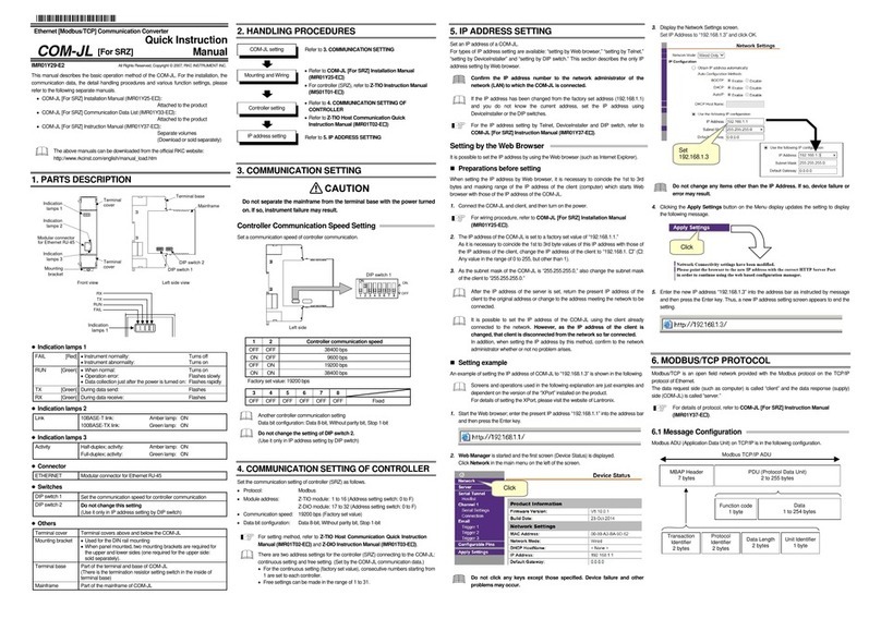
  9. RKC INSTRUMENT COM-103C User manual

RKC INSTRUMENT COM-103C User manual

COMMUNICATION LEVEL CONVERTER FOR
RS-232C/RS-422A(RS-485)
COM-103C
INSTRUCTION MANUAL
IMCOM04-E3
Thank you for purchasing this COM-103C. Before using this
product, please carefully read this manual for its correct use. In
addition, after reading the manual keep it available easily
anytime.
z
Wiring precautions
• If failure or error of this instrument could result in a critical
accident of the system, install an external protection circuit
toprevent such an accident.
• In order to prevent instrument damage or failure, protect the
power line and the input/output lines from high currents by
using fuses with appropriate ratings.
z
Power supply
• In order to prevent instrument damage or failure, supply
power of the specified rating.
• In order to prevent electric shock or instrument failure, do
not turn on the power supply until all of the wiring is
completed.
z
Installation environment
In order to prevent fire, explosion or instrument damage,
never use this instrument at a location where inflammable or
explosive gases or vapour exist.
z
zz
z
Never touch the inside of the instrument.
In order to prevent electric shock or burns, never touch the
inside of the instrument. Only RKC service engineers can
touch the inside of the instrument to check the circuit or to
replace parts. High voltage and high temperature sections
inside the instrument are extremely dangerous.
z
Never modify the instrument.
In order to prevent accident or instrument failure, never modify
the instrument.
z
Maintenance
• In order to prevent electric shock, burns or instrument
failure, only RKC service engineers may replace parts.
• In order to use this instrument continuously and safely,
conduct periodic maintenance. Some parts used in this
instrument have a limited service life and may deteriorate
with time.
1. NAME OF PARTS AND TERMINALS
RS-232C
1
A
B
COM-103C
2
3
4
5
6
7
8
9
2. MOUNTING
2.1 Mounting cautions
Avoid the following when selecting the mounting location.
z
Ambient temperature of less than 0 °C (32 °F) or more than 50 °C
(122 °F).
z
Ambient humidity of less than 45 % or more than 85 % RH.
z
Rapid changes in ambient temperature which may cause
condensation.
z
Corrosive or inflammable gases.
z
Direct vibration or shock to the mainframe.
z
Water, oil, chemicals, vapor or steam splashes.
z
Excessive dust, salt or iron particles.
z
Excessive induction noise, static electricity, magnetic fields or noise.
z
Direct air flow from an air conditioner.
z
Should be used indoors where the system is not exposed to direct
sunlight.
z
Heat to be accumulated radiation heat.
2.2 Mounting method
Rack mounting type (COM-103C-R)
cMake cutouts in the panel corresponding to the number of
converters to be mounted by referring to panel cutout dimensions.
dInsert the converter into the cutout from the panel front.
eUsing a Phillips screwdriver, secure the converter from the terminal
side with 2 setscrews (M4×6 SEMS pan-head screw).
Screws provided by customer.
32(1.26) 21
(0.83) 89(3.50)
2-M4
210
(
8.27
)
198
(
7.80
)
181.8
(
7.16
)
198 ±0.2( 7.795±0.007
)
182.
5
+0.3
0( 7.185+0.011
0
)
φ
4.2
(
0.17
)
32.5+0.2
0( 1.280 0
+0.007 )
[
[[
[unit :
:::mm (inch)]
]]
]



Panel cutout
Dimensions
Wall mounting type (COM-103C-W)
cDrill holes corresponding to the number of converters to be
mountedby referring to panel cutout dimensions.
dUsing a Phillips screwdriver, secure the converter from the
terminalside with 2 setscrews (M4×6 SEMS pan-head screw).
Screws provided by customer.
32(1.26) 111(4.37)
90(3.54)
2-M4
210(8.27)
198(7.80)
181.8(7.16)
198 ±0.2 ( 7.79
5
±0.007 )
φ4.2(0.17)
[
[[
[unit :
:::mm (inch)]
]]
]



Panel cutout
Dimensions
3. WIRING
3.1 Cautions for wiring
(1) Conduct input signal wiring away from instrument power,
electricequipment power and load lines to avoid noise induction.
(2) For power supply wires, use twisted wires with low voltage drop.
(3) Do not excessively tighten the terminal screws. In addition, use the
solderless terminal appropriate to the screw size. (Screw size:
M3×6, recommended tightening torque: 0.5 Nxm [5 kgfxcm])
WARNING
Name of parts
A: Power lamp
B: Connector for RS-232C Interface
Terminals
Terminal
s
Contents
1
2
3
SG Communication
terminals
T/R(A) RS-422A or RS-485
T/R(B)
4
5
6
Unused
7
8
Power supply voltage terminals
90 to 264 V AC
9Ground terminal
SG : Signal Ground
T/R(A):TransmissionTerminal(A)
T/R(B):TransmissionTerminal(B)
φ
3.2(0.13)
φ
3.2(0.13)
φ
4.3
(0.17)
11.3(0.44)
Unit: mm (inch)
9.0 (0.35)
18.6
(0.73)
Ring type
solderless terminal
4.3(0.17)
Spade type
solderless terminal
7.2
(
0.28
)
7.4
(0.29)
φ
6.6 (0.26)
(4) This instrument has no power supply switch nor fuses. Therefore,
install the fuse close to the instrument and the switch, if required.
Fuse type : Time-lag fuse
Recommended fuse rating : Rated voltage : 250 V
Rated current : 1 A
(5) Conduct instrument power wiring so as not to be influenced by
noise from the electric equipment power. If the instrument may be
affected by external noise, a noise filter should be used.
yShorten the distance between twisted power supply wire pitches.
The shorter the distance between the pitches, the more effective for
noise reduction.
yInstall the noise filter on the panel which is always grounded and
minimize the wiring distance between the noise filter output side
and the instrument power terminals.
OUT
Minimize
distance
power
terminals
IN
Twist these leadwires
Shorten distance between
pitches
Instrument power
Noise filter
yDo not install fuses and/or switches on the filter output signal since
this may lessen filter effect.
3.2 Solderless terminal
Space of fitting a solderless terminal is 7.4 mm×11.3 mm. Therefore,
use the solderless terminal suitable for a screw of M3. A free terminal
screw of M3×6 is used.
When the instrument is installed in a location where much
vibration and shock exist, use ring type compression lugs,
since spade type compression lugs may be desconnected from
the terminals.
4. CONNECTION
4.1 Connection method
This device supports communications between the RS-232C and RS-
422A or RS-485 interfaces.
■Connection procedure of host computer
Host computer and COM-103C are connected by a cable for RS-
232C (Using the connector).
cLoosen the plug case screws, connect the cable core wires to the
relevant connector pins, and mate the plug case with the wired
connector before tightening the screws with a screwdriver.
dPlug the communication connector connected with the cable cinto
the instrument connector (See the terminal plate diagram.)
eThen, using a screwdriver, secure the connector with 2 upper and
lower screws.
Communication cable for RS-232C
Host Computer COM-103C
SD
RD
RS
CS
SG SG
CS
RS
RD
SD
2
3
4
5
7
2
3
4
5
7
Accessories
Connector …HDBB-25P (Hirose Electric Co., Ltd. or equivalent)
Plug case …HDB-CTF (Hirose Electric Co., Ltd. or equivalent)
■Connection procedure of controller
COM-103C and controller are connected by a twisted pair wire
(shielded). (Using the terminals #1, #2, #3 of COM-103C.)
The twisted pair wire should be prepared by the user.
For details of connection procedure, see the communications
instruction manual for using RKC′s controller.
RKC′s
controller
RS-422A or RS-485
SG
T/R(A)
T/R(B)
Twisted pair w ire
(w ith s hield) COM-103C
RS-232C
Twisted pair w ire
(w ith s hield)
Host Computer
1
2
3
9
SG
FG
T/R(A)
T/R(B)
*R
*R : Use a term inal resistor with a combined resistance of more than 100 Ω.
Paired wire
4.2 Multidrop connection example
If branched with our instrument BRA-100B, the transmission distance
between COM-103C and BRA-100B may be extended to some degree
and multidrop connection becomes possible. The number of controllers
that can be connected depends on the controller being used.
For details of RKC′s BRA-100B, see the instruction manual.
Host Computer
RS-232C
COM-103C
BRA-100B BRA-100B BRA-100B
RS-422A or RS-485
RKC′s
controller
RKC′s
controller
RKC′s
controller
RKC′s
controller
14
23
14
23 32
14
3
1 2 4 2930
31
4.3 Internal Connection
RS-232C
Host Computer COM-103C
SD
RD
RS
CS
SG
3
2
5
7
RD
SD
CS
SG
T/R(A)
(term inal No.2)
T/R(B)
(term inal No.3)
SG
(term inal No.1)
R
S
-422A
or
RS-485
*
*ON : Output the data of RS-232C side to RS-422A (RS-485) side.
OFF : Output the date of RS-422A (RS-485) side to RS-232C side.
CAUTION
HEADQUARTERS: 16-6, KUGAHARA 5-CHOME, OHTA-KU TOKYO 146-8515 JAPAN
PHONE
IMCOM04-E3
E-mail
JUN.1999
FAX
: 03-3751-9799 (+81 3 3751 9799) : info@rkcinst.co.jp
: 03-3751-8585 (+81 3 3751 8585)
RKC INSTRUMENT INC.

Other RKC INSTRUMENT Media Converter manuals

RKC INSTRUMENT DeviceNet COM-JH User manual

RKC INSTRUMENT

RKC INSTRUMENT DeviceNet COM-JH User manual

RKC INSTRUMENT COM-JH User manual

RKC INSTRUMENT

RKC INSTRUMENT COM-JH User manual

RKC INSTRUMENT COM-JL User manual

RKC INSTRUMENT

RKC INSTRUMENT COM-JL User manual

RKC INSTRUMENT COM-JC User manual

RKC INSTRUMENT

RKC INSTRUMENT COM-JC User manual

RKC INSTRUMENT COM-KG User manual

RKC INSTRUMENT

RKC INSTRUMENT COM-KG User manual

RKC INSTRUMENT COM-K IMR01Z01-E9 User manual

RKC INSTRUMENT

RKC INSTRUMENT COM-K IMR01Z01-E9 User manual

RKC INSTRUMENT COM-JC User manual

RKC INSTRUMENT

RKC INSTRUMENT COM-JC User manual

RKC INSTRUMENT COM-JL User manual

RKC INSTRUMENT

RKC INSTRUMENT COM-JL User manual

RKC INSTRUMENT COM-ML-1 User manual

RKC INSTRUMENT

RKC INSTRUMENT COM-ML-1 User manual

RKC INSTRUMENT COM-JL User manual

RKC INSTRUMENT

RKC INSTRUMENT COM-JL User manual

RKC INSTRUMENT COM-ME-6 User manual

RKC INSTRUMENT

RKC INSTRUMENT COM-ME-6 User manual

RKC INSTRUMENT COM-JL User manual

RKC INSTRUMENT

RKC INSTRUMENT COM-JL User manual

RKC INSTRUMENT COM-JG User manual

RKC INSTRUMENT

RKC INSTRUMENT COM-JG User manual

RKC INSTRUMENT COM-K2 User manual

RKC INSTRUMENT

RKC INSTRUMENT COM-K2 User manual

RKC INSTRUMENT COM-ML-1 User manual

RKC INSTRUMENT

RKC INSTRUMENT COM-ML-1 User manual

RKC INSTRUMENT COM-ML User manual

RKC INSTRUMENT

RKC INSTRUMENT COM-ML User manual

Popular Media Converter manuals by other brands

Motrona ES001 operating manual

Motrona

Motrona ES001 operating manual

Actox ABC40DC user manual

Actox

Actox ABC40DC user manual

Advantech B+B SmartWorx McBasic TX user manual

Advantech B+B SmartWorx

Advantech B+B SmartWorx McBasic TX user manual

Danfoss VLT AQUA Drive Series Design guide

Danfoss

Danfoss VLT AQUA Drive Series Design guide

Listen VP6000 user manual

Listen

Listen VP6000 user manual

Siko WV42HD Translation of the original installation instructions

Siko

Siko WV42HD Translation of the original installation instructions

Magewell Pro Convert AES67 user manual

Magewell

Magewell Pro Convert AES67 user manual

GALCO EL110T user manual

GALCO

GALCO EL110T user manual

Siemens DRIVE-CLiQ operating instructions

Siemens

Siemens DRIVE-CLiQ operating instructions

Kübler Sendix S3674 Operation manual

Kübler

Kübler Sendix S3674 Operation manual

TR-Electronic 58 Series user manual

TR-Electronic

TR-Electronic 58 Series user manual

DREAM MULTIMEDIA DreamBox 500 Guide for correct setup

DREAM MULTIMEDIA

DREAM MULTIMEDIA DreamBox 500 Guide for correct setup

Renishaw QUANTIC RESM40 installation guide

Renishaw

Renishaw QUANTIC RESM40 installation guide

QUAD Artera Play+ owner's manual

QUAD

QUAD Artera Play+ owner's manual

IMC Networks MiniMc supplementary guide

IMC Networks

IMC Networks MiniMc supplementary guide

Converters.TV CN-100PM/N Operation manual

Converters.TV

Converters.TV CN-100PM/N Operation manual

LANCAST twister 2111-12-01 Installation & user guide

LANCAST

LANCAST twister 2111-12-01 Installation & user guide

Audio Technica ATW-SC410 user manual

Audio Technica

Audio Technica ATW-SC410 user manual

manuals.online logo
manuals.online logoBrands
  • About & Mission
  • Contact us
  • Privacy Policy
  • Terms and Conditions

Copyright 2025 Manuals.Online. All Rights Reserved.