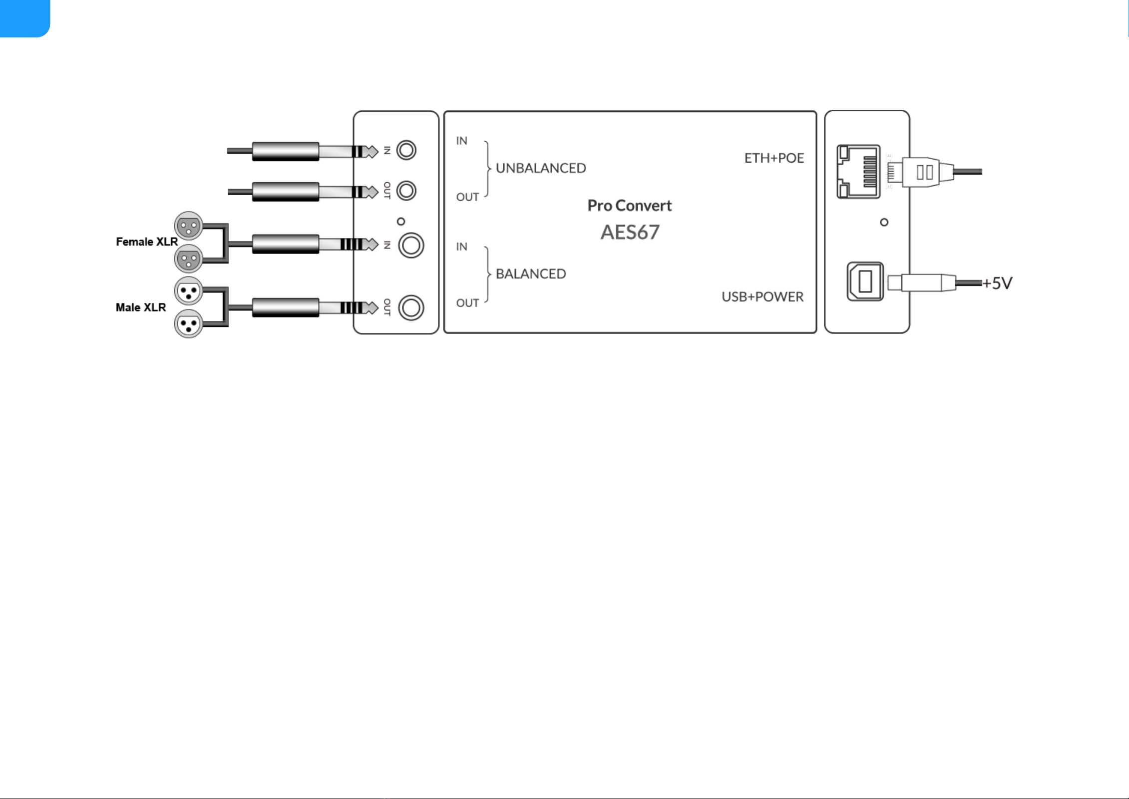
Figure1. Cable connections
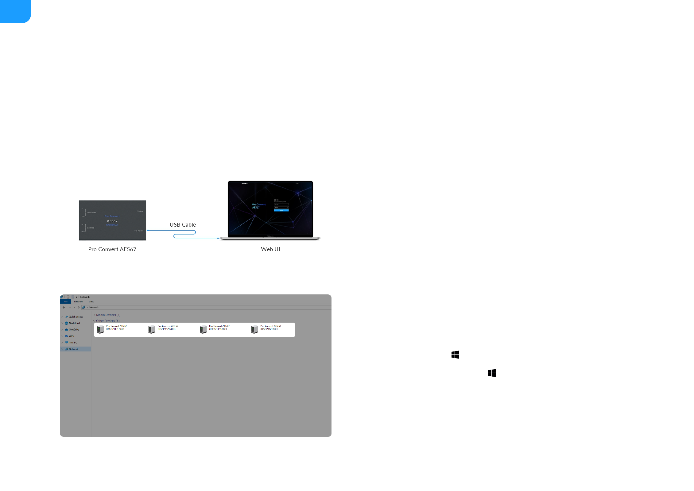
Figure2. Find your Pro Convert device in the Network > Other Devices section
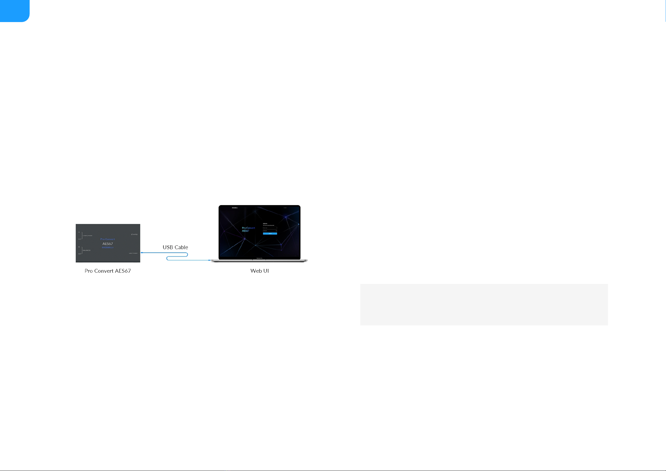
Accessing the Web UI
If you know your device's IP address, type it into your web browser to display
the Web UI. Alternatively, you can access the Web UI in one of the following
ways.
1. For Windows 7/8/8.1/10/11 users, you can find and access your Pro
Convert device as a Network device in a File Explorer window.
2. Using the USB NET function.
Solution 1: using Windows File Explorer
This method is available for Windows(Win7 and above) users.
1. Connect your converter via Ethernet and power it up as shown on the left
Figure1 Cable connections.
2. Open a File Explorer window in one of the following ways.
3. Select the Network at the bottom of the list of items on the left side of the
File Explorer.
4. Turn on the network discovery function if prompted.
Pro Convert allows to be controlled via a web-based user interface. With the Web UI, you can monitor the device’s working status, input signal status, and configure
settings for your sessions.
Click on the Start button and find File Explorer in the Start menu.
■
Press the Windows logo key + E.
■
Select the folder icon on the taskbar.
■