Specifications
Input
Alarms (Up to 2 points) (Optional)
Performance
Control
General specifications
Input
a) Thermocouple : K, J, E, T, R, S, B, N (JIS/IEC), PLII (NBS)
W5Re/W26Re(ASTM), U, L (DIN)
•Input impedance : Approx.1MΩ
•Influence of external resistance : Approx. 0.2µV/Ω
•Input break action : Up-scale
b) RTD : Pt100(JIS/IEC), JPt100(JIS)
•Influence of lead resistance : Approx. 0.01[%/Ω] of reading
•Maximum 10Ωper wire
•Input break action : Up-scale
•Input short action : Down-scale
c) DC voltage input :0 to 5V DC, 1 to 5V DC, 0 to 10V DC
d) DC current input :0 to 20mA DC, 4 to 20mA DC
•For DC current input, connect a 250 Ωresister to the input terminals.
•Refer to the Input and Range and Input CodeTable for details.
•Input break action : Down-scale
•Both heat/cool control outputs are OFF for heat/cool PID action.
•Reading is around zero for 0 to 5V DC input, 0 to 10V DC input and
0 to 20mA DC input.
Sampling time
0.5 sec.
PV bias
- span to +span (Within -1999 to 9999)
Measuring accuracy
a) Thermocouple
±(0.3% of reading + 1 digit) or ±2°C (4°F) whichever is larger
•Accuracy is not guaranteed between 0 and 399°C (0 and 799°F) for
type R, S and B.
•Accuracy is not guaranteed less than -100.0°C (-158.0°F) for type
T and U.
b) RTD
±(0.3% of reading + 1 digit) or ±0.8°C (1.6°F) whichever is larger
c) DC voltage and DC current
±(0.3% of span + 1 digit)
Insulation resistance
More than 20MΩ(500V DC) between measured terminals and ground
More than 20MΩ(500V DC) between power terminals and ground
Dielectric strength
1000V AC for one minute between measured terminals and ground
1500V AC for one minute between power terminals and ground
Control method
a) PID control (with autotuning and self-tuning function)
•Available for reverse and direct action. (Specify when ordering.)
•ON/OFF, P, PI and PD control are also selectable.
ON/OFF action differential gap : 2°C(°F) (Temperature input)
0.2% (Voltage, current input)
b) Heat/cool PID control (with autotuning function)
•A
ir cooling and water cooling type are available.(Specify when ordering.)
Major setting range
Set value : Same as input range.
Heat side proportional band
:
1 to span or 0.1 to span
(ON/OFF action when P=0)
Cool side proportional band :
0 to 1000% of heat side proportional band
Integral time : 0 to 3600sec.(PD action when I=0)
Derivative time : 0 to 3600sec.(PI action when D=0)
Anti-Reset Windup(ARW)
:1 to 100% of heat side proportional band
(Integral action is OFF when ARW=0)
Proportional cycle time : 1 to 100 sec.
Deadband/Overlap : -span to +span (Within -1999 to 9999)
Outputs
Output
Can be set for control or alarm functions.
•Alarm output can be set for energized/de-energized action.
•Alarm output can be set for AND/OR logic calculation.
Number of outputs : 2 points
Output type
Relay contact output :
250V AC 2A (resistive load), Form A contact
Voltage pulse output : 0/12V DC
(Load resistance : more than 600Ω)
•Measurement terminals and output terminal are not isolated.
Alarm type
Deviation High, Deviation Low, Deviation High-Low, Deviation Band
P
rocess High, Process Low, Set value High, Set value Low
Loop break alarm(LBA)
Setting range
a) Deviation alarm :
-
span to +span (Within
-
1999 to 9999)
b) Process alarm : Same as set value (SV).
c) Set value alarm : Same as set value (SV).
d) Loop break alarm : 0.0 to 200.0 min.
Differential gap
2°C (°F) or 2.0°C (°F)
(Temperature input)
, 0.2%
(Voltage, current input)
Communications (Optional)
Waterproof and dustproof (Optional)
Compliance with standards
a)
Communication method
:Based on RS-485 (two-wire)
b)
Communication speed :
2400, 4800, 9600, 19200 BPS
c) Protocol : ANSI X3.28(1976) 2.5 A4
MODBUS
d) Bit format
Start bit : 1
Data bit : 7 or 8 •For MODBUS 8 bit only
Parity bit : Without, Odd or Even
Stop bit : 1 or 2
e) Communication code : ASCII(JIS) 7-bit code
f) Maximum connection : 31 ( Address can be set from 0 to 99.)
Dustproof and waterproof protection : IP66
•Dustproof and waterproof protection are effective only from the front direction
when installed on a panel.
•Dustproof and waterproof are not effective when controllers are closely mounted.
Contact input (Optional)
Number of inputs : 2 points
Contact input type
a) RUN/STOP switching (OPEN :STOP, CLOSE :RUN)
b) STEP function (OPEN : SV1, CLOSE :SV2)
Input rating
Non-voltage contact input.
(OPEN : 500kΩor more, CLOSE : 10Ωor less)
• CE marked
•UL recognized
•CSA certified
•C-Tick marked
Supply voltage
a) 85 to 264V AC (Including supply voltage variation)
[Rating :100 to 240V AC] (50/60Hz common)
b) 21.6 to 26.4V AC(Including supply voltage variation)
[Rating :24V AC] (50/60Hz common)
c) 21.6 to 26.4V DC(Ripple rate 10% p-p or less)
[Rating :24V DC]
Power consumption
Less than 4VA (at 100V AC), 7VA (at 240V AC) for standard AC type
Less than 4VA for 24V AC type
Less than 100mA for 24V DC type
Effect by power failure
A power failure of 20 ms or less will not affect the control action.
If power failure of more than 20 ms occurs, controller will restart.
Operating environments :0 to 50°C [32 to 122°F] , 45 to 85% RH
Memory backup : Backed up by non-volatile memory.
Net weight : Approx. 110g
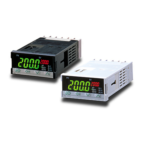
External Dimensions (W x H x D) : 48 x 24 x 100mm (1/32 DIN)
Operating environment
Free from corrosive and flammable gas and dust.
Other conditions
Free from external noise, vibration, shock and exposure to direct sunlight.
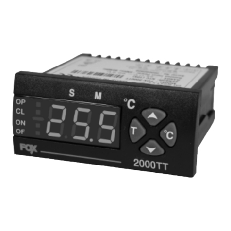
SA200
Digital Temperature
Controller
R
R
3SA200_03E


