PPI HumiTherm Ultra User manual

HumiTherm Ultra User Manual
Temperature + Humidity (%RH)
Control & Recording System
with 8 / 16 Mapping Inputs
User Manual
HumiTherm Ultra
PPI
HumiTherm Ultra
Touch Operation Panel

HumiTherm Ultra User Manual
CONTENTS
1. MOUNTING & ELECTRICAL CONNECTIONS : HMI (TOUCH PANEL) 1
2. MOUNTING & ELECTRICAL CONNECTIONS : microPLC 4
3. MOUNTING, ELECTRICAL CONNECTIONS & JUMPER SETTINGS : MAPPING 7
4. BASIC OPERATION & PARAMETERS ORGANIZATION 11
5. OPERATOR LEVEL PARAMETERS 20
6. SUPERVISORY LEVEL PARAMETERS 22
7. FACTORY LEVEL PARAMETERS 26
APPENDIX-A : DC LINEAR SIGNAL INTERFACE 47
APPENDIX-B : COMPRESSOR SETTING PARAMETERS 50
APPENDIX-C : STANDBY SENSORS 53
APPENDIX-D : STANDBY CONTROL GADGET 55
APPENDIX-E : DOOR LOCK 58
APPENDIX-F : DIGITAL INPUT & OUTPUT 59

1
HumiTherm Ultra User Manual
4.3” Mounting
Dimensions
Overall
Panel Cutout
128(W) X 102(H) X 55(D), mm
121(W) X 95(H), mm
Table 1.1
128 mm
102 mm
Figure 1.1
95 mm
(Panel Cut)
55 mm
5 mm
121 mm
(Panel Cut)
12
3
4.3” Electrical Connections
Section 1
MOUNTING & ELECTRICAL CONNECTIONS : HMI (TOUCH PANEL)
Figure 1.2

2
HumiTherm Ultra User Manual
199 mm
(Panel Cut)
206 mm
136 mm
129 mm
44 mm
6.5 mm
(Panel Cut)
Dimensions
Overall
Panel Cutout
206(W) X 136(H) X 44(D), mm
199(W) X 129(H), mm
7” Mounting
Table 1.2
Figure 1.3

3
HumiTherm Ultra User Manual
7” Electrical Connections
Figure 1.4
1
2
3
3-Pin Male / Female Connector (5.08 mm pitch)
Supply Voltage : 20 to 28 VDC (24 V Nominal)
9 (4.3” HMI) / 15 (7” HMI) Pin D Type Connector
RS485 Serial Communication with microPLC &
Mapping Unit
6 Pin PS/2 Connector
RS232 Serial Communication with PC
24VDC FG
+-
COM2 ETHERNET
COM1 USB
HOST SD-CARD
3
1 2
RESET
PULL
Battery Cover
15 Pin
Table 1.3
9 Pin

4
HumiTherm Ultra User Manual
Mounting (Base / Wall Mounting)
microPLC Electrical Connections
Stby Set Select
525150494847464544
Alarm ACK
1 2 3 4 5 6 7 8 9 10 11 12 13 22 2314 15 16 17 18 19 20 21
Power Fail
Door Open
Thermostat
Thermostat
Water Level
Water Level
Heater
Humidifier
Compressor
Alarm
Main Set Select
Heater
Humidifier
Compressor
Main
RS485
mA
Pt100
V
mA
Pt100
V
Stability Control
mA
V
mA
V
43424140393837363534333231302928
Main
27262524
Door Lock
Standby
Digital Inputs
Digital Outputs
HMI
Temperature
Humidity Temperature
Humidity
microPLC
Stby
Standby
Main
18~32VDC
Supply 5VDC
Exc
+
-
+
-
+
-
+
-
+
-
+
-
+
-
+
-
+
-
+
-
+
-
+
-
+
-
+-
+-
+-
+-
+-
+-
+-
+-
Figure 2.2
Figure 2.1
Section 2
MOUNTING & ELECTRICAL CONNECTIONS : microPLC
179mm
100mm
8mm
8mm
ø5mm Mounting Hole
ø5mm Mounting Hole
77mm

5
HumiTherm Ultra User Manual
DESCRIPTIONS
The connections are described as under:
0/4~20mA
78 9
mA
Figure 2.3 (b)
0/1~5V, 0~10V
7 8 9
V
Figure 2.3 (a)
Humidity Transmitter with DC Voltage (V) Output
The Figures 2.3(a) depicts wiring connections for voltage output transmitter. The Excitation Voltage
can be obtained from an external source or from the controller (5 VDC).
Humidity Transmitter with DC Current (mA) Output
The Figures 2.3(b) depict wiring connections for current output transmitter. Note that terminals 8 & 9
should be shorted. The Excitation Voltage can be obtained from an external source or from the
controller (5 VDC).
Main Humidity (%RH) Transmitter Input (Terminals : 7,8, 9)
The Controller accepts DC Current (mA) / DC Voltage (V) as Humidity input. The connections are
described below.
Figure 2.4 (a) Figure 2.4 (b) Figure 2.4 (c)
Main Temperature (°C) Sensor / Transmitter Input (Terminals : 10, 11, 12, 13 )
The Controller accepts RTD Pt100 (3-wire / 2-wire) or DC Current (mA) / DC Voltage (V) as Temperature input. The
connections are described.
0/1~5V, 0~10V
V
10 11 12 13
RTD Pt100
10 11 12 13
0/4~20mA
mA
10 11 12 13
RTD Pt100, 3-wire
Connect single leaded end of RTD bulb to terminal 10 and the double leaded ends to terminals 11 & 12 as shown in Figure
2.4(a). Use copper conductor leads of very low resistance ensuring that all 3 leads are of the same gauge and length. Avoid
joints in the cable.
Temperature Transmitter with DC Voltage (V) Output
The Figures 2.4(b) depicts wiring connections for voltage output transmitter. The Excitation Voltage can be obtained from an
external source or from the controller (5 VDC).
Temperature Transmitter with DC Current (mA) Output
The Figures 2.4(c) depict wiring connections for current output transmitter. Note that terminals 12 & 13 should be shorted. The
Excitation Voltage can be obtained from an external source or from the controller (5 VDC).
5 VDC Excitation Voltage (Terminals : 4, 5)
The Controller is supplied with inbuilt 5VDC Excitation Voltage as standard. The Excitation Voltage can be used to power
external Temperature and/or RH Transmitters.
The ‘+’ and ‘-’ terminals are for voltage ‘Source’ and ‘Return’ paths, respectively.

6
HumiTherm Ultra User Manual
2 Pole
Isolating Switch
Fuse
1
DC Power
Source
+
-
+
2-
Mains
Earth 3
Figure 2.5
[Optional] Standby Humidity (%RH) Transmitter Input (Terminals : 14, 15, 16, 17)
[Optional] Standby Temperature (°C) Sensor / Transmitter Input (Terminals : 18, 19, 20, 21)
The Control Unit optionally supports Inputs for Standby (redundant) Humidity & Temperature sensor / transmitter. The
Connection detail are the same as for main sensor / transmitter described above.
[Optional] Door Output (terminals : 24, 25)
[Optional] Standby Set Select Output (terminals : 26, 27)
[Optional] Main Set Select Output (terminals : 28, 29)
[Optional] Standby Compressor Output (terminals : 30, 31)
[Optional] Standby Humidifier Output (terminals : 32, 33)
[Optional] Standby Heater Output (terminals : 34, 35)
Main Compressor Output (terminals : 36, 37)
Main Humidifier Output (terminals : 38, 39)
Main Heater Output (terminals : 40, 41)
Alarm Output (terminals : 42, 43)
All the above control & alarm outputs are Voltage pulses (12VDC @ 40mA) for driving external SSR or Relay. The ‘+’ and ‘-’
terminals are for voltage ‘Source’ and ‘Return’ paths, respectively.
The Optional Outputs are fitted only if Controller is ordered with Standby Control Outputs.
[Optional] Standby Thermostat Digital Input (Terminals 44, )46
[Optional] Standby Water Level Digital Input (Terminals 45, )46
Main Thermostat Digital Input (Terminals 47, )46
Main Water Level Digital Input (Terminals 48, )46
Alarm Acknowledge Digital Input (Terminals 50, )49
Power Fail Digital Input (Terminals 51, )49
Door Open Digital Input (Terminals 52, )49
(Terminals 46 & 49 are Common)
Potential-free contact closure input terminals are provided as digital inputs. An ‘Open’ or ‘Close’ switch position is detected as
input.
For reliable noise free communication, use a pair of twisted wires inside screened cable. The wire should have less than 100
ohms / km nominal DC resistance (Typically 24 AWG or thicker). Connect the terminating resistor (Typically 100 to 150 ohm)
at one end to improve noise immunity.
HMI (Terminals 22, 23) COMMUNICATION PORT
POWER SUPPLY 1(Terminals , 2, 3)
As standard, the is supplied with power connections suited Module
for to V C . The accuracy / p formance of the 18 32 D power source er
Module is not affected by the variations in the supply within sp cified e
limits of to 3 VDC. Use well-insulated copper conductor wire of 18 2
the size not smaller than 0.5mm² for power supply connections
ensuring proper polarity as shown in Figure . The is not 2.5 Module
provided with fuse and power switch. If necessary, mount them
separately. Use a blow fuse rated for 0.5A current. slow
For safety and enhanced electrical noise immunity, it is highly recommended to connect Main Power Supply ‘Earth’
to terminal 3.

7
HumiTherm Ultra User Manual
Section 3
MOUNTING, ELECTRICAL CONNECTIONS & JUMPER SETTINGS : MAPPING
Figure 3.2
Mounting (Base / Wall Mounting)
Mapping Electrical Connections
Figure 3.1
210mm
110mm
ø5mm Mounting Hole
ø5mm
Mounting Hole
8mm
5mm
205mm
88mm
SUPPLY
COMM PORT
B BB B
52 53 54 55
1 2 346 7 8 9 10 11 12 13 14 15 16 17 18 19 20 21 22 23 24
5
mV / V
mA
%RH
MAP 1
°C %RH
MAP 2
°C %RH
MAP 3
°C %RH
MAP 4
°C %RH
28293031323334353637383940
4142
43
44
45
46
47
48495051
MAP 8
%RH °C
MAP 7
%RH °C
MAP 6
%RH °C
MAP 5
%RH °C
UniMap
4 / 8 Points
Mapping Module
25
84 ~ 264
VAC
26 27
LN
Sr. No.:
PPI
°C
RTD
mV / V
mA
A1 A2 A3 B1 B2 B3
B1B2
B3 A1A2
A3
B1 B2 B3
A1 A2 A3
B1 B2 B3 A1 A2 A3 B1 B2 B3 A1 A2 A3 B1 B2 B3 A1 A2 A3
A1A2
A3 B1B2
B3 A1A2
A3 B1B2
B3 A1A2
A3 B1B2
B3

8
HumiTherm Ultra User Manual
Map Inputs
Each of the °C and %RH inputs are identical from wiring connection viewpoint. The descriptions below apply to all the inputs
with no deviations.
Make sure that proper jumper settings are made for each input for the selected input type as described later in this ection.s
RTD Pt100, 3-wire
Connect single leaded end of bulb to and the double leaded ends to terminals and (interchangeable) as shown RTD A1 A2 A3
in Use copper conductor leads of very low resistance ensuring that all 3 leads are of the same gauge and length. Figure 3.3(a).
Avoid joints in the cable.
DC Linear Voltage (mV / V) & Current (mA)
Use a shielded twisted pair with the shield grounded at the signal source for connecting mA / mV / V source. Connect common
(-) to and the signal (+) to , as shown in A2 / B2 A1 / B1 Figure 3.3(a) & (b).
POWER SUPPLY
Figure 3.4
As standard, the controller is supplied with power connections suited for 8 to 264 VAC line supply. Use well-insulated copper 5
conductor wire of the size not smaller than 0.5mm² for power supply connections. Connect Line (Phase) supply line to terminal
26 and the Neutral (Return) supply line to terminal 27 as shown in Figure . . The controller is not provided with fuse and 3 4
power switch. If necessary, mount them separately. Use a time lag fuse rated 1A @ 240 VAC.
Line
Neutral
26 (L)
27 (N)
2 Pole
Isolating Switch
Fuse
Power Supply
Terminal
Figure 3.3(b)Figure 3.3(a)
RTD
A1 A2 A3
°C
mV / V / mA
A1 A2 A3
%RH
mV / V / mA
B1 B2 B3

9
HumiTherm Ultra User Manual
SERIAL COMMUNICATION PORT
Figure 3.5
The wiring connections for interfacing the HMI with mapping unit is shown in the figure 3.5.
Mapping
HMI
RS485 Port
OUT
IN
RS485
Port
To microPLC
INPUT TYPE : JUMPER SETTINGS
The Mapping Unit (UniMap) is supplied with 8 ( ) or 16 ( T + 8RH) s. Each can be user configured for a 4T + 4RH 8 Map Input Input
variety of input types which requires appropriate parameters settings and jumper settings on . The figure shows UniMap 3.6
the locations of jumper setting arrangements for each . input
Figure 3.6
3
2
1
4
1
2
34
°C
MAP 1
%RH
MAP 4
°C
MAP 5
%RH
MAP 8

10
HumiTherm Ultra User Manual
The jumper setting arrangement comprises of as shown in the figure below. The figure also depicts Pins & Shorting-Link 3.7
how to mount the Shorting-Link for a particular jumper setting.
Shorting Link
Placed
Shorting Link
Parked
Pins Shorting
Link
Figure 3.7
The figures below show the jumper settings for different input types.
321
4
Place Shorting
Link on Pins 1 & 2
RTD Pt100 (3-wire)
321
4
Place Shorting
Link on Pins 2 & 3
0-20mA, 4-20mA
321
4
Park Shorting Link
0-50mV, 0-200mV, 0-1.25V,
0-5V, 1-5V, 0-10V

11
HumiTherm Ultra User Manual
BASIC OPERATION & PARAMETER ORGANIZATION
Section 4
ALARM INDICATOR
This icon appears if one or more process alarms are active. The Alarm Relay gets activated whenever any alarm becomes
active. The user can acknowledge the alarm (de-activate the relay) by touching this icon.
BATTERY INDICATOR
This icon appears if the Mains power has failed and the controller is currently powered through an auxiliary power source like
Battery or Inverter.
COMM ERROR INDICATOR
This icon appears if the HMI communication link with the Control Unit, Mapping Unit or GSM Module is broken. Upon touching
this icon a message window pops up showing which communication link(s) is broken.
CALENDER DATE & CLOCK TIME
These two fields show the current date (DD/MM/YY) & time (HH:MM:SS, 24 Hours format), respectively.
TEMPERATURE VALUE & %RH VALUE
These two fields show the Temperature & %RH Process Values in 0.1 °C / %RH resolution. In case of errors the field shows
OPEN (Sensor Open), OVER (Process Value above Max Range), UNDR (Process Value below Min Range). The Process
Values are shown in Black color under normal condition. The Error Messages are shown in Red color.
TEMPERATURE SETPOINT & %RH SETPOINT
These two fields show the Temperature & %RH Set Values (SP) in 0.1 °C / %RH resolution. If enabled, these values can be
edited by touching the respective field. Upon touching a Numeric Keypad pops up for setting.
TUNE STATUS INDICATOR
This text appears if the controller is self tuning the temperature and / or %RH control loop.
STATUS VIEW BUTTON
This a touch button that enables navigation through various process status screens. The Screens are shown below.
Clock Time
Calendar Date
Alarm Indicator
%RH Value
Temperature Value
%RH Setpoint
(Optional Touch Button)
Set-up Mode Button
Temperature Setpoint
(Optional Touch Button)
Status View Button
Map View Button Door Open Button
Battery Indicator
Tune Status Indicator
Comm Error Indicator
Tuning
Upon Power up to the HMI, after a few initialization screens, the Main (Home) screen is displayed. This is the screen that shall
be used most often and is described below in details.

12
HumiTherm Ultra User Manual
Process Status Screen
This screen shows various rocess Alarm status and the information regarding working / fa ure of p il various Main and Standby
Sensors (Temperature & %RH) & Control Gadgets (Air Heater, Boiler Heater & Compressor). The contents on this screen are
dependent on whether Standby Sensors and / or Standby Control Gadgets are installed or not. Accordingly the following four
variants of this screen exist:
1. Alarm Only
2. Alarm + Standby Sensor
3. Alarm + Standby Control
4. Alarm + Standby Sensor + Standby Control
Alarm + Standby Sensor + Standby Control
Alarm + Standby Control
Alarm + Standby Sensor
Touch Button to go to
Next Screen
Touch Button to
Acknowledge Alarm
Touch Button to go to
Home (Main) Screen
Touch Button to go to
Previous Screen
Alarm Only

13
HumiTherm Ultra User Manual
Record Status
Th rage capacity, numbers of current stored records and available free space.is screen shows the total record sto
Output Status
This screen shows :
wHeating & Humidification % output power
wOn-Off Status for Main & Standby (if installed) Air Heater, Boiler Heater (Humidifier) & Compressor
wAlarm Relay Status
5000
1
4999
SMS Status
This screen shows the status related to GSM Module (if installed).

14
HumiTherm Ultra User Manual
MAP VIEW BUTTON
This is a touch button that opens up screen(s) to view process values for mapping s. The installed mapping s could input input
be 8 (4 Map Points : 4T + 4RH) or 16 (8 8T + 8RH) and accordingly 1 or 2 screens displayed. Note that this Map Points : are
touch button is not available if no mapping inputs are installed. The Screens are shown below.
Appears for both 8 & 16 Map Inputs Appears for 16 Map Inputs only
25.0
59.6
24.7
60.2
25.2
60.8
25.3
60.1
22.0
57.5
24.8
61.2
25.1
60.8
27.2
62.3
DOOR OPEN BUTTON
If the Humidity cabinet is equipped with Door Lock, this touch button opens a screen that allows password entry for unlocking
the cabinet door by authorised person. Also the authorised person’s identity is logged for audit purpose.
Access Level Default Password
Operator 0000
Supervisory 0001
Factory 0002
SET-UP MODE BUTTON
This touch button opens a screen that allows access to Operator, Supervisory or Factory Level parameter settings through
appropriate password entry. 4 character
The Factory default passwords are as below :

15
HumiTherm Ultra User Manual
Upon touching one of the levels, a keyboard for password entry pops-up as shown below.
Text Screen
The user must touch the text screen to make it
editable. Upon touch the text screen shows a blue
band as shown below.
****
Non Editable
Editable after touch
Password entry on
editable text Screen
****
While the screen is editable, type 4 character password & then press ENTER Key. If the password is correct, the parameter
setting screen opens up. Use ESC key (in case password is not known) to pop down the key pad.
Once an access level is entered, the user can change the password for that level as shown below as an example for operator
level.
0005
25.0
2.0
2.0
60.0
2.0
2.0

16
HumiTherm Ultra User Manual
Each access level may have sub levels for convenient parameter grouping. The Table . lists various parameters with levels 4 1
and sub levels.
Sub-Level Parameters
Level
Operator
Supervisory
Recording
Clock & Calendar
Door Lock Access
Maintenance
Standby Switching
Temperature
Set Value
Low Deviation Alarm
High Deviation Alarm
%RH
Set Value
Low Deviation Alarm
High Deviation Alarm
SP Edit on Home Screen
Recording Interval
‘Delete Record’ Command
Calendar Date (DD/MM/YY)
Clock Time (HH:MM:SS)
Lock Position (On / Off)
Password Entry
Repair Acknowledge ‘Control Gadget’
Repair Acknowledge ‘Input Sensor’
‘Switch Main / Standby Outputs’
‘Switch to Standby Sensors’
Table 4.1
GSM Machine ID
Reset GSM Module
SMS Alert
SMS
Temperature
Control Settings
Alarm Settings
Input Settings
Control Settings
Alarm Settings
Input Settings
%RH
Input Type,
Signal Range Low, Signal Range High,
Display Range Low, Display Range High,
Zero Offset
Inhibit (Yes / No),
Low Alarm Deviation, High Alarm Deviation,
Hysteresis
Heat Zone PID Constants,
Cool Zone PID Constants,
Output Cycle Time (Sec.),
Control SP
Setpoint Low Limit, Setpoint High Limit
Self Tune
Input Type,
Signal Range Low, Signal Range High,
Display Range Low, Display Range High,
Zero Offset
Inhibit (Yes / No),
Low Alarm Deviation, High Alarm Deviation,
Hysteresis
Factory
Heat Zone PID Constants,
Cool Zone PID Constants,
Output Cycle Time (Sec.),
Control SP
Setpoint Low Limit, Setpoint High Limit
Self Tune

17
HumiTherm Ultra User Manual
Sub-Level Parameters
Level
Factory
Compressor
Water Level
Door Open
Power Fail
Mode (ON, OFF, PV Based, SP Based),
Boundary SP or Compressor SP,
Time Delay, Hysteresis
Zone Select (Single, Dual)
Detection Enable (Yes / No),
Door Open Logic (Open / Close),
Alarm Delay (Sec.)
Detection Enable (Yes / No),
Power Fail Logic (Open / Close)
Float
Detection Enable (Yes / No),
Low Level Logic (Open / Close)
Thermostat
Detection Enable (Yes / No),
Low Level Logic (Open / Close)
Common Boiler (Yes / No)
Control Gadgets
Standby
Sensor Inputs
Sensor Fail Detection Limits
Fail Detect Time (Min)
Cyclic Time (Hrs.)
Inhibit Time (Hrs.)
Mapping
Configuration
Temperature
%RH
Select Mapping Inputs (4T + 4RH, 8T + 8RH)
Alarm Settings
Input Settings
Low Alarm (Common for all Inputs)
Set Value, Hysteresis, Inhibit
High Alarm (Common for all Inputs)
Set Value, Hysteresis, Inhibit
Input Type,
Range Low, Range High,
Zero Offset
Alarm Settings
Input Settings
Low Alarm (Common for all Inputs)
Set Value, Hysteresis, Inhibit
High Alarm (Common for all Inputs)
Set Value, Hysteresis, Inhibit
Input Type,
Range Low, Range High,
Zero Offset

18
HumiTherm Ultra User Manual
PARAMETER SETTINGS
There are 3 types of parameters; Numeric, String Option and Commands. The setting methods for different types are
described below.
Numeric Parameters
This type of parameter has 2 fields; & as shown in the figure. The value for this type of parameter is set Name Field Value Field
using a Numeric keypad that pops up upon touching the for the parameter. The value can be edited using numeric Value Field
keys & other functional keys as shown in the figure. Use ENT key for storing the new value or use ESC key to revert without
changes. Touching ENT or ESC key, the keypad automatically collapses.
Name Field Value Field
Note that if the modified value falls outside the Minimum or Maximum limits specified for the
parameter value then the parameter retains the old value.
Selected Option
Unselected Options
String Option Parameters
This type of parameter has 2 or more fixed options to choose from. All the options are shown in rectangular boxes with
appropriate texts as shown in the figure. Only one of the several options can be selected. The selected option box is shown in
bright ( ) color, while all other unselected options are shown in dark ( ) color. For selecting the desired option. just touch
the box and wait for a while until the color changes from unselected to selected.
Table of contents
Other PPI Temperature Controllers manuals
Popular Temperature Controllers manuals by other brands

Middleby Marshall
Middleby Marshall 37626 Installation, programming and troubleshooting instructions
THORLABS
THORLABS MTD415T datasheet
NPI
NPI TC-10 operating instructions
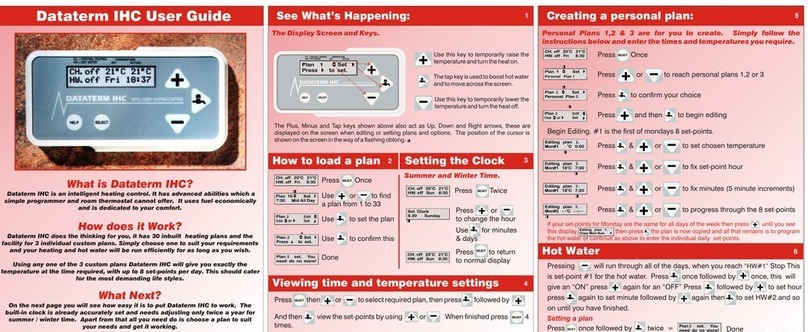
Warmworld
Warmworld Dataterm IHC user guide
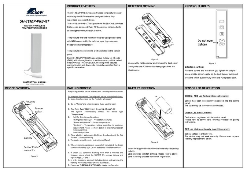
Crow
Crow SH-TEMP-PRB-XT instruction manual
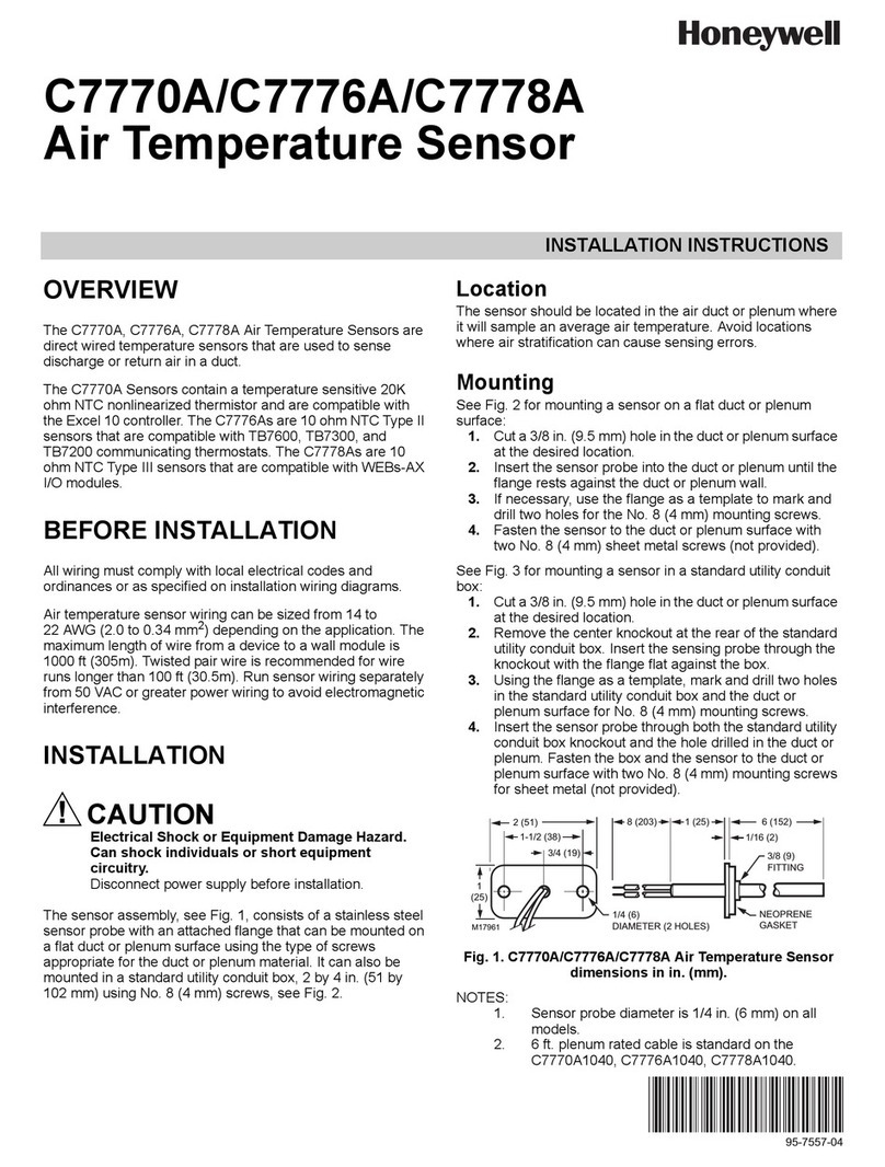
Honeywell
Honeywell C7776A installation instructions
