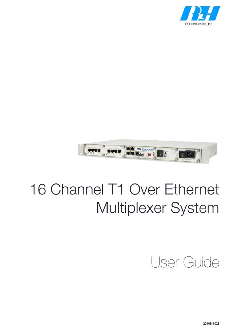
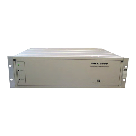
RLH Industries iMux User manual

iMux Fiber Optic
Multiplexer System
User Guide
U-050 02014A-0911
RLH Industries, Inc.

RLH Industries, Inc.
Copyright © 2013 RLH Industries, Inc. All rights reserved.
No part of this document may be copied or distributed without
permission.
The RLH logo may not be used for commercial purposes without the
prior written consent of RLH and may constitute trademark infringement.
Other company and product names mentioned herein are trademarks of
their respective companies. Mention of third-party products is for
informational purposes only and constitutes neither an endorsement nor
a recommendation. RLH assumes no responsibility with regard to the
performance or use of these products.
The information contained in this document is the property of RLH
Industries, Inc. and may not be reproduced or disseminated to third
parties without the express written permission of RLH.
Every effort has been made to ensure that the information in this manual
is accurate. RLH is not responsible for printing or clerical errors. Because
we are constantly seeking ways to improve our products, specifications
and information contained in this document are subject to change
without notice.
RLH Industries, Inc.
936 North Main Street
Orange,CA 92867
Ph. 714 532-1672
email: info@fiberopticlink.com
www.fiberopticlink.com
!
2!

Contents
1."Important Information
Intended Audience!8
Conventions!8
General Safety Practices!8
2."Introduction
Product Description!9
Standard Features!9
Application Diagrams!10
Front Panel!11
Front Panel LEDs#11
Module Status LEDs#12
LAN/MGMT Port LEDs#12
Optical Module LEDs #12
Rear Panel!13
4 Channel E1 Module!13
4 Channel T1 Module!13
4 Channel RS-232 Module!14
4 Channel V.35 Module!14
4 Channel Analog Phone (POTS) Modules!15
4 Channel 2/4 Wire Analog Data/Audio/SCADA Module!16
4 Channel 2/4 Wire Analog Data/Audio/SCADA/E&M Module!16
Setting E&M Jumpers and Switches!17
Acronyms!19
3."Before Installing
Observe Special Handling Requirements!20
Be careful when handling electronic components#20
Guidelines for handling terminated fiber cable#20
Prepare for Installation!21
Check for shipping damage#21
Verify system contents #21
Verify matching optical module and fiber modes#21
Contents!3

Site Requirements!21
Site selection#21
Typical application environments #22
Required power sources#22
Test Equipment!22
For T1 service#22
For analog phone service (POTS)#22
For RS-232 service#22
4."Quick Start
Easy Installation!23
Before starting#23
Install the iMux#23
Connect power#23
Connect fiber cables #23
Connect ethernet cables #24
Connect data/phone equipment#24
Start the system#24
5."Configuring the System
Management Interface!25
Using the VT-100 port#25
Select a Startup Profile#25
Main Menu!28
System Configuration!29
System Information Configuration!30
Device Networking Configuration!31
Setting the device IP#31
User Account Management!32
Setting System Access Groups#32
SNMP Agent Configuration!33
Setting the Trap IP#34
Software Upgrade Configuration!34
Remote Server#34
Local File#35
Software Upgrade and Reboot Operation!36
Upgrade Status#36
Upgrade Error Messages #37
Software Reboot Status#37
Network Time Synchronization!39
4!Contents

Scheduling Job Management!40
Networking Service Management!41
Network TroubleShooting Operation!42
LCD Login Configuration!44
Event Management!45
Event Class Processing Configuration#46
Event Alarm Processing Configuration#47
System Profile Management!48
Configuration File Management!50
Terminal File Transfer Operation!54
Tributary Slot Interface Selection!55
E1 Interface Configuration#56
V.35 Interface Configuration#58
FXO/FXS Interface Configuration#60
T1 Interface Configuration#61
Tributary TSA configuration#62
Normal mode (All E1 channels)#63
Seven E1 channels and one V.35 channel mode#64
Four E1 channels and one V.35 channel mode#65
Eight E1 channels and one V.35 channel mode#66
Optical Interface Parameters Configuration!67
Trunk Ethernet Configuration Selection!69
Trunk Ethernet General Parameter Config#70
Trunk Ethernet Parameters Config#71
Trunk Ethernet Port Rate Configuration#72
Trunk Ethernet Port VLAN Config#73
Trunk Ethernet VLAN Table Config Management#74
Trunk Ethernet QoS Port Config#75
Trunk Ethernet QoS Schedule Config#76
Trunk Ethernet QoS Tag Priority Config#77
Trunk Ethernet Tag Mark/Remark Config#77
Data Port Parameters Configuration!78
Performance Management Threshold Configuration!79
PM Threshold Configuration#79
Dsx1 Interface Threshold Setting#80
Aggregate Interface Threshold Setting#82
Fault Management Parameters Configuration!83
Fault Parameter Configuration#83
Alarm Severity Config#84
Power Failure Monitoring Parameter Config#85
Contents!5

External Clock Configuration and Monitoring!86
External Clock Configuration#86
External Clock Monitoring#87
OE Protection Switching!88
Automatic laser shutdown#89
Equipment Status Monitoring!90
Status Monitoring Screen#90
Local site tributary card setting#91
Remote site tributary card setting:#92
Performance Monitoring!93
Aggregate/Dsx1 Performance Monitoring#93
Performance Monitoring Settings#94
Trunk Ethernet Performance Monitoring#95
Path Alarm/State Monitoring!96
Interface Alarms #96
Loopback/V.54 Testing!97
E1 Module#97
V.35 Module#98
PRBS Test!100
One way PRBS test step#101
Event Browsing!103
6."Front Panel Operation
Front LCD controls!104
LCD Menu Tree!105
7."Web Operating Interface
Using the web interface!109
Saving or loading profiles!111
8."Telnet Operating Interface
SNMP management!112
9."Appendix
Craft & External Alarm Ports Pin Assignment!113
External clock port#113
Craft port (VT100)#113
Alarm port#113
External alarm port#114
6!Contents

10."Troubleshooting
First Step: Isolate the problem!114
Common Issues!114
Power supply issues!115
AC power#115
Verifying fiber cable!115
Module installation!115
Troubleshooting Guide!116
11."Specifications
General Specifications!118
Optical Module Specifications!118
Service Module Specifications!119
12."Ordering Information
Base Systems!120
Port Modules!120
Optical Modules!121
13."Support
Technical Support!122
Contact Information!122
Contents!7

1."Important Information
Intended Audience
This manual is intended for use by knowledgeable telco/network installation, operation and repair personnel.
Every effort has been made to ensure the accuracy of the information in this manual is accurate. However, due to
constant product improvement, specifications and information contained in this document are subject to change
without notice. Please refer to the iMux User Guide for additional information.
Conventions
Symbols for notes, attention, and caution are used throughout this manual to provide readers with additional
information, advice when special attention is needed, and caution to prevent injury or equipment damage.
Notes: Helpful information to assist in installation or operation.
Attention: information essential to installation or operation.
Caution: Important information that may result in equipment damage or injury if ignored.
General Safety Practices
The equipment discussed in this manual may require tools designed for the purpose being described. RLH
recommends that installation and service personnel be familiar with the correct handling and use of any
equipment used, and follow all safety precautions including the use of protective personal equipment as required.
Caution - Severe Shock Hazard
• Never install during a lightning storm or where unsafe high voltages are present.
• Active T1 lines carry high DC voltages up to 56V. Use caution when handling T1 wiring.
Laser Safety
• Radiation emitted by laser devices is dangerous to to human eyes.
• Avoid eye exposure to direct or indirect radiation.
• Do not operate without fiber cable attached or dust caps installed.
8!Important Information

2."Introduction
Product Description
The iMux is a powerful fiber optic modular multiplexer capable of providing up to 16 channels of T1, RS232, 2/4
wire data and analog phone FXO/FXS services, plus four built-in 10/100M Ethernet ports, over a single fiber.
These services are supplied by the modules, up to four, that each offer four lines of communication and may be
installed in any combination. Spares or add-on modules may be ordered separately and are field installable. The
optical modules are available in both dual fiber and single bi-directional fiber (WDM), and up to 2 optical modules
may be installed, providing 1+1 hot-swappable optical protection and making the best use of fiber availability.
The iMux may be managed through SNMP, web Interface, craft port or LCD/menu keys on the front panel. It also
has an external alarm port for alarm input monitoring, as well as 4 programmable alarm contacts. The system
provides local/remote loopback functions that are ideal for network testing and maintenance. The iMux takes up
1RU and comes complete with EIA19” and 23” rack ears, or it may be used on a desktop or shelf.
Standard Features
• Multiplexes up to 16 voice and data channels plus Ethernet over a single fiber
• Up to 4 modules (each with 4 lines) may be used in any combination to mix and match services
• Convenient front LED status indicators
• T1, RS232, POTS, & 2/4 wire Data service modules
• 4 built-in 10/100 Ethernet ports
• Aggregated Ethernet throughput up to 100Mbps
• Optical module auto laser shutdown (ALS), hot swappable 1+1 protection
• Alarm relay has major and minor alarms (audible and visible alarm output)
• Supports SNMP , HTTP / FTP / TFTP remote software upgradeable
• Supports TELNET function to configure and monitor local and remote devices through TCP/IP network
• Available with ringdown circuit operation
• Redundant 48VDC or AC/DC powering options
9!RLH Industries, Inc. • 866-DO-FIBER • www.fiberopticlink.com!Introduction

Application Diagrams
T1
T1
2/4 Wire
Data
RS-232 RS-232
Ethernet
(VLAN/QoS)
Ethernet
(VLAN/QoS)
2/4 Wire
Data
POTS
(FXS)
POTS
(FXO)
RLH iMux RLH iMux
LAN1 LAN2 LAN3 LAN4 MGMT
MAJ
MAJ
MAJ
MAJ
MAJ
MAJ
MAJ
MAJ
1 1 1 1
1
1
1
1
PORTS
LOS/LOF/AIS
E1/V35
CRAFT RST
OE1 OE2
TX RX
WK
L
OS
LSR
ON
TX RX
WK
L
OS
LSR
ON
LAN1 LAN2 LAN3 LAN4 MGMT
MAJ
MAJ
MAJ
MAJ
MAJ
MAJ
MAJ
MAJ
1 1 1 1
1
1
1
1
PORTS
LOS/LOF/AIS
E1/V35
CRAFT RST
OE1 OE2
TX RX
WK
LOS
LSR
ON
TX RX
WK
LOS
LSR
ON
Fiber Optic Cable
Up to 74 mi. / 120km
Multiple Service Example
Ethernet
(VLAN/QoS)
POTS (FXS)
up to 16 POTS Lines
POTS (FXO)
up to 16 POTS Lines
Ethernet
(VLAN/QoS)
RLH iMux RLH iMux
LAN1 LAN2 LAN3 LAN4 MGMT
MAJ
MAJ
MAJ
MAJ
MAJ
MAJ
MAJ
MAJ
1 1 1 1
1
1
1
1
PORTS
LOS/LOF/AIS
E1/V35
CRAFT RST
OE1 OE2
TX RX
WK
L
OS
LSR
ON TX RX
WK
L
OS
LSR
ON
LAN1 LAN2 LAN3 LAN4 MGMT
MAJ
MAJ
MAJ
MAJ
MAJ
MAJ
MAJ
MAJ
1 1 1 1
1
1
1
1
PORTS
LOS/LOF/AIS
E1/V35
CRAFT RST
OE1 OE2
TX RX
WK
LOS
LSR
ON
TX RX
WK
LOS
LSR
ON
Up to 74 mi. / 120km
16 Channels of POTS Example
Fiber Optic Cable
Up to 74 mi. / 120km
RLH iMux RLH iMux
LAN1 LAN2 LAN3 LAN4 MGMT
MAJ
MAJ
MAJ
MAJ
MAJ
MAJ
MAJ
MAJ
1 1 1 1
1
1
1
1
PORTS
LOS/LOF/AIS
E1/V35
CRAFT RST
OE1 OE2
TX RX
WK
L
OS
LSR
ON
TX RX
WK
L
OS
LSR
ON
LAN1 LAN2 LAN3 LAN4 MGMT
MAJ
MAJ
MAJ
MAJ
MAJ
MAJ
MAJ
MAJ
1 1 1 1
1
1
1
1
PORTS
LOS/LOF/AIS
E1/V35
CRAFT RST
OE1 OE2
TX RX
WK
L
OS
LSR
ON TX RX
WK
LOS
LSR
ON
T1
Up to 16 Lines
T1
Up to 16 Lines
Ethernet
(VLAN/QoS)
Ethernet
(VLAN/QoS)
16 Channels of T1 Example
10!RLH Industries, Inc. • 866-DO-FIBER • www.fiberopticlink.com!Introduction

Front Panel
RST
MAJ
MIN
LB
K
RDI
PWR
LCK
ACO
LOS/LOF/AIS
123 4
1
2
3
4
E1/V35 EXTCLK
CRAFT
SL-2100
TX RX
WK
LOS
LSR
ON TX RX
WK
LOS
LSR
ON
LAN1 LAN2 LAN3 LAN4 MGMT
Front Panel LEDs
LED
Color
Name
ON condition
OFF condition
MAJ
RED
Major Alarm
Major alarm event is present and
being signaled through rear panel
alarm connector.
Normal operation
MIN
YEL
Minor Alarm
Minor alarm event is present and
being signaled through rear panel
alarm connector.
Normal operation
LBK
YEL
Loopback
E1 loopback signal received
Normal operation
RDI
YEL
Remote Defect
Indication
Indicates a failure in the remote
terminal.
Normal operation
PWR
GRN
Power
iMux is powered and ON
iMux is powered OFF, or no
power is present
LCK
YEL
Optical Link Lock
The optical link is locked because it
has switched to protect line mode.
Normal operation
ACO
YEL
Alarm Cut Off
Normal operation
ACO Button has been
pressed. See note below.
Note:#ACO Button and LED operation.
The ACO button mutes the audible alarm when a problem occurs. When the button is
pressed the ACO LED illuminates. If any newer alarm is reposted after the ACP button has
been pressed, the external alarm will activate again
Introduction#RLH Industries, Inc. • 866-DO-FIBER • www.fiberopticlink.com!11

Module Status LEDs
RST
MAJ
MIN
LBK
RDI
PWR
LCK
ACO
ACO LOS/LOF/AIS
1 2 3 4
1
2
3
4
E1/V35
PORTS
CRAFT
TX RX
WK
LOS
LSR TX RX
WK
LOS
LSR
LAN1 LAN2 LAN3 LAN4 MGMT
IMux slot number
Port number on
each module
LED
Name
Color
Condition
PORT
Installed port slot
RED
No module is installed at this port number
PORT
Installed port slot
GRN
A module is installed at this port number
E1/V35
Module port status for
any installed module
RED
No connection is detected to that port
E1/V35
Module port status for
any installed module
GRN
Active connection is attached to that module port
Note:"Although the port status LEDs are labeled E1/V35, they will display the status of any module
installed except the analog phone (POTS) modules. The phone module does not display
connections made to each port on the module and the LEDs for those modules only will be
GRN when off-hook and RED when ringing.
LAN/MGMT Port LEDs
LED
Name
Color
ON condition
OFF condition
LAN 1 ~ LAN 4
LAN port activity
YEL
Data is being received
No data is being received
LAN 1 ~ LAN 4
LAN port activity
GRN
Data is being sent
No data is being sent
MGMT
SNMP management
port activity
YEL
Data is being received
No data is being received
MGMT
SNMP management
port activity
GRN
Data is being sent
No data is being sent
Optical Module LEDs
LED
Name
Color
ON condition
OFF condition
LSR
Laser
YEL
Laser condition is OK
Laser not operating
WK
Working
GRN
Activity over fiber
No activity over fiber
LOS
Loss of Signal
RED
Loss of fiber signal
Normal operation
12!RLH Industries, Inc. • 866-DO-FIBER • www.fiberopticlink.com!Introduction

Rear Panel
Any of the modules may be plugged into any position, called a Tributary Slot. These are referred to as TB1~TB4.
Refer to the Specifications section for additional information.
8
3-2 Rear Panel
Power Switches: On/Off switch for SL-2100
SL-2100 provides three kinds of tributary interfaces card and
different power supply combinations with the DC/AC power supply.
(a) E1U tributary card
One DB-25 pins female connector for input/output of 4 channels E1 signal.
There are two types of E1 cards for selection: 75 or 120 .
(b) T1U tributary card
One DB-25 pins female connector for input/output of 4 channels T1 signal
100 .
FGND RTN
(
48V
AC 110~220
V
TB1
Anyone
tributary card
TB2
Anyone
tributary card
TB3
Anyone
tributary card
TB4
Anyone
tributary card
ALARM
EXT_ALM
T1U
48VDC
Module 1 Module 2 Module 3 Module 4
4 Channel E1 Module
Four RJ-45 connectors for input/output of 4 channels E1 signal at 120Ω.
ch1
ch2
ch3
E1 120Ω
ch4
T1 100Ω
Pin
Name
Description
1
Rx Ring
2
Rx Tip
Input to E1 Card
3
NC
4
Tx Ring
5
Tx Tip
Output from E1 Card
6
NC
7
NC
8
NC
PIN 8PIN 1
4 Channel T1 Module
Four RJ-45 connectors for input/output of 4 channels T1 signal at 100Ω.
Pin
Name
Description
1
Rx Ring
2
Rx Tip
Input to T1 Card
3
NC
4
Tx Ring
5
Tx Tip
Output from T1 Card
6
NC
7
NC
8
NC
PIN 8PIN 1
ch1
ch2
ch3
E1 120Ω
ch4
T1 100Ω
Introduction#RLH Industries, Inc. • 866-DO-FIBER • www.fiberopticlink.com!13
•Verify or repair before continuing

4 Channel RS-232 Module
4xRS-232 module, HD68 to 4 DB-9 connectors to RS-232 interface. Breakout adapter cable is included.
10
(f) RS232 tributary card
Any kind of the above cards is allowed to plugged into tributary slot 1~4.
(TB1~TB4)
RS232
DB-9 Female DCE
DB-9 Female DCE
DB-9 Female DCE
Pin
Description
I/O
1
DCD
Output
2
TXD
Output
3
RXD
Input
4
DTR
Output
5
SG
GND
6
DSR
Input
7
RTS
Output
8
CTS
Input
9
RI
Output
1 5
6 9
4 Channel V.35 Module
4xV35 module, HD68 to 4 M34 connectors to V.35 interface. Breakout adapter cable is included.
M/34 Female DCE
M/34 Female DCE
M/34 Female DCE
M/34 Female DCE
M/34 Female DCE
M/34 Female DCE
Pin
Signal
Description
Pin
Signal
Description
A
Chassis Ground
-
V
Receive Timing A
Out
B
Signal Ground
-
W
Terminal Timing B
In
C
Request to Send
In
X
Receive Timing B
Out
D
Clear to Send
Out
Y
Send Timing A
Out
E
Data Set Ready
Out
Z
N/A
-
F
Data Carrier Detect
Out
AA
Send Timing B
Out
H
Data Terminal Ready
In
BB
N/A
-
J
Local Loop Back
Out
CC
N/A
-
K
Local Test
In
DD
N/A
-
L
N/A
-
EE
N/A
-
M
N/A
-
FF
N/A
-
N
N/A
-
HH
N/A
-
P
Send Data A
In
JJ
N/A
-
R
Receive Data A
Out
KK
N/A
-
S
Send Data B
In
LL
N/A
-
T
Receive Data B
Out
MM
N/A
-
U
Terminal Timing A
In
NN
N/A
-
9
(c) 4V35 tributary card
4*V35 card, HD68 to 4*M34 Connectors to V.35 interface.
(d) 4 channel FXO/FXS tributary card
FXS and FXO, FXO connected to a central office or PBX and FXS
connected to customer telephone, each line FXO raises the same line FXS.
Every channel provide 64k voice bandwidth.
(e) X.21 tributary card
4*X21 card, HD68 to 4*M34 Connectors to X21 interface.
FXO FXS
X.21
14!RLH Industries, Inc. • 866-DO-FIBER • www.fiberopticlink.com!Introduction

4 Channel Analog Phone (POTS) Modules
Analog phone uses RJ-11 connectors and are supplied as FXS/Sub side and FXO/CO side modules.
The FXO/CO module is connected to a central office or PBX, and the FXS/Sub module is connected to the
customer telephone. Each line number FXO raises the same line number FXS, and provides 64k voice bandwidth.
Use an FXS module on each end for ringdown operation where connection to phones on both ends of the system
is desired.
PIN 1
PIN 4
4 PIN RJ-11
Female
Analog Channel
Pin
Description
Analog Voice
3
Tip
Analog Voice
2
Ring
FXO FXS
Fiber Optic
Cable
POTS
POTS
iMux
Analog Phone
FXS Module
Analog Phone
FXO Module
iMux
PSTN or PABX
(Central Oce)
Analog Phone
Lines
1
2
3
4
1
2
3
4
Analog
Phones
4 Channel Analog Phone Module
Connection Diagram
POTS
POTS
Analog Phone
FXS Module
Analog Phone
FXS Module
Fiber Optic
Cable
iMux iMux
1
2
3
4
Analog
Phones
1
2
3
4
Analog
Phones
4 Channel Analog Phone Module
Ringdown Connection Diagram
Introduction#RLH Industries, Inc. • 866-DO-FIBER • www.fiberopticlink.com!15

4 Channel 2/4 Wire Analog Data/Audio/SCADA Module
Four Analog 2/4 Wire Data/Audio/SCADA modules use RJ-11 connectors.
Each channel has 300Hz ~ 3.4kHz bandwidth.
PIN 1
PIN 4
4 PIN RJ-11
Female
Analog Channel
Pin
Description
Input
1
Tip
Input
4
Ring
Output
2
Tip
Output
3
Ring
FXO FXS
4 Channel 2/4 Wire Analog Data/Audio/SCADA/E&M Module
Four Analog 2/4 Wire Data/Audio/SCADA/E&M modules use RJ-45 connectors.
Each channel has 300Hz ~ 3.4kHz bandwidth. E&M type is set in software.
Master and Slave settings are set using the jumper and DIP switches on the module itself. Refer to the following
pages.
ch3
ch4
ch1
4W E&M
ch2
Pin
Name
Description
1
NC
NC
2
Rx Tip
Input
3
Rx Ring
Input
4
Tx Ring
Output
5
Tx Tip
Output
6
M
M Lead
7
E
E Lead
8
GND
Signal Ground
PIN 8PIN 1
Refer to the sample E&M setting and application diagrams on the following pages.
16!RLH Industries, Inc. • 866-DO-FIBER • www.fiberopticlink.com!Introduction

Setting E&M Jumpers and Switches
Use the J2 jumper and the J4 DIP switches to set the E&M module mode to Master or Slave depending on the
placement of the iMux in the network. The diagram on the following pages will help you determine the correct
settings for your application.
Refer to the diagram below for configuration settings.
Slave
J4
J4
S
1
2
3
M
Master
ON
1 2 3 4 5 6 7 8
RSN
Slave Master
Slave
J4
J4
S
1
2
3
M
Master
ON
1 2 3 4 5 6 7 8
RSN
Slave Master
Slave
J4
J4
S
1
2
3
M
Master
ON
1 2 3 4 5 6 7 8
RSN
Slave Master
Jumper Block
J2 Jumper
J2
J4 DIP Switch
ON
Mode
J2 Jumper
Slave
Jumper Pins 1 & 2
Master
Jumper Pins 2 & 3
E&M Module Card
Removed from Tributary Slot
Mode
J4 DIP Switch Setting
J4 DIP Switch Setting
Slave
Switches 1~4 ON
Switches 5~8 OFF
Master
Switches 5~8 ON
Switches 1~4 OFF
E&M module Master and Slave settings
Introduction#RLH Industries, Inc. • 866-DO-FIBER • www.fiberopticlink.com!17

detect
Off-hook
Off-hook
On-hook
On-hook
E
M
GND
T
R
T1
4-Wire
Audio
4-Wire
Audio
Trunk Circuit Signalling Unit
4 Wire E&M Card - Master
R1
E
7
6
8
2
3
5
4
M
T
(-48V)
Fiber Optic
Cable
E&M
E&M
R
T1
R1
ptc
detect
-48V
-48V detect
Off-hook
Off-hook
On-hook
On-hook
E
M
GND
T
R
T1
4-Wire
Audio
4-Wire
Audio
Trunk Circuit
Signalling Unit
4 Wire E&M Card - Slave
4 Wire E&M Card
Analog E&M
4-Wire Audio Operation
PBX Tie-Line
Cisco Equipment
PBX Tie-Line
Cisco Equipment
R1
E
7
6
8
2
3
5
4
M
T
R
T1
R1
ptc
detect
-48V
-48V
iMux
Slave
(-48V)
4 Wire E&M Card
iMux
Master
E&M Application Diagram
18!RLH Industries, Inc. • 866-DO-FIBER • www.fiberopticlink.com!Introduction

Acronyms
Commonly used acronyms and abbreviations
Acronym/Abbreviation
Description
B8ZS
Bipolar 8 Zero Substitution
FXO/CO
Central Office Side Equipment
FXS/Sub
Subscriber side equipment
LED
Light Emitting Diode
RX
Receive
TX
Transmit
RED
Red LED color
YEL
Yellow LED color
GRN
Green LED color
Introduction#RLH Industries, Inc. • 866-DO-FIBER • www.fiberopticlink.com!19

3."Before Installing
Observe Special Handling Requirements
Be careful when handling electronic components
ATTENTION
ELECTROSTATIC
SENSITIVE
DEVICES
• This product contains static sensitive components.
• Handle the T1/E1 cards and optical modules by their faceplates only.
• Follow proper electrostatic discharge procedures.
This card utilizes circuitry that can be damaged by static electricity. When transporting the card, carry it in an ESD
safe container such as the antistatic bag provided with the card. Before handling cards, discharge yourself of
static electricity by physical bodily contact with earth ground. When handling cards, hold by outer edges and
avoid touching circuitry. Failure to follow ESD precautions may cause serious damage to the card and prevent
proper operation.
Guidelines for handling terminated fiber cable
• Do not bend fiber cable sharply. Use gradual and smooth bends to avoid damaging glass fiber.
• Keep dust caps on fiber optic connectors at all times when disconnected.
• Do not remove dust caps from unused fiber.
• Keep fiber ends and fiber connectors clean and free from dust, dirt and debris. Contamination will cause signal loss.
• Do not touch fiber ends.
• Store excess fiber on housing spools or fiber spools at site
20!RLH Industries, Inc. • 866-DO-FIBER • www.fiberopticlink.com!Before Installing
Table of contents
Other RLH Industries Multiplexer manuals
Popular Multiplexer manuals by other brands
Raisecom
Raisecom RCMS2201 user manual
AFi
AFi MRT-820C-SL instruction manual
Panasonic
Panasonic WJMS488 - QUAD UNIT operating instructions

Miranda
Miranda ADX-104i Guide to installation and operation

Ericsson
Ericsson AXX 9100 CONNECT Quick reference guide

Agilent Technologies
Agilent Technologies VXI E1472A user manual

Sunsea AIoT
Sunsea AIoT SIMCom SIM800 Series Application note

Positron
Positron GAM-12-M Installation and Activation Guide

Tunstall
Tunstall Flamenco 77 0270 00 installation instructions

Panasonic
Panasonic WJFS616 - SWITCHER Service manual

Reason
Reason RT411 user manual

Siqura
Siqura 9961A-C Installation and operation manual
