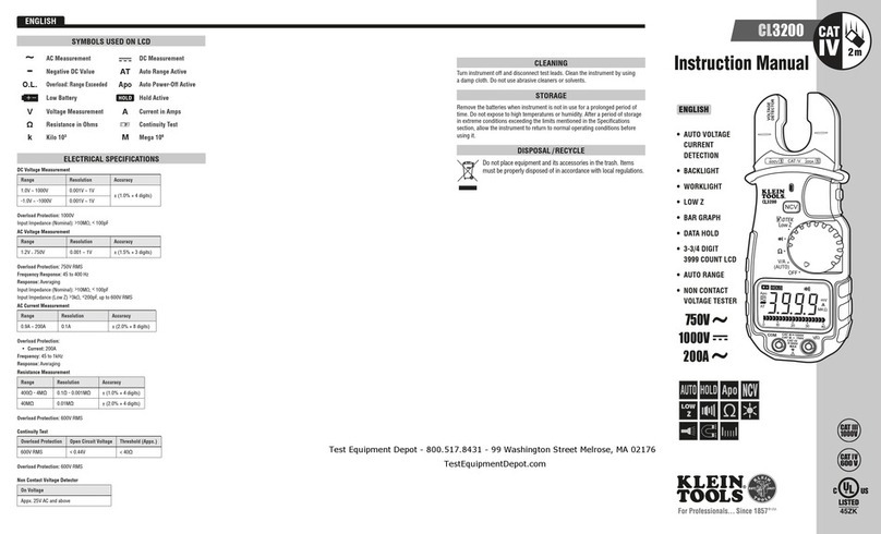
RND 365-00006 User manual

USER MANUAL – BEDIENUNGSANLEITUNG – ANVÄNDARMANUAL
RND 365-00006
AC / DC Clamp meter (p.2)
AC / DC-Zangenmessgerät (S.18)
AC/ DC Strömtång(S.36)

2
English
Read First
Safety Informaon
To ensure safe operaon and service of the Tester, follow these instrucons.
Failure to observe warnings can result in severe injury or death.
WARNING
Individual protecve equipment should be used if HAZARDOUS LIVE parts in the installaon
where measurement is to be carried out could be ACCESSIBLE.
CAUTION
If the equipment is used in a manner not specied by the manufacturer, the protecon
provided by the equipment may be impaired.
WARNING
• Always use proper terminals, switch posion, and range for measurements.
• To reduce the risk of re or electric shock, do not expose this product to rain or moisture.
• Verify the Meter operaon by measuring a known voltage. If in doubt, have the Meter
serviced.
• Do not apply more than the rated voltage, as marked on Meter, between terminals or
between any terminal and earth ground.
• Verify the Meter’s operaon by measuring a known voltage. If in doubt, have the Meter
serviced.
• Do not apply more than the rated voltage, as marked on Meter, between terminals
or between any terminal and earth ground.
• To avoid false readings that can lead to electric shock and injury, replace baery as soon
as low baery indicator.
• Do not use Meter around explosive gas or vapor.
• When using test leads or probes, keep your ngers behind the nger guards.
• Remove test lead from Meter before opening the baery door or Meter case.
• Use cauon with voltages above 30 Vac rms, 42 Vac peak, or 60 Vdc. These voltages pose
a shock hazard.

3
Symbols as marked on the Meter
and Instruction manual
Risk of electric shock
See instrucon manual
DC measurement
Equipment protected by double or reinforced insulaon
Baery
Fuse
Earth
AC measurement
Conforms to EU direcves
Do not discard this product or throw away.
CAUTION
• Probe assemblies to be used for MAINS measurements shall be RATED as appropriate for
MEASUREMENT CATEGORY III or IV according to IEC 61010-031 and shall have a voltage
RATING of at least the voltage of the circuit to be measured.
• Do not expose Meter to extremes in temperature of high humidity.

4
Power On/O
The Meter displays Baery Capacity when powering up. Please replace the baery when <
10% is shown.
CAUTION
The Tester powers up in Ω / connuity mode.

5
Auto Power O
Auto Power O Disable
Turn o the meter and press Power buon unl “APO” segment ashes 3 mes.

6
CAUTION
Do not use the Meter when “FAIL” is shown. Undiscovered failure could exist even “FAIL” is
not shown.
Self-Testing Aid
Do not measure while powering up, it will cause Self-Tesng failure.
CAUTION
If the meter is used in the vicinity of equip- ment which generates electromagnec
interference, the display may become unstable or the measurements shown may be
subject to large errors.

7
AC V/ DC V
CAUTION
When connecng the test leads to the circuit or device, connect the black lead before the
red lead ; when removing the test leads, remove the red lead before the black lead.

8
Input Impedance
≥ 6K for input voltage up to 30V. Impedance increase with input voltage to approximate
420KΩ at 1000V.
WARNING
Do not apply more than 1000VDC / 1000VAC VAC between Tester terminal and earth
ground.

9
Resistance

10
Continuity

11
Diode

12
Smart Hold
Data Hold is not available when “OL KΩ” displayed with no input signals.
The internal sounder will operate connuously with LCD display ashing in two situaons
in the Data Hold mode:
1. The Meter measure a dierent signal from the LCD reading.
2. The measured signal is the same unit as the LCD reading and is larger 50 counts than the
LCD reading.

13
AC A
CAT.IV600V With
respect to earth for
the jaw.
Barrier for Hand
Guard
Do not hold the
meter across the
Barrier.
I+(-I)=0

14
WARNING
The VoltSense LED indicates the electric eld. If the VoltSense LED is not on, voltage could
sll be present.
Back Light On/O
VoltSense

15
Baery Replacement
Maintenance
Do not aempt to repair this Tester. It contains no user-serviceable parts. Repair or serving
should only be performed by qualied personnel.
Cleaning
Periodically wipe the case with a dry cloth and detergent do not use abrasives or solvents.

16
Specications
General Specications
LCD display digits : 9999 digit large scale LCD readout.
Overrange display:“OL” is displayed for “Ω” and “V” funcon, shows the real value for “A”
funcon.
Conversion Rate : 2 ( mes / second ) .
Dimensions (W x H x D): 54mm x 193mm x 31mm
Weight: 280g including baery.
Power Requirement: AAA Size Baery 1.5V x 2.
Maximum Conductor Size: 16mm diameter.
EN61010-1
EN61010-2-032,
EN61010-2-033,
EN 61326-1
Overvoltage Category:
EN 61010-1 CAT.IV. 600V, CAT.III. 1000V
CAT Applicaon eld
I The circuits not connected to mains.
II The circuits directly connected to Low-voltage installaon.
III The building installaon.
IV The source of the Low-voltage installaon.
Environmental Conditions
Indoor Use.
Polluon degree: 2
Operang altude: 2000m (6562 )
Operang temperature: 0°C ~ 30°C (≤80% RH),
30°C ~ 40°C (≤75% RH),
40°C ~ 50°C (≤45%RH)
Storage temperature:
-20°C to 60°C, 0 to 80% R.H. (Baeries not ed).
Temperature coecient:
0.2 x (Spec.Accy) / °C, < 18°C or > 28°C .
Shock vibraon: Sinusoidal vibraon per MIL-PRF- 28800F (5 ~ 55 Hz, 3g max.)
Drop Protecon: 4 feet drop to hardwood on concrete oor.

17
Electrical Specications
Accuracy is given as ±(% reading + number of digits) at 23°C ± 5°C < 80%RH. Accuracy is
specied for a period of one year aer calibraon.
AC Funcon
ACV and ACA specicaons are ac coupled, true R.M.S.
The crest factor may be up to 3.0 as 4000 counts.
For non-sinusoidal waveforms, Addional Accuracy
by Crest Factor (C.F.): Add 3.0% for C.F. 1.0 ~ 2.0.
Add 5.0% for C.F. 2.0 ~ 2.5.
Add 7.0% for C.F. 2.5 ~ 3.0.
Range Resoluon Accuracy
2.1 V ~ 1000 V 0.1 V ± (0.3% + 2d)
-0.7 V ~ 1000 V 0.1 V ± (0.3% + 2d)
DC Voltage
Range Resoluon Accuracy
1.3V~1000V 0.1 V ± (0.9% + 3d)
(50Hz~60Hz)
± (1.5% + 3d)
(61Hz~500Hz)
AC Voltage
Input Impedance: > 6kΩ for input voltage up to 30V. Impedance increases to approximate
420kΩ at 1000V.
Overload Protecon: AC 1000Vrms, 1000Vdc
Maximum Operaon Time: 30sec.for more than 30V.
Input Impedance: > 6kΩ for input voltage up to 30V. Impedance increases to approximate
420kΩ at 1000V.
Overload Protecon: AC 1000Vrms, 1000Vdc.
Maximum Operaon Time: 30sec.for more than 30V.

18
Range Resoluon Accuracy
0Ω~10kΩ 1Ω ± (0.9% + 2d)
Resistor / Connuity
Range Resoluon Accuracy
0.4V~0.8V 0.1 V ± (1.0% + 3d)
Diode
Overload Protecon: AC 1000Vrms, 1000Vdc.
AC Current
Adjacent Conductor Inuence: < 0.08A/A.
Frequency Response: 50 ~ 60Hz (Sine Wave)
VoltSense: 80V ~ 1000V AC with 50Hz ~ 60Hz.
Connuity: Built-in buzzer sounds when measured resistance is less than 25Ω and sounds
o when measured resistance is more than 400Ω, Between 25Ω to 400Ω the buzzer maybe
sound or o either.
Overload Protecon: AC 1000Vrms, 1000Vdc.
Maximum Open Voltage: 1.6V.
Range Resoluon Accuracy
1.5A~200.0A 0.1 A ± (3.0% + 5d)
The proprietary informaon in this manual is protected by copyrights. Any photocopies,
reproducons or translaon to another language are not allowed unless it is permied.
And all rights are reserved.
The informaon in this manual is corre ct when prinng. However, RND will connuously
improve products and reserve the rights to change specicaons, equipment, and
maintenance procedures at any me without noce.

19
Deutsch
Lesen Sie zuerst die Sicherheitsinformationen
Sicherheitsinformaonen
Um einen sicheren Betrieb und Service des Testers zu gewährleisten, folgen Sie diesen
Anweisungen. Nichtbeachtung von Warnungen kann zu schweren Verletzungen oder zum
Tod führen.
WARNUNG
Individuelle Schutzausrüstung sollte verwendet werden, wenn GEFÄHRLICHE unter Strom
stehende Teile in der Anlage, in der die Messung durchgeführt werden soll, ZUGÄNGLICH
sein können.
ACHTUNG
Wird das Gerät in einer vom Hersteller nicht spezizierten Weise verwendet, kann der
Schutz durch das Gerät beeinträchgt werden.
WARNUNG
• Verwenden Sie immer geeignete Klemmen, Schalterstellung und Reichweite für Messun-
gen.
• Um das Risiko eines Brandes oder eines elektrischen Schlags zu verringern, setzen Sie
dieses Produkt nicht Regen oder Feuchgkeit aus.
• Überprüfen Sie den Zählerbetrieb, indem Sie eine bekannte Spannung messen. Im Zweif-
elsfall hat das Messgerät gewartet.
• Nicht mehr als die am Messgerät angegebene Nennspannung zwischen Klemmen oder
zwischen Klemme und Erdung auragen.
• Um falsche Messwerte zu vermeiden, die zu elektrischen Schlägen und Verletzungen
führen können, ersetzen Sie die Baerie sobald die Baerieanzeige leer ist.
• Verwenden Sie das Gerät nicht in der Nähe von explosionsfähigem Gas oder Dampf.
• Bei der Verwendung von Messleitungen oder Sonden, halten Sie die Finger hinter den
Fingerschutz.

20
ACHTUNG
• Vor dem Önen des Baeriefachs oder des Messgerätes die Testleitung vom Messgerät
enernen.
• Vorsicht bei Spannungen über 30 VAV RMS, 42 VAC peak oder 60 VDC. Diese Spannungen
stellen eine Schockgefahr dar.
• Sondenanordnungen, die für Hauptspannungs-Messungen verwendet werden sollen,
sind nach Maßgabe der IEC 61010-031 entsprechend der MESSKATEGORIE III oder IV zu
bewerten und müssen eine Spannung aufweisen, die mindestens die Spannung der zu
messenden Schaltung beträgt.
• Setzen Sie das Messgerät nicht extremen Temperaturen bei hoher Lufeuchgkeit aus.
Symbole auf dem Messgerät und
Bedienungsanleitung
Gefahr eines elektrischen Schlags
Siehe Bedienungsanleitung
DC-Messung
Ausrüstung, die durch doppelte oder verstärkte Isolierung geschützt ist
Baerie
Sicherung
Erde
AC-Messung
Entspricht den EU-Richtlinien
Verwerfen Sie dieses Produkt nicht oder werfen Sie weg.
Table of contents
Languages:
Other RND Measuring Instrument manuals
Popular Measuring Instrument manuals by other brands
EmerCom Technologies
EmerCom Technologies EMC-ALRM user guide
Pfeuffer
Pfeuffer HE lite operating instructions
Ellipse Security
Ellipse Security UNV OTC-513 quick guide

Katronic
Katronic KATflow 200 operating instructions
Sierra
Sierra MaxTrak 180 Series quick start guide
THORLABS
THORLABS NPL Series user guide
