Road Rover i10 Platform User manual

Service Manual for VW

Hardware
I10 Platform Preview
Structure and Design ……………………………………………………………………………………… 01
Connecters and Pin Diagram ………………………………………………………………………………….…02
Cables ………………………………………………………………………………………………………………….…02
System Configuration………………………………………………………………………………………………..03
Function and Features……………………………………………………………………………………………….04
Fundamental Performance and Parameter………………………………………………………………...05
……….
Main Board
Chips and Circuit Analysis
U13(LM3S1793)Microcontroller(MCU)…………………………………… 06
1.Power supply circuit for MCU……………………………………………………………………………….…06
2.B+3.3V power supply for MCU……………………………………………………………………………..…07
3.MCU clock circuit………………………………………………………………………………………………....…07
4.MCU reset circuit………………………………………………………………………………………………....…07
5.ACC detection circuit………………………………………………………………………………………………08
6.MCU Situation Analysis after Working Properly…………………………………………………..…08
7.System main power supply………………………………………………………………………………………09
8..Data bus works properly…………………………………………………………………………………………12
9.U16 Digital audio processing chip…………………………………………………………………………13
……………………………………………………………………………………….…05
……………………….…
10.U25 Central/Bass Operational Amplifier………………………………… 22
11.U24 CCD Switch Chip……………………………………………………………………………………………23
12.DVD Power Supply………………………………………………………………………………………………...25
13. Hand Brake Circuit Analysis………………………………………………………………………………….27
14. Remote Control Circuit Analysis……………………………………………………………………………27
15. SWC(Steering Wheel Control) Circuit……………………………………………………………………28
16. USB/iPod Power Supply Circuit…………………………………………………………………………….28
17. ILL (Illumination) Circuit……………………………………………………………………………………….29
……………………………
Contents
Contents
Navigation Board
1.Main power supply circuits on navigation board………………………………… 31
2.Main chips on navigation board…………………………………………………………………………………33
1. U8 CPU………………………………………………………………………………………………………………………33
2.U12、U13、U31、U32 DDR RAM(256M)………………………………………………………………...34
3.Flash (256M) ………………………………………………………………………………………………………………34
4.U29 (Expanded Memory) ……………………………………………………………………………………………35
5.U14 TW8816-Display Driver Chip………………………………………………………………………………35
6.Display Screen……………………………………………………………………………………………………………37
7.Touch screen……………………………………………………………………………………………………….………39
8.USB………………………………………………………………………………………………………………………..……40
9.SD Card………………………………………………………………………………………………………………….……41
10.Bluetooth …………………………………………………………………………………………………………………41
11.U27 Bluetooth Audio Amplifier ………………………………………………………………………….……43
12.Bluetooth Audio Switching Chip…………………………………………………………………………….…43
13.U20 Audio Decode Processing Chip…………………………………………………………………….……43
14.U22 GPS Module………………………………………………………………………………………………………45
…………………..…

www.roa drover.cn/e
Troubleshooting Guide
Troubleshooting Methods and Steps
General regulation………………………………………………………………………………………………………………46
General troubleshooting methods………………………………………………………………………………………46
Common failure and solutions ……………………………………………………………………………………………47
1.Cannot power on (black screen) ………………………………………………………………………………………47
2.All functions have no sound……………………………………………………………………………………………..50
3.Radio doesn't work & no sound………………………………………………………………………………………..51
4.DVD Failure (blue screen/no sound/no image/no color) …………………………………………………52
5.TV/AUX/iPod no sound…………………………………………………………………………………………………….54
6.Displaying problem………………………………………………………………………………………………………….55
7.Reverse problem……………………………………………………………………………………………………………...55
8.Handbrake doesn't work…………………………………………………………………………………………………..56
9.iPod cannot work properly………………………………………………………………………………………………..57
10.Cannot recognize USB device…………………………………………………………………………………………58
11.Remote control doesn't work…………………………………………………………………………………………58
12.SWC doesn't work…………………………………………………………………………………………………………..59
13.White screen/ blurred screen …………………………………………………………………………………………59
14.Bluetooth cannot be connected/ cannot search any Bluetooth device…………………………..63
15.The receiver cannot hear any sounds or noises exist when call somebody via Bluetooth 64
16.Hear nothing when you play Bluetooth music (A2DP) or call somebody via Bluetooth….64
17.No sound when you play MP3/MP4 or in navigation mode…………………………………………….65
18.GPS cannot get the position……………………………………………………………………………………………66
19.Screen Color Bias…………………………………………………………………………………………………………….67
20.Touch screen doesn't work ……………………………………………………………………………………………..69
21.Button lights cannot work……………………………………………………………………………………………...69
www.roa drover.cn/e
i10 PLATFORM
HARDWARE
01
Basic Information
All the units based on I10 platform adopt a brand new structure engineering design,
which makes the products have a better look, a better performance.
Side View
Structure & Design
Front Panel
DVD PART
Main Part
Front Panel: Navigation Board,LED Screen,Touch Screen,Plastic Frame And
Holding Covers included.
DVD Part: DVD Loader and holding covers included.
Main Part: Main board and holding covers included.
Front View

HARDWARE
www.roa drover.cn/e www.roadrover.cn/e
02
i10 PLATFORMi10 PLATFORM
HARDWARE
03
Connecters & PIN Diagram
Cables
1. Rear camera cable----input the video
of rear camera; input a reverse trigger;
provide power for rear camera.
GND
+12V
Reverse
CCD-IN
2. iPOD cable-----connectivity to IPOD,IPAD,IPHONE, play and control music
from I10 unit.
3. USB cable-----use for USB devices.
4. Front camera cable----- input the video of rear camera; provide power for rear
camera.(This function can be enabled by a special software if needed)
GND
+12V
Video-IN
5. Subwoofer pre-out cable---Pre-outs for subwoofer
and center signal; provide a trigger for external
amplifier. This cable is special for car audio tuning
to realize a real 5.1 channel sound effect.
Amp Control
Center out
Sub-woofer
6. Microphone cable-----audio input for Bluetooth.
7. TV input cable-----audio and video input from other
sources, mainly used for external TV audio and video
input.
R-IN
L-IN
Video IN
8. Video output cable-----mainly used for headrest
monitor, provide video from DVD,AV-IN,
(Internal TV—developing),(ipod,ipad,
iPhone Video—developing).
R-OUT
L-OUT
Video OUT
9. Surround pre-outs(4 SP)----Used when the
user wants to connect external 5.1 amplifier. RR OUT
RL OUT
FR OUT
FL OUT
10. GPS cable----receive signals from satellite to fix the position.
System Configuration
1. CPU: 600MHz ARM11+300MHz DSP
2. DDR1: 128M\256M
3. FLASH: 256M\128M
4. INAND: 4G---32G
5. RADIO: NXP Ultra low intermediate frequency digital radio modem
6. AUDIO DSP: NXP 135MHz float DSP
7. MCU: TI 32bit microcontroller\bus transceiver
8.Amplifier: ST7801 digital input, integrated HIFI (high fidelity) DAC
(digital-to-analog converter), adopt MOSFET as the power output

HARDWARE
www.roa drover.cn/e www.roadrover.cn/e
04
i10 PLATFORMi10 PLATFORM
HARDWARE
05
Functions and Features
1. Standard power interface, no damage to plug with the original car
2. Support dual antenna interface, transfer-free
3. Adopt Germany FAKARA standard radio connector, enhance the sensitivity and
stability for the GPS reception.
4. Support front\rear camera(options)
5. Support dual USB 2.0& USB 1.1
6. Support external microphone
7. Support two AV outputs
8. Support CMMB\DVB-T\ISDB-T digital TV and analog TV
9. Connect and charge iPhone \ iPod \iTouch
10. Support Surround pre-out
11. Support central and subwoofer output
12. Support AUX input
13. Support 3D real view navigation
14. Support multi navigation software
15. Support DVD\CD\CD-R\CD-RW format and MP4,WMA,WAV and so on.
16. Radio (support RDS, including AF,TP,TA,PTY function)
17. Bluetooth (support phonebook function)
18. Support IPOD,IPHONE operation from the touch screen
19. Support file explorer
20. Support multi language and theme, the background theme can be customized.
21. Air-conditioner information display synchronization
22. Multi time zone selection, support 12\24hour mode
23. backlight adjustable,day/night mode
24. support original parking sensor and rear image display, easy to switch from
parking sensor image to rear view image
25. Dynamic spectrum display
26. 9 bands EQ free choice, 5 DSP sound effect selection
27. Unique spatializer, provide 5 sound field position selection
28. Sound pressure contour control
29. Button beep sound
30. 5.1 channel Real mode output, output voltage is 4Vrms(volts root mean square)
maximum output 8V
31. Dynamic treble\bass control, central frequency and gain adjustable
32. Bass output, provide 10 cut off frequency points, gain(6DB) adjustable, phase
(0-180) adjustable
33. Central output, provide 7 alternative cut off frequency points, gain(6DB)
adjustable
34. Indirect touch technical for CD,realize track selection directly
Fundamental Performance and Parameter
a. CD (internal amplifier output, standard output)
SNR: ≧92B
DYNAMIC: ≧90Db
DISTORTION THD+N: 0.05%
b. Radio (internal amplifier output, standard output)
SNR: ≧75Db
Sensitivity S\N 30DB: -3 dBuv
c. MP3(internal amplifier output, standard output)
SNR: ≧80db
DYNAMIC: ≧75db
DISTORTION THD+N: 0.05%
Main Board
Radio antenna socket
Function Socket Power & Speakers Socket
Cn8 DVD Connecting Port
Q1 P-Channel
Enhancement Mode
MOSFET
U19 Digital input quad
power amplifier
U11 Synchronous
Rectified step-down
converter
U25 operational amplifier
for Ex. Bass ¢ral
U17 operational amplifier
for Ex. Amp
U6 Low Dropout Voltage
Regulator with Shut Down
Switch
Q22 DSP1.8V Supplier
CN6 Front Panel Connecting Socket
U14 Erasable
Programmable
ROM(EPROM)
U13 Microcontroller(MCU)
U20 CANBUS Transceiver
U16 DSP
Processor IC
Front/Rear Video IC
U26 A/V Switcher
CN9 Built-in TV Socket
USB.IPOD Power Supply IC
Digital Radio Module
Chips and Their Functions on Main Board

HARDWARE
www.roa drover.cn/e www.roadrover.cn/e
06
i10 PLATFORMi10 PLATFORM
HARDWARE
07
1. U13(LM3S1793)Microcontroller(MCU)
1. Function: Control the power supply and all the functions for the whole system.
2. Normal Operating Conditions:
2.1 Power supply circuit
2.2 Crystal oscillator oscillation circuit
2.3 Reset circuit
2.4 ACC detection circuit
2.5 Correct Software
Operating Conditions Analysis for MCU
2.1 Power supply circuit for MCU
The main power supply circuit for MCU can be divided into two parts.
a. MCU need a 3.3V Power supply(MCU_+3.3V).
The BATT+12V goes to U6, then U6 offers a 5V voltage at pin 4 to U1, U1 provides
the 3.3V at pin 5 to MCU. As shown below.
B+12v input to U6 5V
MCU3.3V
b. B+3.3V for MCU(MCU BATT_+3.3V).
The Batt+12V goes to the pin 3 of U8, and U8 offers a 5V voltage to U2, then U2
output the B+3.3V to MCU. As shown below.
B+12V
5V
MCU B+3.3V
2.2 MCU clock circuit
There are two oscillation circuits for MCU, two crystal oscillators are included,
one is 16 MHz and the other is 4.194304 MHz.
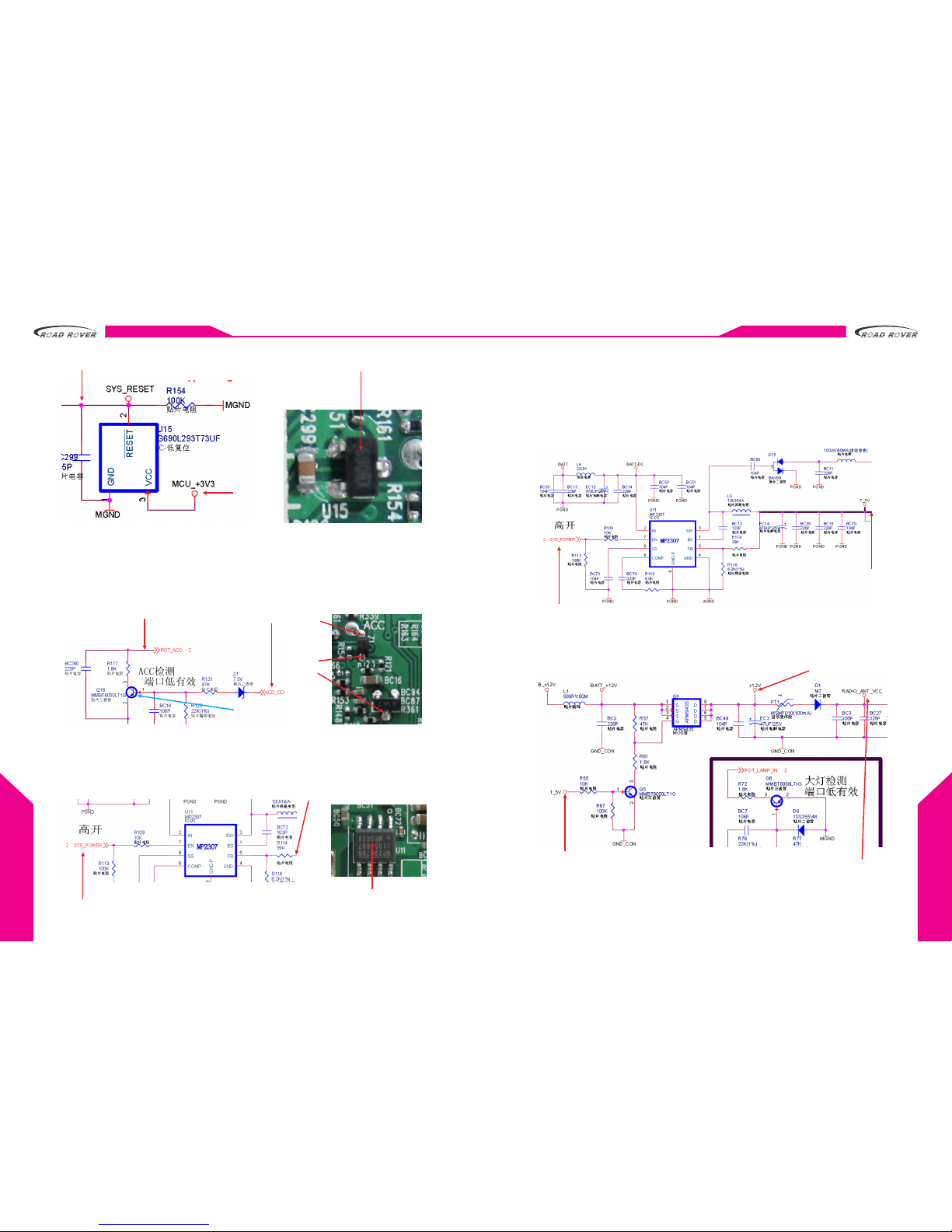
2.3 MCU reset circuit
U15 is a reset chip for MCU, it works when you press the reset button and pin 2
becomes low level. It doesn't work if the power at pin 2 is a high level.
HARDWARE
www.roa drover.cn/e www.roadrover.cn/e
08
i10 PLATFORMi10 PLATFORM
HARDWARE
09
3.3V
3.3V
U15 Reset IC
2.4 ACC detection circuit
ACC_CO input a 12V to the voltage-regulator diode Z1, after Z1 and R121, the
voltage at the base of Q18 will be 0.58V, then collector and emitter will be short
circuit. Then the voltage of POT_ACC will be changed from high level to 0V (low
level) and it will be activated.
Effective when low level detected
Q18 Base 0.58V
External ACC 12V
Z1 andQ18
MCU Situation Analysis after Working Properly
1. When MCU is working, it will send a 3.3V high level signal (SYS-POWER) to pin 7
of U11, that makes U11 start work and provide a 5V for front panel.
SYS_POWER 3.3V from MCU high level
Front panel power supply T_5V
U11 Synchronous Rectified
step-down converter
2. System main power supply
The system main power supply is composed of T_5V、12V、9V、+5V、+7.5V、-7.5V、
+5V、VCC 5V
a. System power supply T_5V
T5V is the power supply for front panel, CCD circuit, AV switching chip(U26),
Q1 stabilizing circuit, DSP voltage-stabilizing circuit, fan power supply circuit,
and USB/ iPod circuit.
SYS_POWER 3.3V from MCU high level
T_5V power supply
b. System power supply 12V
The 12V generated by Q1, it will offer power for TV module, CCD, radio antenna,
external amplifier, and the system 9V circuit.
When T_5V offered,
the base and emitter
of Q5 become short
circuit,Q1 starts
working and provide
a 12V voltage
12V
Power supply
for radio antenna

HARDWARE
www.roa drover.cn/e www.roadrover.cn/e
10
i10 PLATFORMi10 PLATFORM
HARDWARE
11
c. System power supply circuit M_+9V
After the MOSFET Q1, there is a 12V offered to U4, then U4 will give a 9V to radio
and DVD part as a driver power supply.
12V from Q1 9V for radio and
DVD circuit part
d. System power supply TV_TUN_12V
The 12V voltage comes from Q1 goes to PT3 and D3, then a stable 12V is available
for external TV box.
12V from Q1
TV 12V for
external TV
box
e. System power supply CCD_VCC(10V)
U35 get a stable voltage 12V from Q1, then it provides a stable voltage around
10V as the power supply for rear camera.
12V from Q1 6.5V for
rear camera
12V from Q1 12V for
rear camera
f. Radio power supply RADIO_+5V
When U30 get a normal 9V at 1st and 2nd pin, it will provide a stable 5V for radio
at 4th pin.
9V from 4th pin of U4 +5V for radio
g. Positive power supply for operational amplifier +7.5V
When the 9V go through a current-limiting resistances, it will be changed to 7.5V
as a power supply for the operational amplifiers (U17&U25).
9V from U4
+7.5V for operational
amplifiers (U17&U25)
h. Negative power supply for operational amplifier -7.5V
When 5V AC signal go through D15, it will be changed to negative voltage -5V,
then the diode will double the voltage to -10V, after a current-limiting resistance,
it will be reduced to -7.5V as a power supply for operational amplifiers (U17&U25).
A 5V AC signal from U11
Compound diode voltage-doubling circuit -7.5V for operational amplifiers (U17&U25)
HARDWARE
www.roa drover.cn/e www.roadrover.cn/e
12
i10 PLATFORMi10 PLATFORM
HARDWARE
13
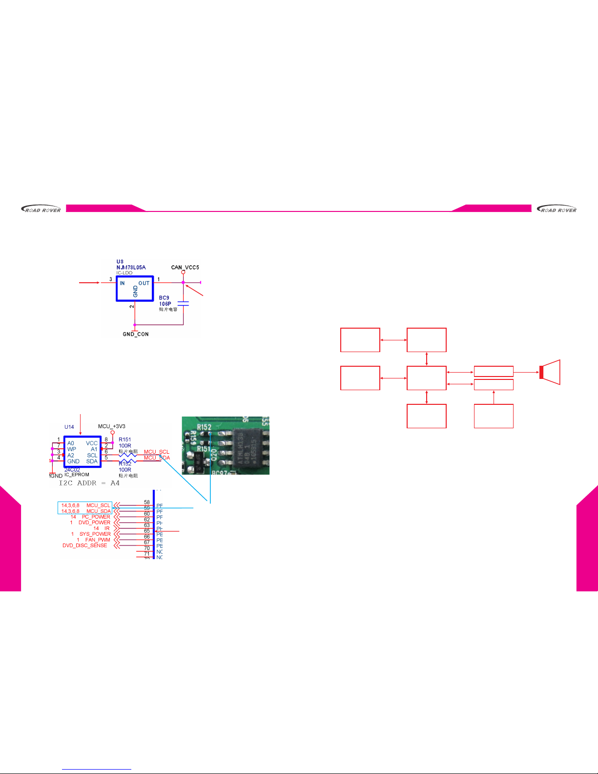
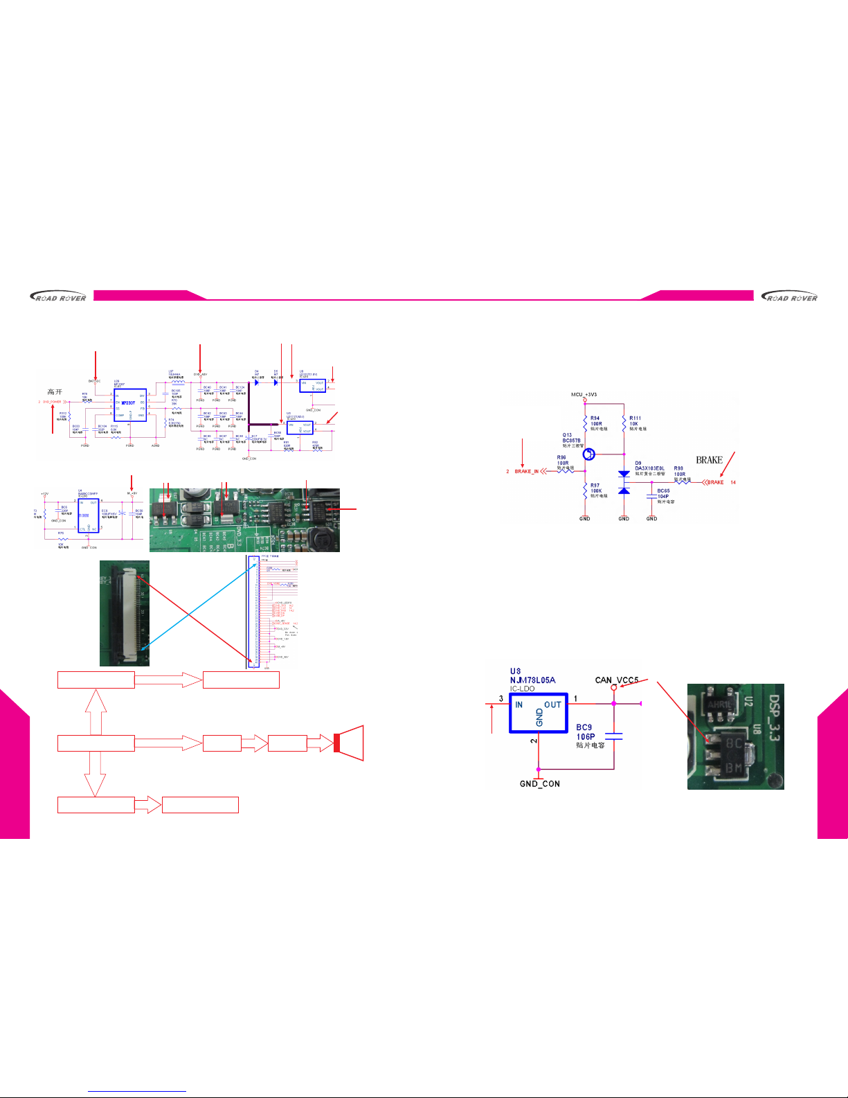
i. System power supply CAN_VCC(5V)
U8 gets the normal B+12V at 3rd pin, it will provide a 5V voltage for CANBUS
transceiver, remote control receiver. So when the ACC of the vehicle is ON,
we can use the remote control to power on the unit.
BATT_+12V
5V for CANBUS transceiver
and remote control receiver
3. Data bus work properly
Date bus is the serial data bus which provides a way to sending and receiving
data or signals for MCU. MCU communicates with EPROM (U14) via data bus to
memorize the system working status, such as the system volume, OSD adjusting
info, power-on/off mode etc. The data bus connects with different parts and
controls different functions. For example, DSP(U16), AMP, TW8816, and AV
switching chip(U26).
Erasable programmable Rom
Data Bus 3.3V
MCU CANBUS Port
A short Summar y for MCU
Here is a short summary and some extra information for MCU.
a. The MCU_+3.3V goes to MCU and a lot of other circuits. Such as steering wheel
control circuit, data bus circuit, reset circuit, AUX detecting circuit, handbrake
circuit etc.
th th th
b. The BATT_+3.3V goes into MCU via pin 50 ,51 ,55 .
th th
c. The crystal oscillator XT1is connected to 48 and 49 pin of the MCU, and the
th th
XT2 is connected to 52 and 53 .
d. POT_ACC is connected to 46th pin of the MCU.
e. MCU block diagram.
Digital radio
module DSP
MCU
EPROM
AMP
AV switcher
Video
processor
TW8816
AV/TV/
IPod/
AUX
Chips and Functions on Main Board
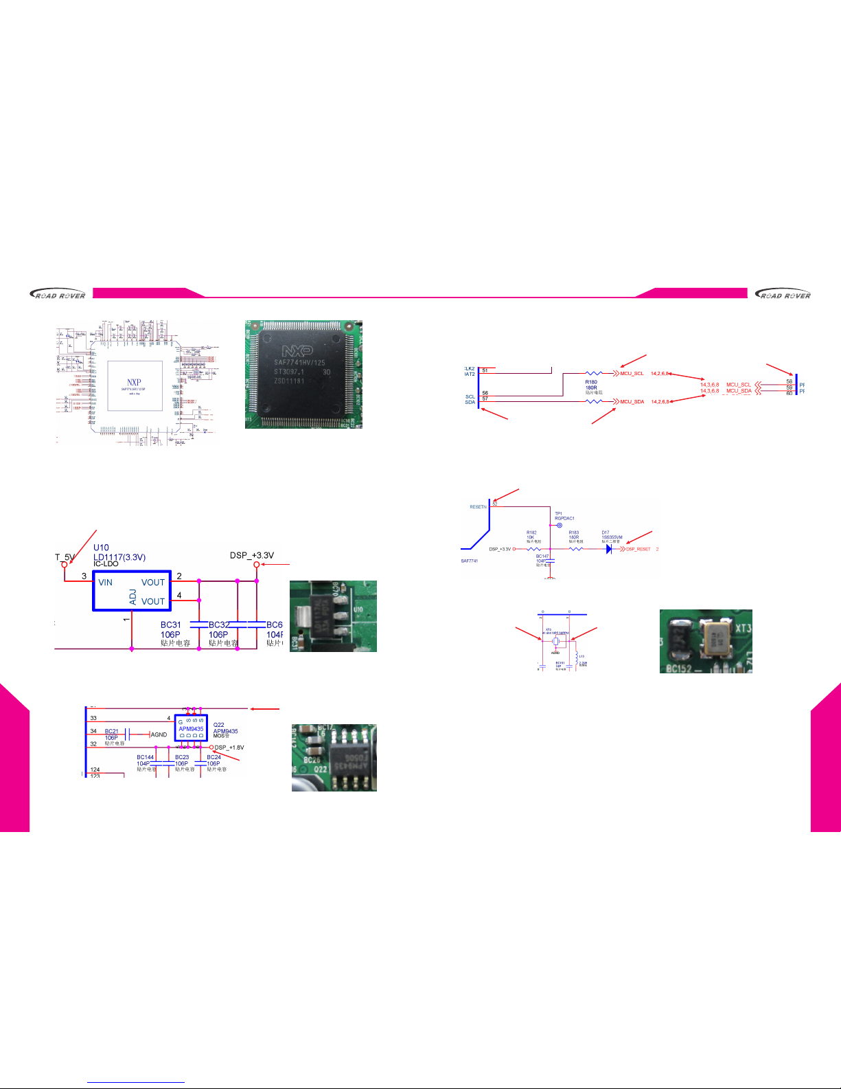
2. U16(NXP SAF7741)digital audio processing chip.
1. Function: DSP digital audio processing and digital radio tuning
2. Normal operating condition:
2.1 Correct power supply
2.2 MCU data bus working properly
2.3 DSP reset
2.4 oscillating circuit working properly
HARDWARE
www.roa drover.cn/e www.roadrover.cn/e
14
i10 PLATFORMi10 PLATFORM
HARDWARE
15
2.1 DSP power supply circuit
The main power supply circuit for DSP audio processing chip can be divided
to 2 parts:
a. DSP power supply1 ( ) DSP_+3.3V
When U10 gets T_ 5V voltage at 3rd pin, it will offer a stable 3.3V to DSP.
5V from U11
3.3V goes to Q22
b. DSP power supply1 ( )DSP_+1.8V
When DSP_+ 3.3V is correct, Q22 can start work and provide a stable 1.8V to
DSP3.3V comes from U10DSP.
DSP3.3V comes from U10
DSP1.8V
power supply
2.2 DSP serial data bus
DSP serial data bus is controlled by MCU, all the functions share the same way to
communicate with MCU.
3.3V
3.3V
DSP CANBUS Port
MCU CANBUS Port
2.3 DSP reset
The DSP reset is controlled by MCU, there is a 3.3V voltage at reset pin of the MCU,
when you press the reset button, the voltage there will be changed to low level,
then the MCU reset. Then DSP chip will follow the step and reset.
Low level reset
3.3V from pin 75 of MCU
2.4 Clock oscillating circuit
This is a clock oscillating circuit, and the oscillator frequency is 41.6MHz.
1V
1V
A short Summar y for DSP
Here below is a detailed signal flow instruction for DSP audio processor.
a. PC Audio Processing
PC analog audio signal, which comes from audio processor( )on
th th
navigation board, goes to 11 and 14 pin of DSP chip as Audio_R channel
th th
and Audio_L channel, 12 and 13 pin of DSP chip are Audio_GND. There are
4 different PC audio signals, included.
WM8758
MP3, MP4, GPS, Bluetooth
b. DVD Audio Processing
th th
The DVD goes to 24 and 25 pin of the DSP chip.digital audio signal
c. Digital Radio Audio Processing
The digital audio signal of the radio will go directly to the DSP chip.

HARDWARE
www.roa drover.cn/e www.roadrover.cn/e
16
i10 PLATFORMi10 PLATFORM
HARDWARE
17
d. Other Audio Source Processing
Besides, there are still some other audio sources like AV, TV, CDC, XM Radio,
phone,AUX and iPod to be processed. All these audio sources will be
th th
processed by the A/V switcher (U26) first and then go to 5 and 8 pin of DSP
th th
chip as Audio_R channel input and Audio_L channel input. 6 and 7 pin are
the Audio_GND.
AV TV iPOD AUX CDC
R2S11002AFT
DSP
WM8758B
BT MP3/4 GPS
TEF7000 AMP
3. U18 (NXP TEF7000) Digital Radio Chip
1. Function: Receive the external RF signal, and convert it to digital signal.
2. Normal operating conditions:
2.1 Correct Power supply
2.2 Data bus working properly
2.3 Data Clock is in order
2.4 Data transmission is in order
2.1 Radio Power Supply Circuit
A 5V voltage power supply is needed for the digital radio chip. When Q1 is
working, it will offer a +12V to U4, then U4 will output a stable 9V to U30.
Next,U30 will provide a stable 5V for the radio chip.
+12V comes from Q1
9V
5V for digital radio tuner
2.2 Radio Serial Data Bus
The radio serial data bus is controlled by DSP, not MCU. The automatic gain
control and digital signal demodulation are controlled by DSP.
1.2V for serial data bus
2.3 Radio Data Clock
3.3V for data clock control
2.4 Digital Signal Transmission
All the digital signal come from digital radio chip will be transmitted to DSP chip
for audio decoding.
Digital signal Transmission
Digital Radio Summary
The digital radio chip has a very close relationship with DSP chip. The radio chip
is tuned and controlled by DSP.
If the 5V power supply is correct, and antenna has a good connection, clock circuit
and data bus, peripheral circuits are all working normally, then radio chip can work
properly. Then it will transmit the RF signal to digital audio signal, which will be
inputted to DSP chip for audio output.

HARDWARE
www.roa drover.cn/e www.roadrover.cn/e
18
i10 PLATFORMi10 PLATFORM
HARDWARE
19
So,that means the radio chip must work with DSP chip. If the DSP module cannot
work normally, the radio cannot scan for any station.
TEF7000
CLKP
CLKN DSP AMP
radio antenna Speaker
4. U19(TDA7801) Digital Input Quad Power Amplifier
1. Function: digital audio input and amplification,
decrease noise and improve the sound quality.
2. Normal operating conditions:
2.1 Correct Power supply
2.2 Data bus working properly
2.3 Digital audio input
2.1 Correct Power supply
th st
The amplifier needs a 12V voltage power supply at 7 and 21 pin.
2.2 Data Bus working properly
The amplifier is controlled by MCU via data bus.
2.3 Digital Audio Input
The digital audio signal
comes from DSP processed
by amplifier and provide the
amplified signal for speakers.
st
1 pin GND
Pin 7 and 21
12V Amplifier
power supply
DSP audio input
Pin 5, 11, 12, 13
Voltage: 1.2V
Data Bus
MCU_SDA
MCU_SCL
3.3V
Audio signal for
speakers Pin 4, 6,
8, 10, 18, 20, 22,
24 Voltage: 6V
nd
2 pin
MCU control switcher
3V
5. U26(R2S11002AFT) AV Switcher
1. Function: Switch and transform the audio and video signals.
2. Normal operating conditions:
2.1 Correct Power supply
2.2 Data bus working properly
2.1 Correct Power supply
There are two main power supply for AV switching chip, one is A_+9V, the other
is T_5V.
A_+9V goes to L39
T_5V goes to L38.

HARDWARE
www.roa drover.cn/e www.roadrover.cn/e
20
i10 PLATFORMi10 PLATFORM
HARDWARE
21
2.2 Serial Data Bus
The AV switcher is controlled by MCU as well via data bus. Pin 51 and 52 is the
data bus port.
Data bus
Voltage: 3.3V
AV Switcher Summary
Responsible for some audio and video input, process and convert.
a. Audio:
The audio signal of CCD,AV, built-in TV, iPod, external TV, AUX go into the AV
switching chip first, then the MCU will decide if the signal should get access
to DSP chip or not.
b. Video:
The video signal of TV (EX/IN), DVD, iPod go to the switching chip first, after
a processing, the video will be transmitted to the system display or external
headrest screen.
AV/TV ipod AUX audio
AV/TV DVD ipod video
AV switcher
(U26)video Tw8816
headrest
image display
audio
DSP AMP
6. U17(TL084)operational amplifier for External
Amplifier
1. Function: process the audio signals from DSP and provide 4 pre-outs for
external amplifier.
2. Normal operating conditions:
2.1 Correct Power Supply
2.2 Audio signal input and output
2.3 EX AMP Control
2.1 Power Supply Circuit
There are two power supply for Audio operational amplifier chip. They are +7.5V
and -7.5V.
a. +7.5V
M_+9V
comes
from U4
+7.5V for
operational
amplifier U17

HARDWARE
www.roa drover.cn/e www.roadrover.cn/e
22
i10 PLATFORMi10 PLATFORM
HARDWARE
23
b. -7.5V
Bipolar diode
T_5V -7.5V for operational amplifier U17
2.2 Audio Signal Input and Output
Here are 4 audio channels inputs and outputs.
Input:
DSP_SL_IN DSP_SR_IN
DSP_FL_IN DSP_FR_IN
Output:
LEVEL_RL_OUT LEVEL_RR_OUT
LEVEL_FL_OUT LEVEL_FL_OUT
LEVEL_RL_OUT
DSP_SL_IN
DSP_SR_IN
LEVEL_RR_OUT
LEVEL_FL_OUT
DSP_FL_IN
DSP_FR_IN
LEVEL_FR_OUT
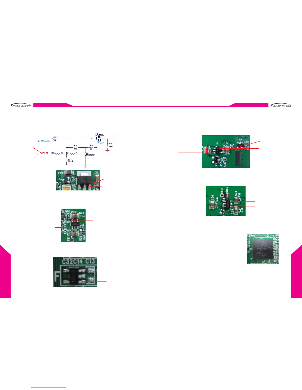
2.3 Control Circuit for External Amplifier
This circuit can provide a stable 10V for activating external amplifier. Every
time when you power on the system, MCU will keep giving a high level to the
control circuit to make it work.
EX AMP
control
wire, 10V
12V comes from Q1
Low level
High level from MCU chip
7. U25(NE5532)Central/Bass Operational Amplifier
1. Function: This IC is a high-performance and low noise dual OPAMP IC. That means
it can do both central and bass process.
It will process the middle/bass audio signal from DSP, then offer the signal to
external amplifier.
2. Normal operating conditions:
2.1 Correct Power Supply
2.2 Audio signal input and output
2.1 Correct Power Supply
Pin 8 of the operational amplifier should be +7.5V.
2.2 Audio Signal Input and Output
a. Central Input & Output
The central audio signal goes to 3rd pin of U25A. After processing,
LEVEL_Central_Out will go out from 1st pin.
DSP central
audio input
Power supply +7.5V
Central
output
for external
AMP
b. Bass Input & Output
th
DSP bass audio signal input 5 pin,
th
LEVEL_SUB_OUT output 7 pin.
DSP Bass
audio input
Power supply +7.5V
Bass output
for external AMP
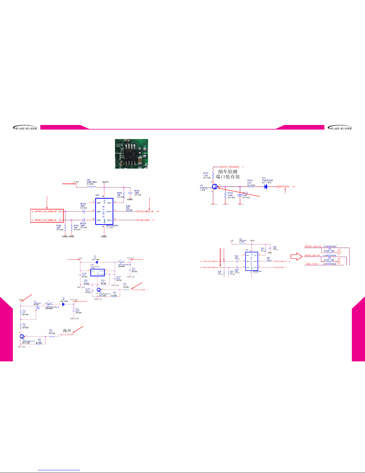
8. U24(BH76330)CCD Switch Chip
1. Function: Switch and transform the reverse camera video, front and rear camera
selection.
HARDWARE
www.roa drover.cn/e www.roadrover.cn/e
24
i10 PLATFORMi10 PLATFORM
HARDWARE
25
2. Normal operating conditions:
2.1 Correct Power supply
2.2 Correct CCD camera power supply
2.3 CCD trigger works properly
2.4 Video signal input & output
2.1 Power supply circuit
The power supply for CCD switch chip is 5V.
Front/rear camera video input
T_5V from U11
CCD video
Signal output
2.2 CCD Camera Power Supply
The CCD camera power supply (6.5V-toyota serials; 12V-others) can only be
activated when the vehicle is reversing.
+12V from Q1 CCD power
supply 6.5V
Activate when
low level from MCU
+12V from Q1
CCD power supply 12V
Activate when high level(3.3V) from MCU
2.3 CCD Trigger
When the vehicle is reversing, the reversing lamp will light up, this is because
there is a +12V voltage provided for the lamp. Meanwhile,the high level will
go to 1st pin of Q6 and reverse port will become low level trigger. Then MCU
get the reverse command and control the system turn to CCD image display.
When the car starts reversing,
the bass of Q16 is high level.(0.58V)
When MCU get the reverse
command, the system will
turn to CCD image display
2.4 Video Signal Input & Output
When the system turn to CCD image display, the reversing camera starts
working, the camera video signal will goes to CCD switch chip, then the
camera video signal will be transmitted to the video processor (TW8816)
on navigation board. After that, the signal will be processed and finally you
can see the camera image on screen.
Front/rear video input
CCD Switch Chip Summary
CCD switch chip can support both front camera video and rear camera video input
& output. If the video is comes from rear camera, MCU will select a channel for rear
camera video input and output. It's the same way for front camera.
At this moment, front camera function is not ready yet though the hardware can
support it already. Front camera displaying will be an optional function for
customers in the future via software update.
9. DVD Power Supply
HARDWARE
www.roa drover.cn/e www.roadrover.cn/e
26
i10 PLATFORMi10 PLATFORM
HARDWARE
27
There are 4 voltage supplies for DVD loader. They are 5V, 3.3V, 1.8V and 9V.
BATT 12V
MCU 3.3V
available
when disc
insert
5V power supply for DVD loader and 2 MOSFET
1.8V for main
chip on DVD
Loader
DVD_3.3V for
audio and video
processor and
flash of DVD
loader
M_+9V for
DVD loader
DVD_1.8V DVD 3.3V BATT 12V
DVD_POWER
DVD FPC connector
pin diagram
AV Switcher output headrest
CVBS
DVD Digital audio DSP AMP
video
TW8816 display
10. Hand Brake Circuit Analysis
When you pull up the hand brake, the pink BRAKE wire of our system will be
short circuit with GND, then the base of Q13 will get a voltage which is lower
than before then the emitter and collector will be short circuit, and BRAKE_IN
port will become high level. MCU will give a command to the application
software to do a brake disable action.
high level (2V) is effective.
goes to MCU hand brake
trigger por t brake cable
Hand brake pull up 3.3V
Hand brake pull down 0V
11. Remote Control Circuit Analysis
The infrared receiver module has 3 pins, one is for power supply (5v), the second
one is the communicating port with MCU, and the third is GND.
a. Power Supply for Infrared Receiver
When U8 get the BATT _12V, it will provide a 5V voltage for infrared receiver
module, then the receiver will stay in working mode.
BATT_+12V
input
5V for infrared receiver module

HARDWARE
www.roa drover.cn/e www.roadrover.cn/e
28
i10 PLATFORMi10 PLATFORM
HARDWARE
29
b. Single Infrared Receiving Serial Port
IR-OUT
GND
VCC---5V
IR 3.3V from MCU (Port 63)
12. SWC(Steering Wheel Control) Circuit
KEY_3 and KEY_4 are connected with AD cables (AD1, AD2), and they go
directly to the MCU chip. When you press the button on the steering wheel,
different level will be given to the AD ports (AD_3, AD_4) of MCU and MCU
will do corresponding response for different level.
MCU 3.3V output for
each line when there
is no button pressing
13. USB/iPod Power Supply Circuit
When U3 get a 5V voltage at 2nd pin, it will output a stable 5V to USB and
iPod at 6th and 7th pin.
USB_VCC (5V): provide a power supply for USB device or as a power source
for USB device charging.
iPod_5V: provide a power supply for iPod or as a power source for iPod
charging.
T_5V from U11
5V for USB
5V for iPod
14. ILL (Illumination) Circuit
a. Illumination Trigger Circuit
When headlamp or dashboard lights is switched on, the ILL wire (LAMP_IN) gets
a 12V voltage. Then the base of Q8 will get a 0.6V voltage (0V when ILL is off ),
then 2nd and 3rd Q8 will be in conductive state, POT_LAMP of the MCU will be
short circuit to GND, ILL detection port become low level.
0.6V
MCU ILL detection port
12V offered When
headlamp or dashboard
lights is switched on
b. Illumination Control Circuit
When MCU ILL port become low level, MCU will send a high level signal to Q15
to make it conductive between 2nd and 3rd pin. Then Q14 gets a low level at the
gate terminal and also be conductive, so LAMP_P port will get a 12V voltage for
the LED lights on the front panel.
12V for LED lights
+12V from Q1
12V for LED
lights on
front panel
It will discharge and
provide a short time
voltage for LED lights
when headlight/dash
board lights be turned off
High level from MCU chip

HARDWARE
www.roa drover.cn/e www.roadrover.cn/e
30
i10 PLATFORMi10 PLATFORM
HARDWARE
31
Navigation Board
DDR RAM
4*64M=256M
4G iNAND
flash
FL ASH storage
GPS positioning Chip
Audio processing Chip
Connector for left key board
Connector for main board
Connector for touch screen
Connector
for SD card
Display screen
driver IC
Connector for
display screen Connector for
touch screen
Connector for
main board
Connector For USB
BT module
USB driver Chip
Connector for
right key board
CPU
1. Main Power Supply Circuit On Navigation Board
The navigation board needs a 5V power supply, this voltage will be supplied
to U1,U2,U3,U4,U6,U7.
a. Power Supply Circuit---U1.
When Q2 get a 3.3V power supply, it will be breakover. Then U1 get the 5V
power supply, it will offer a stable 3.3V for CPU, FLASH, USB, audio processing
chip, iNAND.
Input 3.3V
BGA 3.3V 5V power supply for U1
b. Power Supply Circuit---U2
When U2 get the 5V power supply at 4th and 5th pin, it will output a stable
1.2V for CPU.
1.2V output BGA 3.3V
th th
5V power supply at 4 , 5 pin
HARDWARE
www.roa drover.cn/e www.roadrover.cn/e
32
i10 PLATFORMi10 PLATFORM
HARDWARE
33
c. Power Supply Circuit---U3
When Q4 get the 3.3V power supply, it will be breakover. Then U3 get the 5V
power supply at 3rd pin, it will provide a 2.6V for Q3, Q3 becomes conductive,
then DDR can get 2.6V power supply.
Input 3.3V
DDR 2.6V power
5V for U3 at 3rd pin
2.6V output at 2nd pin
d. Power Supply Circuit---U4
When U4 gets the 5V power supply at 1st pin, it will output a stable 3.3V for GPS
positioning chip.
5V power supply for U4
3.3V output for GPS positioning chip
e. Power Supply Circuit---U5
When U5 get a 3.3V power supply at pin1, it will provide a 1.2V voltage to FB3,
FB4, FB5 (magnetic bead) as the power supply for CPU.
1.2V output pin 5 3.3V power supply pin 1
3.3V for controlling pin 3
f. Power Supply Circuit---U6
st rd th
When D6 get a 5V input at the 1 and 3 pin, U6 will output a stable 3.3V at 5
pin to D7 and as a power supply for the batter y on the navigation board. This
part (U6, D7 & lithium battery) works as a RTC power-supply system to enable
the unit's memorizing function.
5V input 3.3V output
3V
g. Power Supply Circuit---U7
nd st rd th
2 pin is 5V input, 1 and 3 pin are for controlling, 4 pin outputs a 3.3V for
th
the USB power supply part of CPU, 6 pin provides a 2.5V for the button part
of CPU.
5V power supply 2.5V for button par t of CPU
3.3V for USB part of CPU
Main Chips on Navigation Board
1. U8 CPU
1.1 Function:
The main function of CPU is to control, operate,
and process all kinds of data. CPU has 3 parts:
control unit, logic unit, memory unit. It is in
charge of all the functions of the system, like
image displaying, GPS signal processing, USB,SD
card, iPod, MP3, MP4, GPS voice, Bluetooth, touch
control etc.
1.2 Operating Conditions:
a. The CPU needs three power supplies, they are 3.3V, 1.2V, 2.5V.
b. There are two CPU clock: the master clock and the vice clock. The frequency
of the master clock is 32.768KHZ and the vice clock is 12MKZ.
HARDWARE
www.roa drover.cn/e www.roadrover.cn/e
34
i10 PLATFORMi10 PLATFORM
HARDWARE
35
32.768KHZ 12MHZ
2. U12、U13、U31、U32 DDR RAM(256M)
2.1 Function
DDR is a random-access storage space, which can be randomly, individually
to access each memory cell through the instruction. It can do read and write.
Also can provide cache for CPU, which can make the system run in a smoother
state when you operate the system.
2.2 Operating Conditions:
a. Correct power supply (3.3V)
b. Connect with CPU core by exclusions.
64M*4 DDR
3.3V for DDR RAM
exclusions
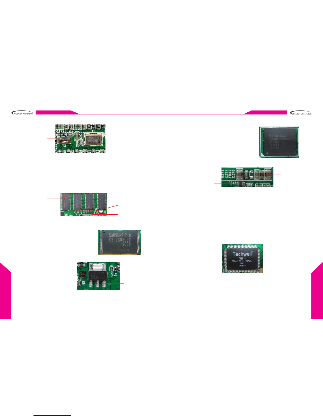
3. Flash (256M)
3.1 Function:
Flash is the ROM which is mainly used to store
the application software, music, video, picture
files and so on.
3.2 Operating conditions:
a. correct power supply (3.3V)
b. correct application software.
c. Connect with the CPU correctly.
3.3V output for flash 5V input for U1
4. U29 (Expanded Memory)
4.1 Function:
Expanded memory is used to extend
the memory of the device, which you
can store the mass storage files, e.g.
music, video and picture etc.
4.2 Operating conditions:
a. Power supply circuit work properly.
b. Normal Transfer with CPU
Fb41 3.3V for
expanded memory
chip
FB42 3.3V for
memory chip
5. U14 TW8816-Display Driver Chip
5.1 Function:
Tw8816 is the highly integrated multi-functional video decoder chip, which
include an 8-bit microcontroller and a CCFL (Cold Cathode Fluorescent Lamp)
controller. It's used to process the image signals, and provide right signals for
displaying, as well as processing some composite video signals. In order to
get a connectivity with kinds of single sources.
5.2 Operating conditions:
a. Correct Power supply
b. Clock frequency working properly.
c. Normal MCU date bus controlling
Table of contents
Other Road Rover Car Receiver manuals


