ROADWORX Lighting Stand 1 User manual

Lighting Stand 1
Lighting Stand
User Manual

Thomann GmbH
Hans-Thomann-Straße 1
96138 Burgebrach
Germany
Telephone: +49 (0) 9546 9223-0
Internet: www.thomann.de
04.12.2023, ID: 442430 (V2)

Table of contents
1 General information................................................................................................................................. 5
1.1 Symbols and signal words............................................................................................................... 5
2 Safety instructions..................................................................................................................................... 7
3 Features.......................................................................................................................................................... 9
4 Operation.................................................................................................................................................... 10
5 Technical specications....................................................................................................................... 15
6 Protecting the environment.............................................................................................................. 17
Table of contents
Lighting Stand 1 3
Lighting Stand

4Lighting Stand 1
Lighting Stand

1 General information
This document contains important instructions for the safe operation of the product. Read and
follow the safety instructions and all other instructions. Keep the document for future refer‐
ence. Make sure that it is available to all those using the product. If you sell the product to
another user, be sure that they also receive this document.
Our products and documentation are subject to a process of continuous development. They
are therefore subject to change. Please refer to the latest version of the documentation, which
is ready for download under www.thomann.de.
1.1 Symbols and signal words
In this section you will nd an overview of the meaning of symbols and signal words that are
used in this document.
General information
Lighting Stand 1 5
Lighting Stand

Signal word Meaning
DANGER! This combination of symbol and signal word indicates an
immediate dangerous situation that will result in death or
serious injury if it is not avoided.
CAUTION! This combination of symbol and signal word indicates a pos‐
sible dangerous situation that can result in minor injury if it
is not avoided.
NOTICE! This combination of symbol and signal word indicates a pos‐
sible dangerous situation that can result in material and
environmental damage if it is not avoided.
Warning signs Type of danger
Warning – danger zone.
General information
6Lighting Stand 1
Lighting Stand

2 Safety instructions
This light stand is intended to be used for the stable mounting and height-adjustable posi‐
tioning of spotlights. Use the device only as described in this user manual. Any other use or use
under other operating conditions is considered to be improper and may result in personal
injury or property damage. No liability will be assumed for damages resulting from improper
use.
This device may be used only by persons with sucient physical, sensorial, and intellectual
abilities and having corresponding knowledge and experience. Other persons may use this
device only if they are supervised or instructed by a person who is responsible for their safety.
Safety
DANGER!
Risk of injury and choking hazard for children!
Children can suocate on packaging material and small parts. Children can injure themselves when handling the product. Never
allow children to play with the packaging material and the product. Always store packaging material out of the reach of babies and
small children. Always dispose of packaging material properly when it is not in use. Never allow children to use the product without
supervision. Keep small parts away from children and make sure that the product does not shed any small parts that children could
play with.
CAUTION!
Risk of injury due to tipping of the stand during loaded transport!
If the stand is moved without having removed the installed devices, the stand may tip over and cause injuries and property damage.
Remove the installed devices before transporting the stand.
Intended use
Safety instructions
Lighting Stand 1 7
Lighting Stand

CAUTION!
Risk of injury due to tipping of stand on an unsuitable ground!
When the stand is installed on soft or uneven ground, the stand may tip over and cause injuries and property damage. Install the
stand only on even and solid ground.
CAUTION!
Risk of injury due to tipping of the stand from excessive loading!
In case of excessive loading, the stand might tip over, causing injury and property damage. Never exceed the specied maximum
load for the stand.
CAUTION!
Risk of injury due to tipping of the stand from excessive or one-sided loading of the truss beam.
In case of excessive or one-sided loading of the truss beam the stand might tip over, causing injury and property damage. Never
exceed the specied maximum load for the truss beam. Spread the weight of the mounted devices evenly on the truss beam.
NOTICE!
Possible staining due to plasticiser in rubber feet!
The plasticiser contained in the rubber feet of this product may react with the coating of the oor and cause permanent dark stains
after some time. If necessary, use a suitable mat or felt slide to prevent direct contact between the device’s rubber feet and the oor.
Safety instructions
8Lighting Stand 1
Lighting Stand

3 Features
Special characteristics:
nMetal construction with crossbar for up to four spotlights
nExtension tubes secured by spring lock buttons
nCrossbar mounting
nSingle truss: 1.20 m
nMaximum weight-bearing capacity: 20 kg
nMinimum height: 1.45 m
nMaximum height: 3.25 m
nWeight: 4.5 kg
Features
Lighting Stand 1 9
Lighting Stand

4 Operation
Unpack and check carefully there is no transportation damage before using the product. Keep
the equipment packaging. To fully protect the product against vibration, dust and moisture
during transportation or storage use the original packaging or your own packaging material
suitable for transport or storage, respectively.
CAUTION!
Risk of injury due to tipping of the stand during loaded transport!
If the stand is moved without having removed the installed devices, the stand
may tip over and cause injuries and property damage.
Remove the installed devices before transporting the stand.
CAUTION!
Risk of injury due to tipping of stand on an unsuitable ground!
When the stand is installed on soft or uneven ground, the stand may tip over and
cause injuries and property damage.
Install the stand only on even and solid ground.
Operation
10 Lighting Stand 1
Lighting Stand

CAUTION!
Risk of injury due to tipping of the stand from excessive loading!
In case of excessive loading, the stand might tip over, causing injury and property
damage.
Never exceed the specied maximum load for the stand.
CAUTION!
Risk of injury due to tipping of the stand from excessive or one-sided
loading of the truss beam.
In case of excessive or one-sided loading of the truss beam the stand might tip
over, causing injury and property damage.
Never exceed the specied maximum load for the truss beam.
Spread the weight of the mounted devices evenly on the truss beam.
NOTICE!
Possible staining due to plasticiser in rubber feet!
The plasticiser contained in the rubber feet of this product may react with the
coating of the oor and cause permanent dark stains after some time.
If necessary, use a suitable mat or felt slide to prevent direct contact between the
device’s rubber feet and the oor.
Operation
Lighting Stand 1 11
Lighting Stand

Comply with regulations
When installing and operating, make sure to follow the standards and regulations
that apply in your country.
Operation
12 Lighting Stand 1
Lighting Stand

1. Unfold the feet of the stand until the cross braces are in a horizontal position.
2. Fix this position with the safety screw on the carriage to which the three feet are
attached.
3. Loosen the safety screw of the crossbar, place the crossbar on the mounting of the
stand, and tighten it with the safety screw.
4. Loosen the two safety screws on the extension tubes.
5. Pull out the upper safety screw, pull out the upper extension tube to the required
height, and let the safety cotter of the safety screw engage in the corresponding grid
hole.
6. Fix the position of the upper extension tube with the safety screw on the upper tube
clamp.
7. Pull out the lower safety screw, pull out the lower extension tube to the required height,
and let the safety cotter of the safety screw engage in the corresponding grid hole.
8. Fix the position of the lower extension tube with the safety screw on the lower tube
clamp.
9. Attach up to four spotlights to the crossbar. Observe the instructions of the respective
manufacturers. The maximum load capacity of 20 kg in total must not be exceeded.
Setup
Operation
Lighting Stand 1 13
Lighting Stand

1. Remove the spotlight(s).
2. Loosen the safety screw on the lower tube clamp.
3. Pull out the safety screw, slide the lower extension tube all the way down and let the
safety cotter of the safety screw engage in the corresponding grid hole.
4. Fix the position of the lower extension tube with the safety screw on the lower tube
clamp.
5. Loosen the safety screw on the upper tube clamp.
6. Pull out the safety screw, slide the upper extension tube all the way down, and let the
safety cotter of the safety screw engage in the corresponding grid hole.
7. Fix the position of the upper extension tube with the safety screw on the upper tube
clamp.
8. Loosen the safety screw of the crossbar and remove the crossbar.
9. Loosen the safety screw on the carriage to which the three feet are attached.
10. Fold up the feet of the stand.
11. Pack the individual parts of the system in their original packaging if possible, and store
the package in a dry place protected against moisture.
Disassembly
Operation
14 Lighting Stand 1
Lighting Stand

5 Technical specications
Height, max. 3.25 m
Adjustable tripod height 1,45 m … 3,25 m
Footprint Æ1.08 m
Tripod tube diameter Æ41 mm
Tube diameter extension tubes Æ38 mm
Æ35 mm
Dimensions crossbar (B × H × T) 1200 mm × 20 mm × 40 mm
Mounting slots 4
Holder type Æ35 mm tube end
Load, max. (with centric load) 20 kg
Transport dimensions (W × H × D) 200 mm × 1220 mm × 140 mm
Weight 4.5 kg
Colour black
Technical specications
Lighting Stand 1 15
Lighting Stand

Stand type Lighting stand
Incl. crossbar yes
Crank No
Incl. T bar yes
Incl. screws for lamp attachment yes
Further information
Technical specications
16 Lighting Stand 1
Lighting Stand

6 Protecting the environment
Environmentally friendly materials have been chosen for the packaging. These materials can
be sent for normal recycling. Ensure that plastic bags, packaging, etc. are disposed of in the
proper manner.
Do not dispose of these materials with your normal household waste, but make sure that they
are collected for recycling. Please follow the instructions and markings on the packaging.
Observe the disposal note regarding documentation in France.
Disposal of the packing material
Protecting the environment
Lighting Stand 1 17
Lighting Stand

Notes
18 Lighting Stand 1
Lighting Stand


Musikhaus Thomann · Hans-Thomann-Straße 1 · 96138 Burgebrach · Germany · www.thomann.de
This manual suits for next models
1
Table of contents
Popular Lighting Equipment manuals by other brands
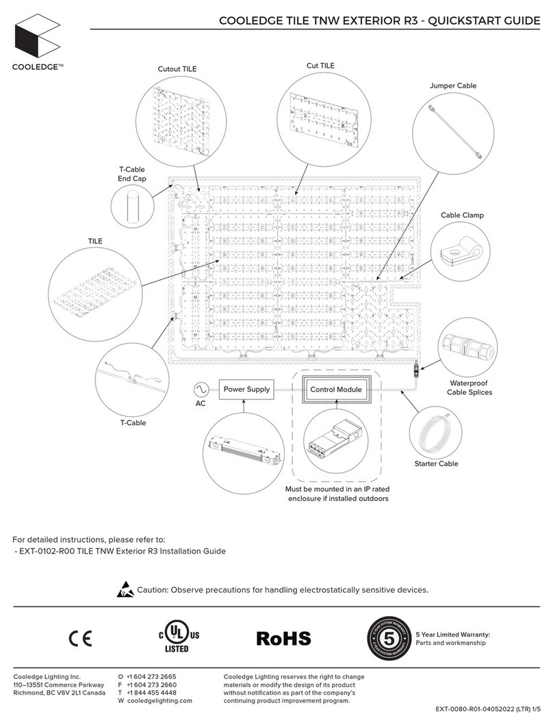
Cooledge
Cooledge TILE TNW EXTERIOR R3 quick start guide

Beamz
Beamz BMS50 user manual

Larson Electronics
Larson Electronics LEDHWP-900-DNMS instruction manual

Pahlen
Pahlen MiniMaster user manual
Vision & Control
Vision & Control LDLF30x180-G525/UDC Instructions for use
IKEA
IKEA LEDBERG Important safety instructions

Deep Blue
Deep Blue BlueFox Touch installation manual

Theralux
Theralux Water Management System Advanced user's manual
Vision & Control
Vision & Control TZB28-B450-P-SL Instructions for use

Gear4music
Gear4music SOL-70S user manual
Iluminarc
Iluminarc IP Series user manual
Amerlux
Amerlux GRUV 1.5” installation instructions

