ROBBE Super Star 3113 User manual

Montage- und
Bedienungsanleitung
Assembly and operating
instructions
Notice de montage et
d´utilisation
Super Star
No. 3113

Super Star
2
Bauanleitung, Assembly instructions, Notice de montage
3113
No.
Technische Daten
Spannweite: ca. 1200 mm
Gesamtlänge: ca. 970 mm
Gesamtflächeninhalt: ca. 27 dm2
Fluggewicht: ab 1200 g
Gesamtflächenbelastung: ab 44 g/dm2
Nicht enthaltenes Zubehör siehe Beilageblatt
Werkzeuge siehe robbe Hauptkatalog
Allgemeine Hinweise für den Bauablauf
Die Nummerierung entspricht im wesentlichen der Reihenfolge
des Bauablaufs, wobei die Nummer vor dem Punkt die
Baustufe, die Nummer hinter dem Punkt das betreffende
Bauteil angibt.
Verschaffen Sie sich in Verbindung mit den Abbildungen und
Kurztexten, sowie der Stückliste einen Überblick über die
jeweiligen Bauschritte.
Richtungsangaben, wie z. Bsp. „rechts“ sind in Flugrichtung
zu sehen.
Besondere Hinweise zu dem Werkstoff ARCEL
Der Super Star ist aus dem schlagzähen Formschaum ARCEL
gefertigt.
Dies bedeutet keine größeren Probleme beim Bau des
Modells, jedoch müssen beim Kleben und der
Oberflächenbehandlung einige werkstofftypische Eigenheiten
beachtet werden.
Verklebungen
Klebearbeiten an ARCEL-Formschaumteilen nur mit Robbe-
Speed-Sekundenkleber Typ 2 ausführen. Zum Aushärten der
Klebestellen Activatorspray verwenden.
Zum Verkleben von Metall- oder Kunststoffteilen mit
Formschaum ausschließlich Epoxy verwenden.
Hinweis zur Stückliste: n. e. = nicht enthalten
Hinweise zur Visiereinrichtung an den Tragflächen (Zierteil)
finden Sie auf Seite 23.
Caractéristiques techniques
Envergure : approx, 1200 mm
Longueur totale : approx, 970 mm
Surface alaire : approx, 27 dm2
Poids en ordre de vol : à partir de 1200 g
Charge alaire à la surface totale : à partir de 44 g/dm2
Accessoires non contenus, cf. feuillet joint
Outillage, reportez-vous au catalogue général robbe
Recommandations générales concernant la construction du
modèle
La numérotation des pièces correspond généralement à leur
ordre d’intervention dans la construction du modèle, le
numéro avant le point représentant le stade de montage en
cours et le numéro après le point constituant le la désignation
de la pièces elle-même.
Avant d’entreprendre l’assemblage du modèle, à l’aide des
schémas et des textes explicatifs, constituez-vous une vue
d’ensemble sur les stades de montage.
Les indications directionnelles telles que „gauche“ et „
droite“ sont à considérer dans le sens du vol de l’appareil.
Consignes spécifiques concernant le matériau de construc-
tion ARCEL
Le modèle Super Star est composé d’une mousse plastique
formée ARCEL.
Cela signifie que sa construction ne représente guère de prob-
lèmes, toutefois, pour le collage de ce matériau et pour le
traitement de surface il faut tenir compte des spécificités de ce
matériau.
Collages
N’effectuer de collage des pièces en mousse moulée ARCEL
qu’avec de la colle cyanoacrylate Robbe-Speed type 2. Pour
accélérer le séchage des emplacements collés, utilisez un
activateur en bombe.
Pour coller des éléments en métal ou en plastique avec le
matériau ARCEL, n’utilisez que de la colle à base époxyde.
Indications concernant la liste des pièces :
n. c. = non contenu dans la boîte de construction
Pour les indications concernant le dispositif d’identification de
l’assiette sur l’aile (élément de décoration, voyez la page 23.
Specification
Wingspan: approx. 1200 mm
Overall length: approx. 970 mm
Total surface area: approx. 27 dm2
All-up weight: approx. 1200 g
Total surface area loading: approx. 44 g / dm2
See separate sheet for accessories not included in the kit.
See the main robbe catalogue for details of tools.
Sequence of assembly
In general terms the numbering of the kit components reflects
the sequence of assembly; the number before the point indi-
cates the Stage of construction, the number after the point the
individual component.
To gain a clear idea how the model goes together, please study
the illustrations and brief instructions, referring to the Parts
Lists at the same time.
Directions such as “right-hand” are as seen from the tail of
the model looking forward.
Working with ARCEL components
The primary components of the Super Star are moulded in
ARCEL, which is a tough, resilient foam.
This presents no major problems during construction of the
model, but you must take certain characteristics of the mate-
rial into account when gluing joints and finishing the surfaces.
Glued joints
Use only Robbe Speed Type 2 cyano-acrylate for all joints
involving the moulded ARCEL foam parts. Use Activator spray
to accelerate curing.
Epoxy should be used for all joints between the moulded foam
parts and metal and plastic components.
Parts lists: N.I. = not included
Wingtip sighting frames (dummy fittings): see page 23.

Super Star
3
Bauanleitung, Assembly instructions, Notice de montage
3113
No.
Hinweise zur Fernsteuerung
Als Fernsteuerung benötigen Sie eine Anlage ab 4 Kanälen
und 4 Servos sowie einen elektronischen Fahrtregler mit BEC
- Funktion.
Sollte eine andere, als die von uns vorgeschlagene Steuerung
verwendet werden, können Sie sich nach dem Einbauschema
richten. Maßdifferenzen sind von Ihnen selbst auszugleichen.
Zur Inbetriebnahme immer den Gasknüppel in Stellung „Motor
aus“ bringen, den Sender einschalten. Erst dann den Akku
anschließen.
Zum Ausschalten immer die Verbindung Akku - Motorregler
trennen, erst dann den Sender ausschalten.
Baustufe 1, Tragfläche
Nr. Bezeichnung, Maße in mm Stück
1.1 Abdeckleisten 2 x 10 x 500 4
1.2 Tragflächenhälfte 2
1.3 Zunge 2
1.4 Zungenkasten 1
1.5 Dübel Ø 8 x 80 1
1.6 Querruderservo 2 n.e.
1.7 Verlängerungskabel 2 n.e.
1.8 Servohebel 2 bei 1.6
1.9 Dekorstreifen, weiß 4
1.10 Ruderhorn 2
1.11 Z-Gestänge Ø 1 x 45 2
1.12 Gestängekupplung 2
Indications concernant l’ensemble de radiocommande
Comme ensemble de radiocommande pour piloter l’appareil
vous devez disposer d’un ensemble d’au moins 4 voies et de
4 servos et d’un variateur électronique avec système d’ali-
mentation direct du récepteur BEC.
Si vous utilisez un autre ensemble de radiocommande que
celui que nous préconisons, reportez-vous aux schémas d’im-
plantation. À vous d’ajuster les cotes différentes.
Pour la mise en service, disposez systématiquement le
manche des gaz sur „moteur arrêté“ avant de mettre l’émet-
teur en marche. Ensuite seulement, raccordez l’accu d’alimen-
tation du moteur.
En fin de séance de pilotage, désolidarisez toujours d’abord
l’accu du variateur du moteur avant de couper l’émetteur.
Stade de montage 1, l’aile
N° désignation, cotes en mm nbre de pièces
1.1 baguettes de recouvrement 4
2 x 10 x 500
1.2 demi-aile 2
1.3 languette 2
1.4 coffret de languette 1
1.5 cheville Ø 8 x 80 1
1.6 servo d’aileron 2 n.c.
1.7 cordon-rallonge 2 n.c.
1.8 palonnier de servo 2 avec 1.6
1.9 bandes décoratives, blanche 4
1.10 guignol 2
1.11 tringle en Z Ø 1 x 45 2
1.12 accouplement de tringle 2
The radio control system
To control the model you will need a radio control system with
at least four channels, four servos and an electronic speed
controller with BEC function.
If you wish to use a radio control system other than the one we
recommend, you can still base your installation on the
arrangement shown. However, you may have to make
allowance for minor differences in component sizes.
Always check that the throttle stick is at the “motor stopped”
position before switching on the RC system transmitter. Do not
connect the flight battery until you have done this.
Always disconnect the flight battery from the speed controller
before you switch off the transmitter.
Stage 1, the wing
No. Description, size in mm No. off
1.1 Spar cap, 2 x 10 x 500 4
1.2 Wing panel 2
1.3 Wing joiner tongue 2
1.4 Joiner tongue box 1
1.5 Wing joiner retaining dowel, 8 Ø x 80 1
1.6 Aileron servo 2 N.I.
1.7 Extension lead 2 N.I.
1.8 Servo output lever 2 With 1.6
1.9 Trim stripe, white 4
1.10 Aileron horn 2
1.11 Pre-formed pushrod, 1 Ø x 45 2
1.12 Pushrod connector 2
-Die Abdeckleisten 1.1 in die
Tragflächenhälften 1.2 oben und unten
einpassen und mit Speed-Kleber ein-
kleben. Abdeckleisten durch Über-
schleifen dem Profilverlauf anpassen.
- Trial-fit the spar caps 1.1 in the wing
panels 1.2 top and bottom, and glue
them in place using cyano. Sand the
strips back flush with the wing section.
-Ajuster les baguettes de recouvrement
1.1 dans les demi-ailes 1.2 en haut et
en bas et les coller avec de la colle
cyanoacrylate. Ajuster les baguettes
de recouvrement en ponçant les pas-
sages de profil.
11.1
1.2
1.2
1.1

Super Star
4
Bauanleitung, Assembly instructions, Notice de montage
3113
No.
- Die Zungen 1.3 in den Zungenkasten
1.4 einschieben und mit dem Dübel 1.5
arretieren.
- Beidseitig eine Markierungslinie „M 1“
ziehen.
- Die korrekte Position der
Tragflächenhälften ergibt sich durch
die waagrecht verlaufende Oberkante
der Zungen 1.3. X re = X li.
- Oberkanten jeweils markieren - “M 2”.
- Die Zungen 1.3 unter Zugabe von
Epoxy in die Tragflächenhälften schie-
ben. Darauf achten, dass sich die
Schächte für die Querruderservos 1.6
jeweils unten befinden.
- Die Markierungslinie „M 1“ muss sich
mit der Profilwurzel decken.
- Glisser les languettes 1.3 dans le cof-
fret de languette 1.4 et les fixer avec la
cheville 1.5.
- De chaque côté, tracer une ligne de
repérage „M 1“.
- La position correcte des demi-ailes est
déterminée par l’alignement horizontal
de l’arête supérieure des languettes
1.3. X droite = X gauche.
- Repérer systématiquement les arêtes
supérieures - “M 2”.
- Glisser les languettes 1.3 dans les
demi-ailes après les avoir enduites de
colle époxy.
Veiller à ce que les logements des
servo d’ailerons 1.6 se trouvent
chaque fois en bas.
- La ligne de repérage „M 1“ doit corre-
spondre au profilé de la nervure d’em-
planture.
- Fit the joiner tongues 1.3 in the joiner
tongue box 1.4 and insert the dowel
1.5 to retain them.
- Draw a line “M 1” on the joiner tongues
on both sides of the tongue box as
shown.
- The position of the wing panels is cor-
rect when the top edge of the tongues
1.3 is horizontal: X right = X left.
- Mark the top edges of the joiner
tongues and the tongue box “M 2” as
shown.
- Epoxy the tongues 1.3 in the wing pan-
els; note that the wells for the aileron
servos 1.6 must be on the underside
of the wings.
- The marked lines “M 1” must be flush
with the root of the wing panels as
shown.
4
3
2
1.3 1.4
5
1.3
“M 1”
“M 1”
“M 1”
“M 1”
1.3
“M 2”
“M 2”
“M 2”
1.5
1.5
X li X re

Super Star
5
Bauanleitung, Assembly instructions, Notice de montage
3113
No.
- Querruderservos 1.6 mit
Verlängerungskabeln 1.7 versehen.
Servo mit der Fernsteuerung in
Neutralstellung bringen. Servohebel
1.8 beschneiden und montieren.
- Servos mit Epoxy in die Servoschächte
kleben. Verlängerungskabel in die
Kabelkanäle drücken.
-Die weißen Dekorstreifen 1.9 über die
unteren Abdeckleisten und die
Kabelkanäle kleben.
-Dekorstreifen 1.9 im Wurzelbereich an
der Stufe beschneiden.
- Munir le servo d’ailerons 1.6 des cor-
dons-rallonges 1.7.
Amener le servo à l’aide de l’ensemble
de radiocommande en position neutre.
Couper le palonnier de servo 1.8 et le
monter.
- Coller les servos avec de la colle époxy
dans les logements de servo. Glisser
les cordons-rallonges dans les con-
duits de cordon.
-Coller les bandes décoratives blanch-
es 1.9 les baguettes de recouvrement
du bas et les conduits de cordon.
-Couper les bandes décoratives 1.9
dans la zone de l’emplanture au niveau
de la transition.
- Connect the aileron servos 1.6 to the
extension leads 1.7. Set the servos to
neutral from the transmitter. Cut down
the servo output arms 1.8 as shown
and fit them on the servos.
- Locate the servo wells in the wing pan-
els, and glue the aileron servos in
them. Press the extension leads into
the cable ducts.
-Apply the white trim stripes 1.9 over
the bottom spar caps and the cable
ducts.
-Cut off the excess trim stripe material
1.9 flush with the step at the wing root.
6
7
8
1.7
1.8
1.9
1.6
9
1.8
1.9
1.9
Super Star
6
Bauanleitung, Assembly instructions, Notice de montage
3113
No.
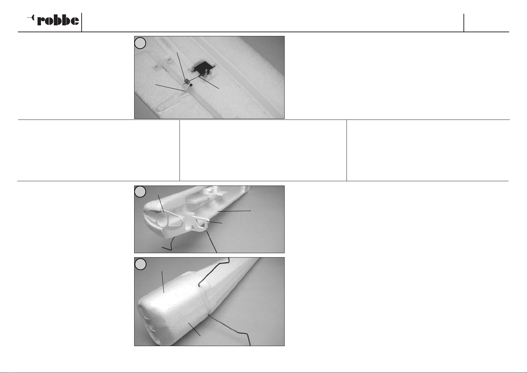
- Die äußeren Bohrungen der
Ruderhörner 1.10 auf 2 mm aufbohren.
Z-Gestänge 1.11 in den Servos ein-
hängen. Ruderhörner in die Querruder
einkleben. Querruder in Mittelstellung
bringen und mit den
Gestängekupplungen 1.12 an den
Ruderhörnern drehbar anschließen.
Schrauben mit Loctite sichern.
- Porter les alésages extérieurs des
guignols 1.10 à 2 mm de diamètre.
Accrocher les tringles en Z 1.11 dans
les servos. Coller les guignols dans les
ailerons. Amener les ailerons en posi-
tion médiane et les raccorder aux guig-
nols à l’aide des accouplements de
tringle 1.12 de manière qu’ils puissent
pivoter en souplesse.
Bloquer les vis avec du Loctite.
- Drill out the outer holes in the aileron
horns 1.10 to 2 mm Ø. Connect the
pre-formed pushrods 1.11 to the servo
output arms. Glue the horns in the
ailerons. Set the ailerons to neutral
(centre) and connect the pushrods to
the horns using the pushrod connec-
tors 1.12. Ensure that they swivel
smoothly, then secure each retaining
screw with a drop of Loctite (thread-
lock fluid).
2.1
2.2
10
11
Baustufe 2, der Rumpf
Nr. Bezeichnung, Maße in mm Stück
2.1 Kopfspant 1
2.2 Fahrwerk 1
2.3 Rumpfhalbschale rechts 1
2.4 Rumpfhalbschale links 1
Stage 2, the fuselage
No. Description No. off
2.1 Nose bulkhead 1
2.2 Undercarriage 1
2.3 Right-hand fuselage shell 1
2.4 Left-hand fuselage shell 1
Stade de montage 2, le fuselage
N° désignation, cotes en mm nbre de pièces
2.1 couple avant 1
2.2 atterrisseur 1
2.3 demi-coque de fuselage droite 1
2.4 demi-coque de fuselage gauche 1
-Den Kopfspant 2.1 und das Fahrwerk
2.2 in die rechte Rumpfhalbschale 2.3
einkleben.
-Die linke Rumpfhalbschale 2.4 probe-
weise aufsetzen, um ihren genauen
Sitz zu prüfen.
- Glue the nose bulkhead 2.1 and the
undercarriage 2.2 in the right-hand
fuselage shell 2.3.
- Offer up the left-hand fuselage shell
2.4 and check that it fits snugly
against the right-hand shell.
- Coller le couple avant 2.1 et l’atterris-
seur 2.2 dans la demi-coque droite de
fuselage 2.3.
-Mettre la demi-coque gauche de fuse-
lage 2.4 en place à titre d’essai afin de
contrôler son assise avec précision.
12
1.11
1.10
1.12
2.3
2.3
2.4
Super Star
7
Bauanleitung, Assembly instructions, Notice de montage
3113
No.
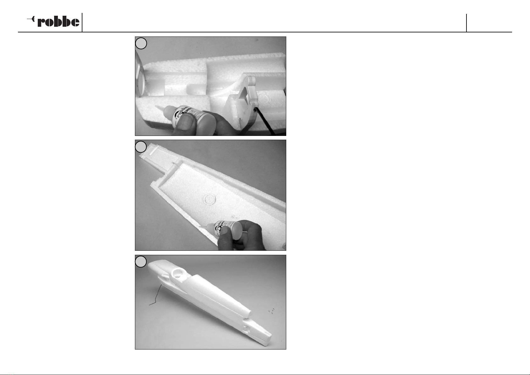
- Die Klebeflächen der rechten
Rumpfhalbschale und der Spanten mit
Speed-Kleber versehen.
- Linke Rumpfhalbschale aufsetzen und
so ausrichten, dass die Schalen run-
dum deckungsgleich aufeinanderlie-
gen. Das Aushärten des Klebers mit
Aktivatorspray beschleunigen.
- Munir les surfaces de collage de la
demi-coque droite de fuselage et des
couples de colle cyanoacrylate.
- Mettre la demi-coque gauche de fuse-
lage en place et l’aligner de telle sorte
que les coques s’ajustent parfaitement
tout autour. Accélérer le durcissement
de la colle en utilisant un activateur en
bombe.
- Apply cyano to the joint surfaces of the
right-hand fuselage shell and formers.
- Place the two fuselage shells together,
and check immediately that they line
up correctly and make good contact all
round. Apply Activator spray to accel-
erate the cure.
14
15
13
Super Star
8
Bauanleitung, Assembly instructions, Notice de montage
3113
No.
- Den Zungenkasten 1.4 in den Rumpf
schieben, mittig ausrichten und verkle-
ben. Die Markierung “M 2” muß sich
oben befinden.
- Die Tragflächenhälften probeweise
ansetzen, dabei die Kabel der
Querruderservos nach innen führen.
- Tragflächen mit dem eingeschobenen
Dübel 1.5 sichern.
- Glisser le coffret de languette 1.4 dans
le fuselage, le centrer parfaitement et
le coller. Le repère “M 2” doit se trou-
ver en haut.
-Mettre les demi-ailes en place à titre
d’essai en agençant simultanément les
cordons des servo d’ailerons vers l’in-
térieur.
-Fixer les demi-ailes en mettant la
cheville 1.5 en place.
- Slide the joiner tongue box 1.4 into the
fuselage, set it central and glue it in
place. Note that the marked line “M 2”
must be at the top.
- Slide the wing joiner tongues into the
tongue box, and push the wing panels
against the fuselage, running the
aileron servo leads into the fuselage as
you do so.
- Push the retaining dowel 1.5 into place
to secure the wings.
17
16
18
1.4
“M 2”
1.5

Super Star
9
Bauanleitung, Assembly instructions, Notice de montage
3113
No.
20
19
21
Baustufe 3, die Leitwerke
Nr. Bezeichnung, Maße in mm Stück
3.1 Höhenruderservo 1 n.e.
3.2 Servo-Verlängerungskabel 2 n.e.
3.3 Servohebel 2 bei 3.1, 3.4
3.4 Seitenruderservo 1 n.e.
3.5 Höhenleitwerk mit Ruder 1
3.6 Seitenleitwerk mit Ruder 1
3.7 Ruderhorn 2
3.8 Z-Gestänge, Ø 1 x 10⁵ 1 Seitenruder
3.9 Z-Gestänge, Ø 1 x 80 1 Höhenruder
3.10 Gestängekupplung 2
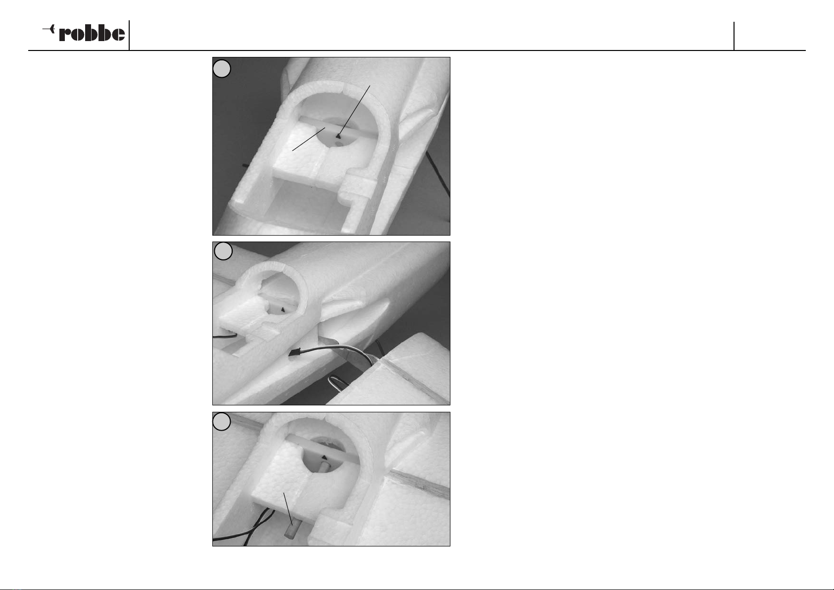
- Das Höhenruderservo 3.1 mit dem
Verlängerungskabel 3.2 versehen.
Servo mit der Fernsteuerung in
Neutralstellung bringen. Servohebel 3.3
wie zuvor beschneiden und montieren,
siehe Bild 6.
- Steckverbindung mit Klebeband
sichern. Verlängerungskabel in den
Rumpf führen.
- Servo unter Zugabe von Epoxy in den
Servoschacht setzen. Auf freigehenden
Servohebel achten.
- Auf die gleiche Weise das
Seitenruderservo 3.4 vorbereiten und
einbauen.
Stage 3, the tail panels
No. Description, size in mm No. off
3.1 Elevator servo 1 N.I.
3.2 Servo extension lead 2 N.I.
3.3 Servo output lever 2 With 3.1 / 3.4
3.4 Rudder servo 1 N.I.
3.5 Tailplane and elevator 1
3.6 Fin and rudder 1
3.7 Horn 2
3.8 Pre-formed pushrod, 1 Ø x 105 1 Rudder
3.9 Pre-formed pushrod, 1 Ø x 80 1 Elevator
3.10 Pushrod connector 2
Stade de montage 3, les empennages
N° désignation, cotes en mm nbre de pièces
3.1 servo de la gouverne de prof. 1 n.c.
3.2 cordon-rallonge de servo 2 n.c.
3.3 palonnier de servo, avec 3.1, 3.4 2
3.4 servo de la gouverne de direct. 1 n.c.
3.5 stabilisateur avec gouverne 1
3.6 dérive avec gouverne 1
3.7 guignol 2
3.8 tringle en Z, Ø 1 x 10⁵ 1 direction
3.9 tringle en Z, Ø 1 x 80 1 profondeur
3.10 accouplement de tringle 2
- Connect the elevator servo 3.1 to the
extension lead 3.2, and set the servo
to neutral from the transmitter. Cut
down the servo output lever 3.3 as
described earlier, and mount it on the
servo: see Fig. 6.
- Wrap tape round the extension lead
connection to secure it, then run the
extension lead through the fuselage
towards the nose.
- Epoxy the elevator servo in the servo
well. Check that the servo output arm
is not obstructed in its movement.
- Prepare the rudder servo 3.4 in the
same way, and install it in the appro-
priate recess in the fuselage.
- Munir le servo de la gouverne de pro-
fondeur 3.1 du cordon-rallonge 3.2.
Amener le servo en position neutre à
l’aide de l’ensemble de radiocom-
mande. Comme indiqué précédem-
ment, couper le palonnier de servo 3.3
et le monter, cf. fig. 6.
- Fixer le connecteur à l’aide d’un
morceau de ruban adhésif. Engager le
cordon-rallonge dans le fuselage.
- Installer le servo dans le logement de
servo après y avoir appliqué de la colle
époxy. Veiller à ce que le palonnier de
servo ne soit pas gêné dans son mou-
vement.
- De la même manière, préparer le servo
de la gouverne de direction 3.4 et le
mettre en place.
3.1
3.3
3.4
3.2
3.3
Super Star
10
Bauanleitung, Assembly instructions, Notice de montage
3113
No.
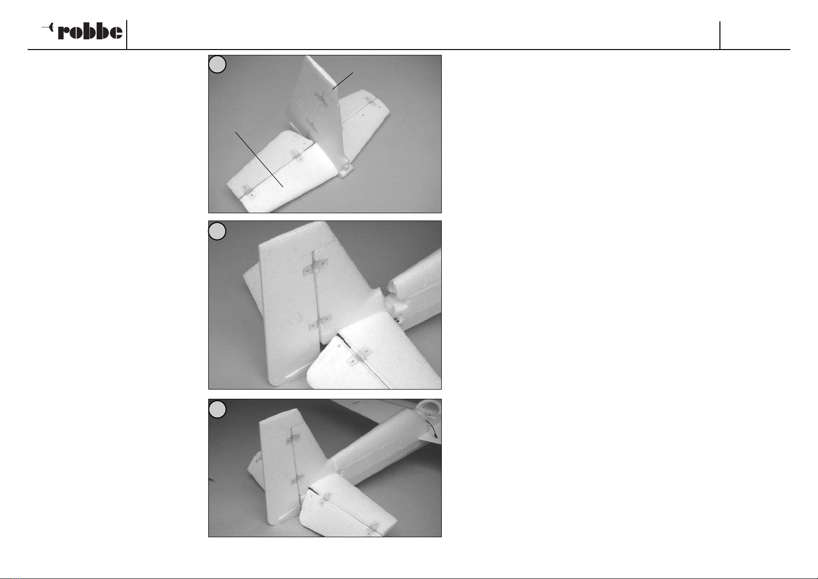
- Höhenleitwerk 3.5 und Seitenleitwerk
3.6 genau rechtwinklig zueinander ver-
kleben.
- Leitwerkseinheit auf den Rumpf set-
zen. Die Tragflächen müssen zum fol-
genden Ausrichten montiert sein.
- Klebeflächen mit Speed-Kleber verse-
hen, Einheit aufschieben.
- Coller le stabilisateur 3.5 et la dérive
3.6 exactement à angle droit l’un par
rapport à l’autre.
- Installer les empennages sur le fuse-
lage. Installer les demi-ailes sur le
fuselage pour les travaux de mise au
point décrits ci-dessous.
- Munir les surfaces de collage de colle
cyanoacrylate, mettre les empennages
en place.
- Glue the tailplane 3.5 and fin 3.6
together; check that they are exactly at
right-angles to each other.
- Place the tail assembly on the fuse-
lage. The next step is to glue and align
the tail panels, and this requires that
the wings be fitted to the fuselage.
- Apply cyano to the tail joint surfaces
and place the assembly in position on
the tail end of the fuselage.
23
22
24
3.5
3.6
Super Star
11
Bauanleitung, Assembly instructions, Notice de montage
3113
No.
3.10
3.7
26
25
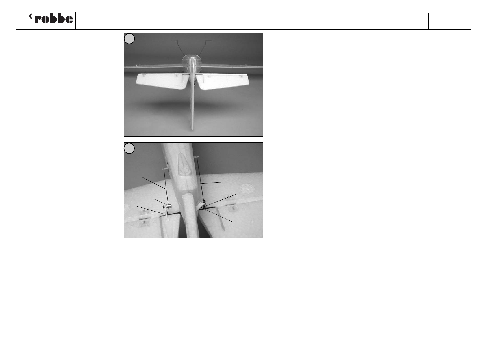
- Leitwerkseinheit nach Sichtprüfung zu
den Tragflächen ausrichten. Aushärten
mit Aktivatorspray beschleunigen.
-Die äußeren Bohrungen der
Ruderhörner 3.7 auf 2 mm aufbohren.
Z-Gestänge 3.8, 3.9 in den Servos ein-
hängen. Ruderhörner in die Ruder ein-
kleben. Ruder in Mittelstellung bringen
und mit den Gestängekupplungen
3.10 an den Ruderhörnern drehbar
anschließen. Schrauben mit Loctite
sichern.
- Align the tailplane with the wings by
sighting along the fuselage as shown.
Apply Activator spray to accelerate
the cure.
- Drill out the outer holes in the horns
3.7 to 2 mm Ø. Connect the pre-
formed pushrods 3.8 and 3.9 to the
servos. Glue the horns in the rudder
and elevator as shown. Set the control
surfaces to centre, and connect the
pushrods to the horns using the
pushrod connectors 3.10. Tighten the
retaining screws and secure each one
with a drop of Loctite.
- Pour effectuer un contrôle visuel,
ajuster les empennages par rapport
aux demi-ailes. Accélérer le durcisse-
ment de la colle en y projetant de l’ac-
tivateur en bombe.
- Porter les alésages extérieurs des
guignols 3.7 à 2 mm de diamètre.
Accrocher les tringles en Z 3.8, 3.9
dans les servos. Coller les guignols
dans les gouvernes. Amener les gou-
vernes en position médiane et avec
les accouplements de tringle 3.10 les
raccorder aux guignols de manière
qu’elles puissent effectuer leurs
débattements en souplesse. Bloquer
les vis avec du Loctite.
Baustufe 4, das Fahrwerk
Nr. Bezeichnung, Maße in mm Stück
4.1 Spornfahrwerk 1
4.2 Mitnehmerdübel, Ø 2 x 30 1
4.3 Gummiring 1
4.4 Fahrwerksverkleidung innen 2
4.5 Stellring Ø 3,2 x 8 4
4.6 Unterlegscheibe, Ø 3,2 x Ø 7 x 1 6
4.7 Rad 2
4.8 Fahrweksverkleidung außen 2
Stage 4, the undercarriage
No. Description, size in mm No. off
4.1 Tailwheel unit 1
4.2 Driver rod, 2 Ø x 30 1
4.3 Rubber band 1
4.4 Wheel spat, inner shell 2
4.5 Collet, 3.2 Ø x 8 4
4.6 Washer, 3.2 Ø x 7 Ø x 1 6
4.7 Wheel 2
4.8 Wheel spat, outer shell 2
Stade de montage 4, l’atterrisseur
N° désignation, cotes en mm nbre de pièces
4.1 éperon d’atterrisseur arrière 1
4.2 cheville d’entraînement, Ø 2 x 30 1
4.3 élastique 1
4.4 carénage d’atterrisseur intérieur 2
4.5 bague d’arrêt Ø 3,2 x 8 4
4.6 rondelle-entretoise, Ø 3,2 x Ø 7 x 1 6
4.7 roue 2
4.8 carénage d’atterrisseur extérieur 2
3.7
3.9 3.8
3.10
Super Star
12
Bauanleitung, Assembly instructions, Notice de montage
3113
No.
4.3
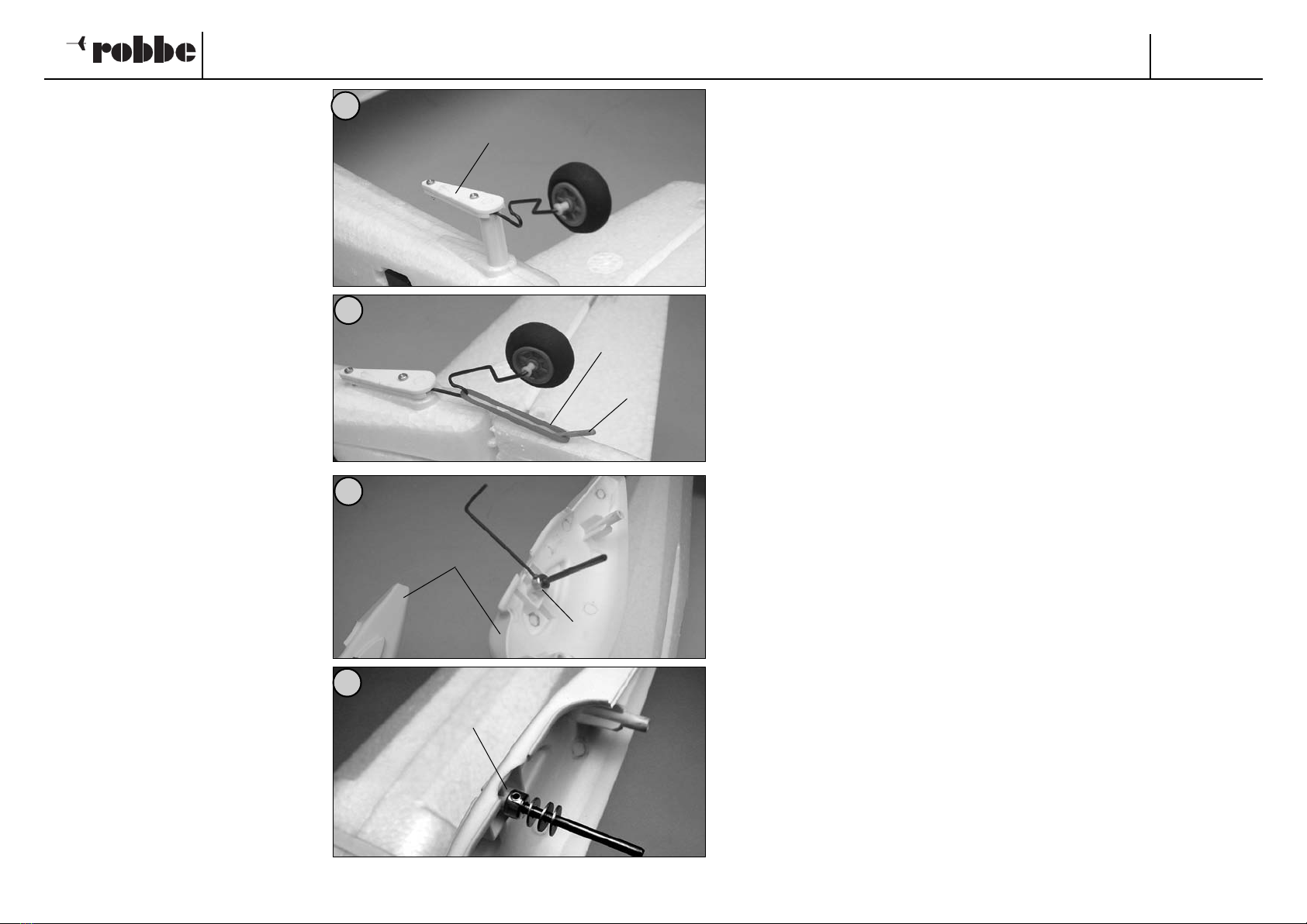
- Das Spornfahrwerk 4.1 einkleben.
-Seitenruder mit einer schräg verlau-
fenden 1,5 mm Bohrung versehen und
den Mitnehmerdübel 4.2 einkleben.
- Gummiring 4.3 einhängen.
- Die inneren Halbschalen 4.4 der
Fahrwerksverkleidung aufschieben
und mit je einem Stellring 4.5 sichern.
- Je 3 U-Scheiben 4.6 aufschieben.
- Glue the tailwheel unit 4.1 in the fuse-
lage as shown.
- Pierce a 1.5 mm Ø hole in the rudder
at an angle, as shown in the picture,
and glue the driver rod 4.2 into it.
- Connect the rubber band 4.3 between
the driver rod and the tailwheel unit.
- Fit the inner spat shells 4.4 on the
wheel axles and secure each with a
collet 4.5.
- Fit three washers 4.6 on each axle.
- Coller l’éperon d’atterrisseur arrière
4.1.
- Munir la gouverne de direction d’un
alésage de biais de 1,5 mm et coller la
cheville d’entraînement 4.2.
- Accrocher l’élastique 4.3.
- Mettre les demi-coques intérieures 4.4
des carénages d’atterrisseur en place
et les fixer systématiquement avec
une bague d’arrêt 4.5.
- Mettre chaque fois trois rondelles 4.6
en place.
4.2
29
30
28
27
4.4
4.5
4.6
4.1

Super Star
13
Bauanleitung, Assembly instructions, Notice de montage
3113
No.
- Räder 4.7 mit je einem weiteren
Stellring 4.5 leicht drehbar befestigen.
- Den Rand und die Zapfen der äußeren
Halbschalen 4.8 mit Speed-Kleber
versehen und Halbschalen aufsetzen.
- Fit the wheels 4.7 followed by a further
collet 4.5. Tighten the collet grub-
screws, and check that the wheels
rotate freely.
- Apply cyano to the flange and the lugs
of the outer spat shells 4.8, then posi-
tion them against the inner shells and
hold them while the glue sets.
- Fixer les roues 4.7 chaque fois avec
une autre bague d’arrêt 4.5 de
manière qu’elles puissent tourner en
souplesse.
-Munir le bord et les languettes des
demi-coques extérieures 4.8 de colle
cyanoacrylate et mettre les demi-
coques en place.
33
31
32
4.7
4.8
4.5

Super Star
14
Bauanleitung, Assembly instructions, Notice de montage
3113
No.
5.1
Baustufe 5, der Antrieb
Nr. Bezeichnung, Maße in mm Stück
5.1 Ritzel 1 n.e.
5.2 E-Motor 1 n.e.
5.3 Getriebeflansch 1 n.e.
5.4 Senkschraube 2 n.e.
5.5 Getriebe 1 n.e.
5.6 Entstörsatz 1 n.e.
5.7 Regler 1 n.e.
5.8 Steckverbindung 1 n.e.
5.9 Klettband 2
5.10 Schraube M 3 x 10 2
5.11 Zahnscheibe Ø 3,2 innen 2
5.12 Motorspant 1
5.13 Blechschraube Ø 2,9 x 9,5 4
5.14 U-Scheibe Ø 3,2 innen 4
5.15 Luftschraubenmitnehmer 1 n.e.
5.16 Madenschraube M 3 x 6 2 n.e.
5.17 Motorhaube 1
5.18 Spinner Ø 45 1 n.e.
5.19 Luftschraube 1 n.e.
5.20 Flugakku 1 n.e.
5.21 Steckverbindung 1 n.e.
5.22 Montageleiste 5 x 20 x 220 1
5.23 Klettband 2
Stage 5, the power system
No. Description, size in mm No. off
5.1 Pinion 1 N.I.
5.2 Electric motor 1 N.I.
5.3 Gearbox flange 1 N.I.
5.4 Countersunk screw 2 N.I.
5.5 Gearbox 1 N.I.
5.6 Suppressor set 1 N.I.
5.7 Speed controller 1 N.I.
5.8 Power connector set 1 N.I.
5.9 Velcro (hook-and-loop) tape 2
5.10 Screw, M3 x 10 2
5.11 Shakeproof washer, 3.2 I.D. 2
5.12 Motor bulkhead 1
5.13 Self-tapping screw, 2.9 Ø x 9.5 4
5.14 Washer, 3.2 I.D. 4
5.15 Propeller driver 1 N.I.
5.16 Grubscrew, M3 x 6 2 N.I.
5.17 Cowl 1
5.18 Spinner, 45 Ø 1 N.I.
5.19 Propeller 1 N.I.
5.20 Flight battery 1 N.I.
5.21 Power connector set 1 N.I.
5.22 Mounting rail, 5 x 20 x 220 1
5.23 Velcro tape 2
Stade de montage 5, l’entraînement
N° désignation, cotes en mm nbre de pièces
5.1 pignon 1 n.c.
5.2 moteur électrique 1 n.c.
5.3 bride d’engrenage 1 n.c.
5.4 vis à tête fraisée 2 n.c.
5.5 engrenage 1 n.c.
5.6 kit d’antiparasitage 1 n.c.
5.7 variateur 1 n.c.
5.8 connecteur 1 n.c.
5.9 bande Velcro 2
5.10 vis M 3 x 10 2
5.11 rondelle éventail Ø 3,2 intérieur 2
5.12 couple-moteur 1
5.13 vis autotaraudeuse Ø 2,9 x 9,5 4
5.14 rondelle Ø 3,2 intérieur 4
5.15 entraîneur d’hélice 1 n.c.
5.16 vis sans tête M 3 x 6 2 n.c.
5.17 capot-moteur 1
5.18 cône d’hélice Ø 45 1 n.c.
5.19 hélice 1 n.c.
5.20 accu d’alimentation du moteur 1 n.c.
5.21 connecteur 1 n.c.
5.22 baguette de montage 5 x 20 x 220 1
5.23 bande Velcro 2
-Ritzel 5.1 und Welle des Motors 5.2
entfetten, Ritzel aufkleben. Dazu den
Klebstoff verwenden, der dem
Getriebe beigefügt ist. Darauf achten,
dass kein Kleber in den Motor ein-
dringt.
- De-grease the pinion 5.1 and the out-
put shaft of the electric motor 5.2,
then glue the pinion on the shaft using
the adhesive supplied with the gear-
box. Take great care that no adhesive
gets inside the motor.
-Dégraisser le pignon 5.1 et l’arbre du
moteur 5.2, coller le pignon. Pour ce
faire, utiliser la colle fournie avec l’en-
grenage. Veiller à ce que la colle ne
s’introduise pas dans le moteur.
34 5.2

Super Star
15
Bauanleitung, Assembly instructions, Notice de montage
3113
No.
- Den Flansch 5.3 mit Senkschrauben
5.4 befestigen.
- Zahnräder des Getriebes 5.5 vor der
Montage fetten.
- Den Motor mit dem Entstörsatz 5.6
entstören, Schottky-Diode und
Motorkabel des Reglers 5.7 unter
Beachtung der Polung anlöten.
- Akkukabel des Reglers mit einer geeig-
neten Steckverbindung 5.8 versehen,
siehe Bild 40.
-Bei allen Arbeiten am Regler die
Anleitungen beachten, die dem Gerät
bzw. dem Entstörsatz beigefügt sind.
- Die Unterseite des Reglers mit einem
Stück Klettband (Flauschband) 5.9 ver-
sehen.
- Attach the gearbox flange 5.3 to the
motor using the countersunk screws
5.4.
- Grease the gears of the gearbox 5.5,
then screw it onto the gearbox flange.
-Attach the suppressor set capacitors
5.6 to the motor, and solder the
Schottky diode and the motor wires
(attached to the speed controller 5.7)
to the terminals, taking care to main-
tain correct polarity.
- Fit suitable connectors 5.8 to the bat-
tery wires attached to the speed con-
troller; see Fig. 40.
-Before you carry out any work involv-
ing the speed controller be sure to read
the instructions supplied with the unit
and the suppressor set.
- Stick a piece of Velcro tape (loop side)
5.9 to the underside of the speed con-
troller.
- Fixer la bride 5.3 avec les vis à tête
fraisé 5.4.
- Graisser les roues dentées de l’en-
grenage 5.5 avant de les mettre en
place.
-Antiparasiter le moteur à l’aide du kit
d’antiparasitage 5.6, souder la diode
Schottky et les brins du variateur 5.7 à
destination du moteur en veillant à
respecter les polarités.
- Munir le cordon de l’accu du variateur
d’un connecteur 5.8 approprié, cf. fig.
40.
- Pour tous les travaux concernant le
variateur tenir compte de la notice qui
l’accompagne de même que de celle
qui est jointe au kit d’antiparasitage.
-Munir le dessous du variateur d’un
morceau de bande Velcro (bande
pelucheuse) 5.9
35
37
36
5.3
5.4
38
5.5
5.7
5.9
5.6
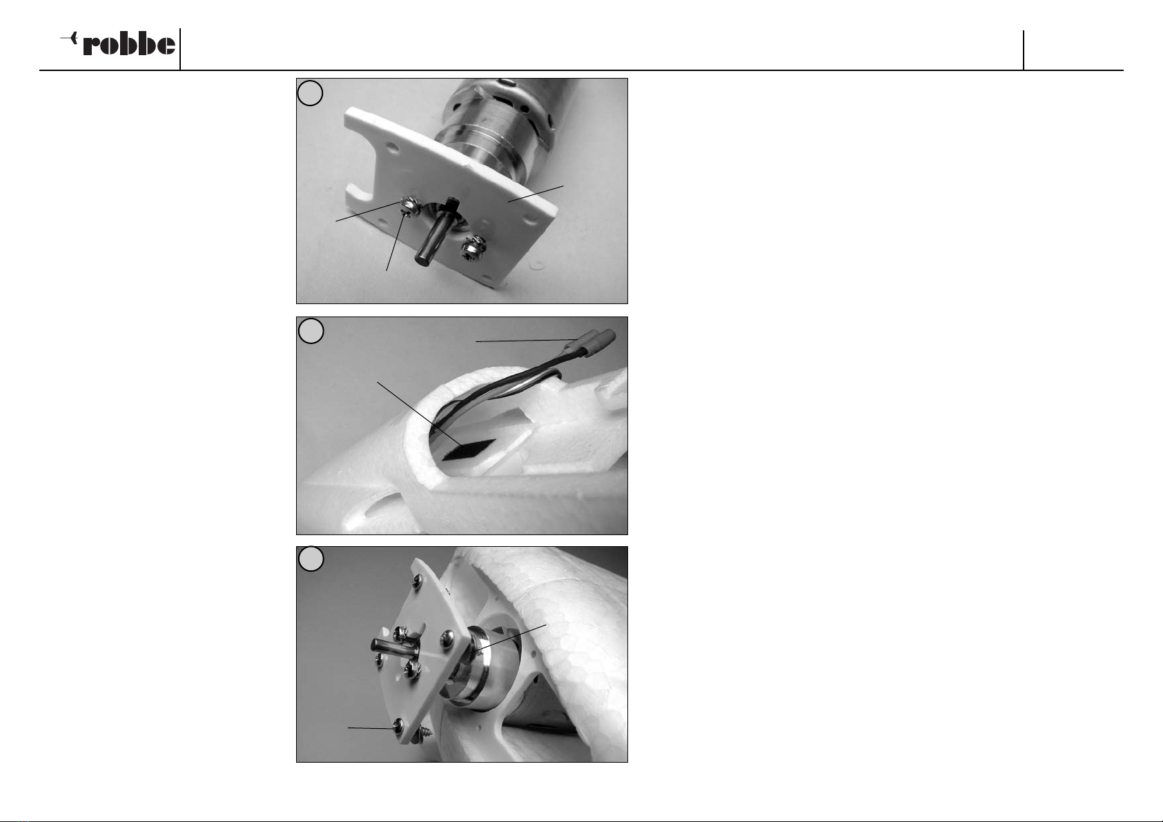
- Die Antriebseinheit mit Schrauben 5.10
und Zahnscheiben 5.11 am
Motorspant 5.12 montieren.
- Ein weiteres Stück Klettband 5.9
(Hakenband) für den Regler in den
Rumpf kleben.
- Regler und Kabel in den Rumpf führen.
Antrieb einsetzen.
- Die linken Schrauben 5.13 mit je 2 U-
Scheiben 5.14 zum Einstellen des
Rechtszugs versehen. Motorspant ver-
schrauben.
Super Star
16
Bauanleitung, Assembly instructions, Notice de montage
3113
No.
- Monter l’unité d’entraînement avec les
vis 5.10 et les rondelles éventail 5.11
sur le couple-moteur 5.12.
- Coller un autre morceau de bande
Velcro 5.9 (bande accrocheuse) pour le
variateur dans le fuselage.
- Agencer le variateur et son cordon
dans le fuselage.
Mettre l’entraînement en place.
- Munir les vis 5.13 de gauche de deux
rondelles-entretoises 5.14 chaque fois
afin d’établir l’angle d’anticouple.
Visser le couple-moteur.
- Mount the geared motor unit on the
motor bulkhead 5.12 using the screws
5.10 and the shakeproof washers 5.11.
- Stick another piece of Velcro tape
(hook side) 5.9 in the fuselage where
the speed controller is to be mounted.
- Install the speed controller and leads in
the fuselage. Fit the motor assembly in
the fuselage.
- Fit two washers 5.14 on each of the
left-hand mounting screws 5.13 to set
the correct right sidethrust. Screw the
motor bulkhead in place.
41
40
39
5.12
5.10
5.11
5.13
5.14
5.9
5.8

Super Star
17
Bauanleitung, Assembly instructions, Notice de montage
3113
No.
- Bei der Montage des
Luftschraubenmitnehmers 5.15 mit
den Madenschrauben 5.16 ausrei-
chenden Abstand zu den Schrauben
5.10 einhalten.
- Den Rand der Motorhaube 5.17 durch
Beschneiden anpassen. Motorhaube
aufsetzen und oben und unten mit
Klebebandstreifen fixieren.
- Den Spinner 5.18 an die vorgesehene
Luftschraube 5.19 anpassen.
Luftschraube und Spinner montieren.
-Am Akku 5.20 eine Steckverbindung
5.21 zum Anschluß am Regler anbrin-
gen - Polung beachten.
-Die Montageleiste 5.22 mit Klebeband
am Akku 5.20 befestigen und mit
einem Stück Klettband 5.23 versehen.
- Fit the propeller driver 5.15 on the
gearbox output shaft and tighten the
grubscrews 5.16 to secure it. Check
that the driver does not foul the
screws 5.10.
- Trim the edges of the cowl 5.17 to
obtain an accurate fit. Place the cowl
on the model and secure it with strips
of adhesive tape top and bottom.
- Trim the notches in the spinner 5.18 to
clear the blades of the propeller 5.19.
Fit the propeller and spinner on the
propeller driver.
-Attach matching connectors 5.21 to
the flight battery 5.20 so that it can be
connected to the speed controller,
again taking care to maintain correct
polarity.
- Fix the mounting rail 5.22 to the flight
battery 5.20 using adhesive tape, and
stick a piece of Velcro tape 5.23 to it
as shown.
- Lors du montage de l’entraîneur
d’hélices 5.15 avec les vis sans tête
5.16 veiller à préserver un écart suff-
isamment important par rapport aux
vis 5.10.
- Ajuster le bord du capot-moteur 5.17
en le découpant. Mettre le capot-
moteur en place et le fixer en haut et
en bas avec des morceaux de ruban
adhésif.
- Ajuster le cône d’hélice 5.18 à l’hélice
prévue 5.19. Monter l’hélice et le
d’hélice.
-Sur l’accu 5.20 installer un connecteur
5.21 pour permettre le raccordement
au variateur – observer les polarités.
- Fixer la baguette de montage 5.22
avec des morceaux de ruban adhésif à
l’accu 5.20 et y appliquer un morceau
de bande Velcro 5.23.
43
44
42
5.10
5.15
5.16
5.17
5.19
5.18
5.20
5.21
5.22
5.23
Super Star
18
Bauanleitung, Assembly instructions, Notice de montage
3113
No.
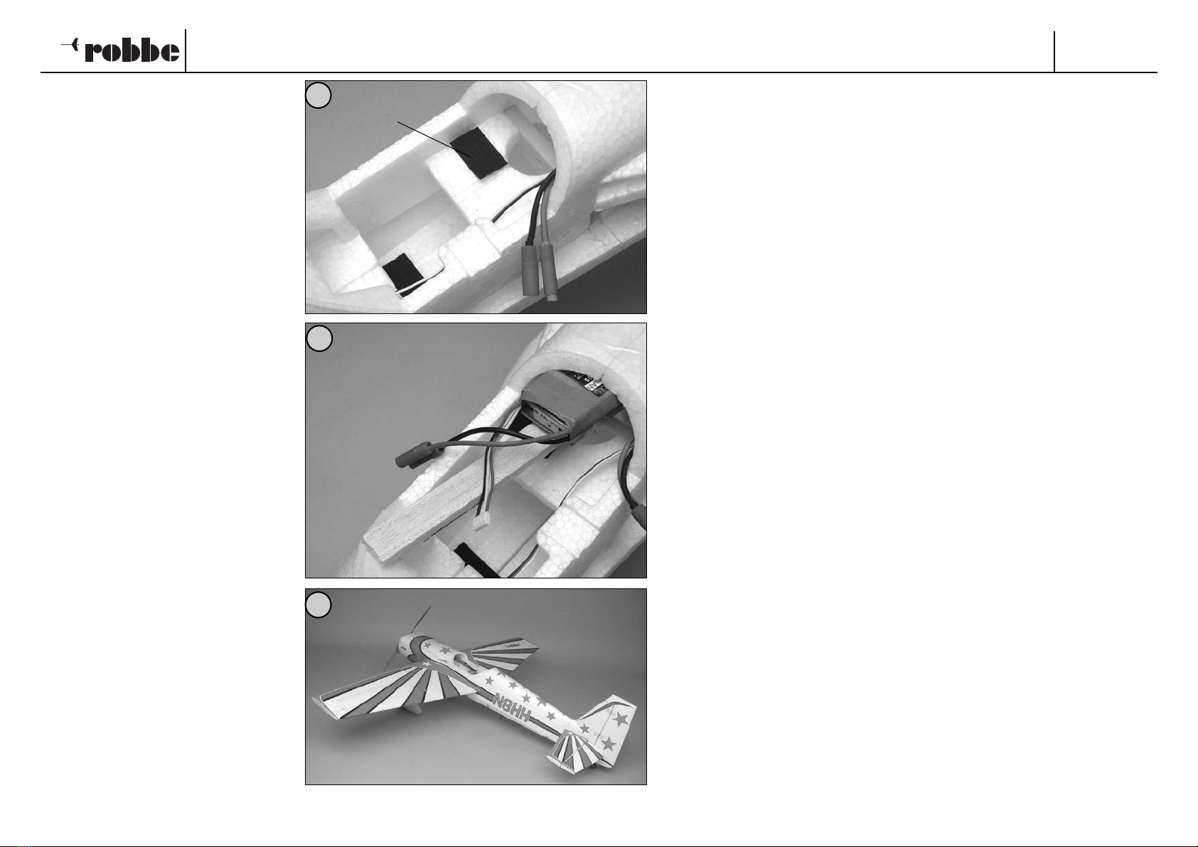
- Das Gegenstück 5.23 in den Rumpf
kleben.
- Akku einsetzen, nicht anschließen.
Stufe 6
Dekor und Oberflächenbehandlung
Dem Modell liegen verschiedenfarbige
Dekorbögen bei. Bleibt der Rumpf in der
Grundfarbe weiß, wird der Dekorbogen
mit den roten Zierstreifen verwendet.
Soll der Rumpf in der Grundfarbe rot
lackiert werden, steht der Bogen mit den
weißen Zierstreifen zur Verfügung. Die
Kartonagenabbildung zeigt die entspre-
chende Gestaltung in rot.
Das Tragflächendekor und das
Leitwerksdekor sind in beiden Fällen
gleich.
Zur Farbgebung von ARCEL können
robbe-rocolor ARCEL-Sprühlacke ver-
wendet werden. Keine anderen Farben
verwenden, da diese die Oberfläche
angreifen und zerstören können.
- Stick the mating piece of Velcro tape
5.23 in the fuselage as shown.
- Install the battery, but do not connect
it at this stage.
Stage 6
Applying the decals, surface finishing
The model is supplied complete with
two decal sheets of different colours. If
you intend to leave the fuselage in its
basic white colour, the decal sheet with
the red trim stripes should be applied. If
you prefer to paint the fuselage red over-
all, the sheet with the white trim stripes
is the one to use. The kit box illustration
shows the model finished in red.
The wing and tail decals are the same in
either case.
To colour the ARCEL components we
recommend robbe rocolor ARCEL spray
paints. Do not use any other type of
paint, as it might attack and melt the sur-
face.
-The decals should be applied to the
model section by section. Only cut out
one decal at a time.
-Remove rough edges from the leading
edge of the wing and tailplane panels.
- Coller la pièce antagoniste 5.23 dans
le fuselage.
- Mettre l’accu en place, ne pas le rac-
corder pour l’instant.
Stade de montage 6
Application des autocollants de décora-
tion et traitement de surface
Le modèle est livré avec des feuillets
d’autocollants multicolores. Si le fuselage
conserve sa couleur blanche de base
originale, utilisez le feuillet d’autocollants
de décoration avec la bande décorative
rouge.
Si le modèle est peint en rouge, appliquez
le feuillet d’autocollants muni de la bande
décorative blanche. Les illustrations figu-
rant sur le carton d’emballage représen-
tent l’agencement du décor en rouge.
La décoration de l’aile et des empen-
nages est la même dans les deux cas.
Pour appliquer une peinture sur les élé-
ments en ARCEL, utilisez les peintures en
bombe robbe-rocolor ARCEL. Ne pas
utiliser d’autres produits car ceux-ci sont
susceptibles d’attaquer la surface et de la
détruire.
-Appliquer les éléments de décoration
selon les indications fournies par les
illustrations de la boîte de construction
en procédant par étapes. Découper un
seul élément de décoration à la fois.
45
46
47
5.23

Super Star
19
Bauanleitung, Assembly instructions, Notice de montage
3113
No.
- Das Dekor gemäß den Abbildungen
abschnittweise aufbringen. Jeweils ein
Dekorteil ausschneiden.
- Nasenbereich von Tragfläche und
Höhenleitwerk entgraten.
- Zum Positionieren großer Dekorteile
die Trägerschicht an der Nasenleiste
ca. 5 cm abziehen und abschneiden.
Dekor ausrichten, ankleben und
Trägerfolie stückweise abziehen.
Dabei das Dekor faltenfrei aufreiben.
- Die Dekorteile haften erst schlüssig,
wenn sie mit einem Bügeleisen
erwärmt werden. Die Temperatur
dabei nahe von „Seide“ einstellen. Es
empfiehlt sich, sich an die richtige
Temperatur „heranzutasten“.
- To position the large decals we recom-
mend that you peel away the backing
film at the leading edge for a distance of
about 5 cm, and cut off that strip.
Position the decal carefully, holding the
exposed adhesive clear of the surface,
then rub it down onto the model. Peel off
the backing film gradually, working from
the attached area, and rubbing the decal
down as you go. If you use this method
and work carefully, the decals will soon
be applied without creases or bubbles.
- The decals only adhere really strongly
when heated gently using a film iron. Set
the iron temperature to “silk”. It is a good
idea to start with an even lower temper-
ature, then increase it gradually until the
decals adhere properly.
- Ébarber la zone du bord d’attaque des
demi-ailes et du stabilisateur.
- Pour positionner de plus grands élé-
ments de décoration, retirer le film
support au bord sur approximative-
ment 5 cm et le couper. Ajuster l’élé-
ment de décoration, l’appliquer et en
retirer le film progressivement.
Appliquer systématiquement l’élément
de décoration en supprimant les
bulles d’air. Les éléments de décora-
tion adhèrent définitivement lorsqu’on
les chauffe avec un fer à repasser.
Veiller à régler d’abord la température
du fer à repasser sur „soie“. Il est
recommandé, si nécessaire, de n’aug-
menter la température qu’avec une
„très légère“ progression.
Baustufe 7, Kabine, Endarbeiten
Nr. Bezeichnung, Maße in mm Stück
7.1 Empfänger 1 n.e.
7.2 Klettband 2
7.3 V-Kabel 1 n.e.
7.4 Kabine 1
7.5 Cockpit 1
7.6 Klettband 2
- Den Empfänger 7.1 mit
Klettbandstücken 7.2 im Rumpf plat-
zieren.
-Servos und Regler anschließen. Zum
Anschluss der Querruderservos ein V-
Kabel 7.3 verwenden.
-Den Rand an der Kabinenauflage mit
einem scharfen Messer entfernen.
48
49 7.1, 7.2
7.3
Stage 7, cabin, final work
No. Description, size in mm No. off
7.1 Receiver 1 N.I.
7.2 Velcro tape 2
7.3 Y-lead 1 N.I.
7.4 Canopy 1
7.5 Cockpit 1
7.6 Velcro tape 2
Stade de montage 7, la cabine, travaux de finition
N° désignation, cotes en mm nbre de pièces
7.1 récepteur 1 n.c.
7.2 bande Velcro 2
7.3 cordon Y 1 n.c.
7.4 cabine 1
7.5 cockpit 1
7.6 bande Velcro 2
-Install the receiver 7.1 in the fuselage
using two pieces of Velcro tape 7.2.
-Connect the servos and speed con-
troller to the receiver. Use a Y-lead 7.3
to connect the aileron servos to the
aileron output socket.
- Carefully cut away the flange from the
cabin recess using a sharp balsa knife.
-Disposer le récepteur 7.1 avec des
morceaux de bande Velcro 7.2 dans le
fuselage.
- Raccorder les servos et le variateur.
Pour raccorder les servos d’aileron
utilisez un cordon Y 7.3.
-Découper et retirer le bord de l’assise
de la cabine avec un couteau bien
aiguisé.
Super Star
20
Bauanleitung, Assembly instructions, Notice de montage
3113
No.
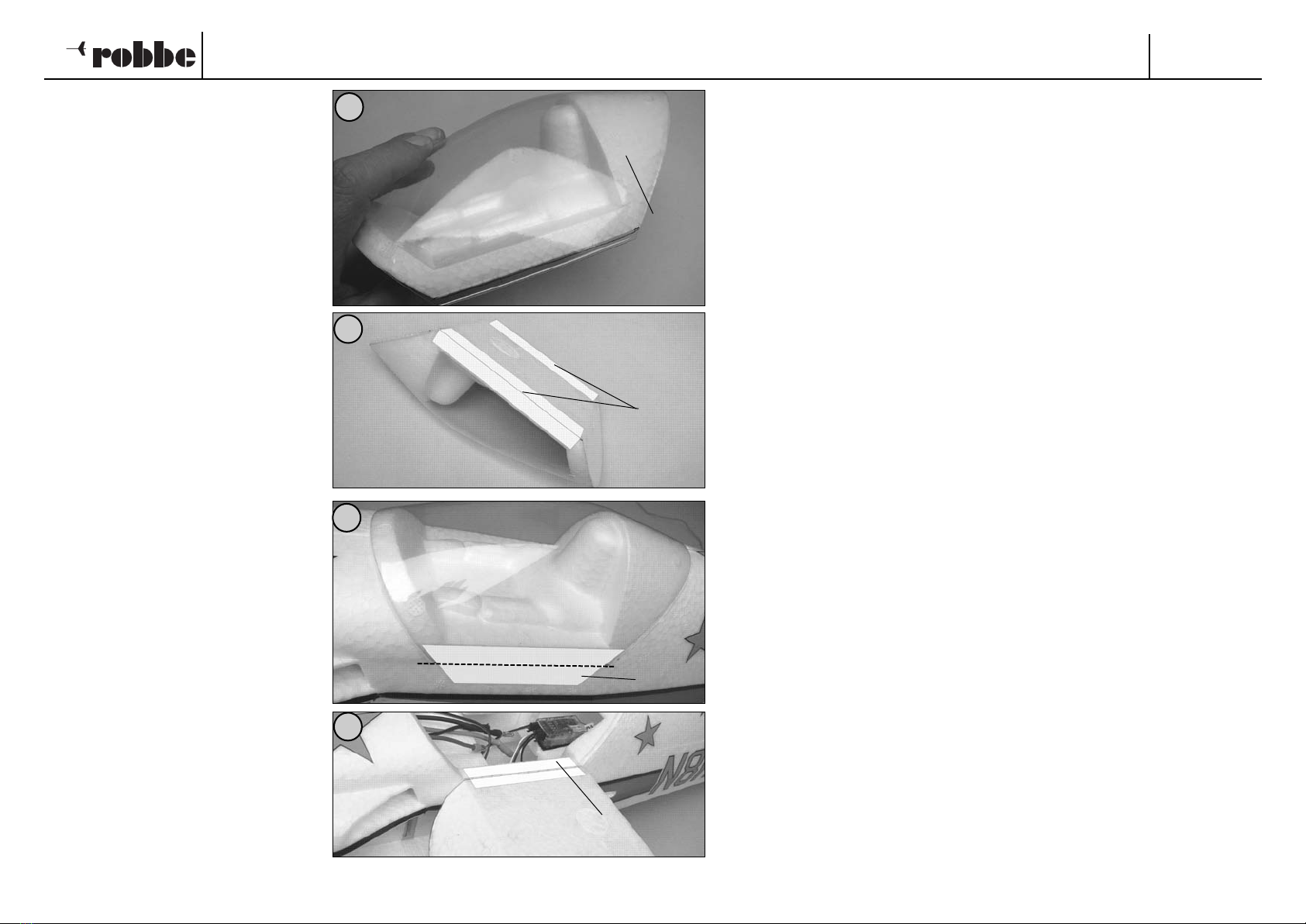
- Kabine 7.4 durch Beschneiden an das
Cockpit 7.5 anpassen.
- Kabine mit 2 Klebebandstreifen „K“
am Cockpit befestigen.
(Die Klebestreifen sind aus
Darstellungsgründen eingefärbt)
-Kabine aufsetzen und an der linken
Kante mit einem Klebebandstreifen
“K” am Rumpf befestigen.
- Kabine aufklappen und innen einen
Klebebandstreifen “K” über die ganze
Länge gegenkleben.
- Trim the edges of the canopy 7.4 to fit
neatly on the cockpit 7.5.
- Attach the canopy to the cockpit using
two strips of adhesive tape “K” (in the
picture the tape is shown coloured to
make it more easily visible).
- Fit the cabin assembly on the fuselage
and attach it using a further strip of
adhesive tape “K” as shown.
-Carefully raise the canopy using the
tape as a hinge, and apply a full-length
strip of tape “K” along the inside of the
hinge line.
- Ajuster la cabine 7.4 au cockpit 7.5 en
la découpant en conséquence.
- Fixer la cabine avec 2 morceaux de
ruban adhésif „K“ au cockpit.
(Pour des motifs de représentation et
de visibilité, les morceaux de ruban
adhésif sont teintés).
-Mettre la cabine en place et la fixer au
fuselage au niveau de l’arête gauche
avec un morceau de ruban adhésif
“K”.
-Rabattre la cabine et contre coller à
l’intérieur sur toute la longueur avec
un morceau de ruban adhésif “K”.
50
51
52
53
7.4, 7.5
“K”
“K”
“K”
Other ROBBE Aircraft manuals


