Robble Schluter Millennium 60 III PRO S 2875 User manual
No. S 2875
III PRO
3
DGB F
Inhaltsverzeichnis Contents Sommaire
Technische Daten:
Hauptrotordurchmesser:ca. 1500 mm
Heckrotordurchmesser: ca. 290 mm
Länge: ca. 1450 mm
Höhe: ca. 450 mm
Untersetzung: 7,5:1 / 8,57:1
Inhalt Seite
Warnhinweise 4
Vorwort 5/6
Hinweise 7-9
Stufe Inhalt Seite
1 Montage Basismechanik 10-17
2Montage Heckabtriebs-
gehäuse 18-19
3 Montage Getriebestufe 20-25
4 Montage Kufenlande-
gestell 25-29
5 Montage Rotorkopf 30-39
6 Montage
Heckrotorgetriebe 40-43
7 Montage Heckrohr und
Starrantrieb 44-47
8 Montage Motoreinheit 48-53
9 Montage RC-Anlage 54-65
10 Montage
Kabinenhaube 66-67
11 Hauptrotorblätter 68-70
12 Endkontrolle 70
13 Einstellen Blattspurlauf 70
14 Allgemeines zur
Programmierung der
Fernsteueranlage 71-74
Zeichnungen 75-85
Ersatzteilliste 86-91
Specification:
Rotor diameter: approx. 1500 mm
Tail rotor diameter: approx. 290 mm
Length: approx. 1450 mm
Height: approx. 450 mm
Gear ratio: 7,5:1 / 8,57:1
Contents Page
Warnings 4
Foreword 5/6
Notes 7-9
Stage Contents Page
1 Fitting the basicmechanic10-17
2 Fitting the tail rotor
drive housing 18-19
3 Fitting the gearbox stage 20-25
4 Fitting the skid
landing gear 25-29
5 Fitting the rotor head 30-39
6 Fitting the tail rotor
gearbox 40-43
7 Fitting the tail boom and
rigid drive 40-47
8 Fitting the engine train 48-53
9 Installing the receiving
system components 54-65
10 Fitting the canopy 66-67
11 main rotor blades 68-70
12 Final checks 70
13 Adjusting blade tracking 70
14 General information on
programming the radio
control system 71-74
Drawings 75-85
Parts list 86-91
Caractéristiques techniques:
Diamètre du rotor: approx. 1500 mm
Diamètre du rotor arrière:
approx. 290 mm
Longueur: approx. 1450 mm
Hauteur: approx. 450 mm
rapport de transmission: 7,5:1 / 8,57:1
Sommaire page
Avertissement: 4
Préface 5/6
Indications 7-9
Stade Sommaire Page
1 Montage du mécanisme
de base 10-17
2 Montage du carter de la
transmission arrière 18-19
3 Montage du mécanisme 20-25
4 Montage du train
d’atterissage 25-29
5 Montage de la tête de
rotor 30-39
6 Montage du mécanisme
du rotor arrière 40-43
7Montage du tube arrière
et d’entraînement rigide 44-47
8 Montage du bloc moteur 48-53
9 Mise en place de l’ensemble
de réception 54-65
10 Montage de la verrière de
cabine 66-67
11 Pales du rotor principal 68-70
12 Contrôle final 70
13 Réglage du tracking 70
14 Généralités concernant la
programmation de
l’ensemble de radio-
commande 71-74
Croquis 75-85
Liste des pièces 86-91

4
DGB F
Warnung: Warning: Avertissement:
Warnung:
Ein Modellhubschrauber ist kein
Spielzeug !
Der Betrieb durch Jugendliche sollte
immer unter Aufsicht eines
Erwachsenen erfolgen.
Ein Modellhubschrauber kann durch
unsachgemäßen Aufbau oder
fahrlässigen Betrieb zu schweren
Sach- und Personenschäden führen.
Die Antriebsenergie der Rotorblätter
zerstört alle Gegenstände, welche in
die Rotorebene gelangen.
Dies führt zwangsläufig zur
Unkontrollierbarkeit des Modells.
Störungen der Fernsteuerungsanlage
können jederzeit und ohne
Vorankündigung auftreten.
Ein Modellhubschrauber kann
jederzeit in jede beliebige Richtung
ausbrechen.
Deshalb immer ausreichend
Sicherheitsabstand halten.
Vor und nach jedem Flug ist der
komplette Modellhubschrauber auf
Schäden bzw. lose Teile zu
untersuchen.
Schon der Ausfall nur eines Teiles
führt möglicherweise zum Absturz.
Da Hersteller und Verkäufer keinen
Einfluß auf einen sachgerechten
Aufbau und ordnungsgemäßen
Betrieb des Modells haben, wird
ausdrücklich auf diese Gefahren
hingewiesen und jegliche Haftung
abgelehnt.
Das von Ihnen erworbene Modell
Millennium III PRO stammt aus der
Robbe-Schlüter Hubschrauber-
Produktfamilie.
Das Modell ist aufgrund seiner
Konstruktion als Trainer in wenigen
Stunden aufzubauen.
Das für den Aufbau und Betrieb
benötigte Werkzeug und Zubehör
entnehmen Sie bitte dem separaten
Zubehörblatt.
Warning:
Model helicopters are not playthings!
This model is not suitable for young
people under 16 years of age.
A model helicopter can cause serious
personal injury and damage to
property if built incorrectly or
operated incompetently.
The kinetic energy in the rotor blades
destroys any object which gets in
their way.
This inevitably results in a completely
uncontrollable model at the very least.
Interference may affect the radio
control system at any time and
without warning. If this should
happen, the helicopter could
immediately fly off in any direction.
To avoid these dangers please keep a
safe distance away from the model at
all times.
Check the whole of the helicopter for
damage and loose parts before and
after every flight.
If just a single part should fail, the
result could easily be a disastrous
crash.
Since we as manufacturer and your
model shop as supplier have no
control over the way you construct
and operate your model, and cannot
be sure of your competence and care,
we are unable to accept liability for
any damage caused. All we can do is
expressly to point out the hazards to
you.
The Millennium III PRO which you
have purchased is a member of the
renowned Robbe-Schlueter family of
helicopter products.
This model is of open trainer-type
construction and is therefore easy to
assemble and ready to fly in just a few
hours.
Please refer to the separate accessory
sheet for details of the tools and
accessories required to build and
operate the model.
Avertissement:
Un hélicoptère modèle réduit n’est
pas un jouet !
à ne pas confier à des jeunes de
moins de 16 ans.
Un modèle réduit construit sans soin
et mis en œuvre imprudemment est
susceptible de provoquer des dégâts
matériels et corporels considérables.
La force des pales en mouvement est
telle qu’elle est susceptible de
détruire les objets entrant dans leur
plan de rotation ce qui supprime tout
contrôle du modèle.
Des pannes de transmission de
l’ensemble de radiocommande
peuvent se produire à tout moment
sans avertissement préalable. Quelle
que soit son assiette de vol, un
hélicoptère est toujours susceptible
de décrocher.
C’est pourquoi il faut toujours
observer une certaine marge de
sécurité par rapport aux spectateur.
Après chaque vol il est recommandé
de vérifier l’intégrité de l’appareil et de
contrôler les éléments vissés.
Une seule pièce qui se désolidarise
est susceptible de provoquer la chute
de l’hélicoptère.
Étant donné que le constructeur et le
vendeur de l’appareil n’ont aucun
contrôle sur la qualité de la
construction et sur la conformité de la
mise en œuvre des modèles réduits,
ils en mentionnent les dangers en
dégageant leur responsabilité.
Le modèle Millennium III PRO que
vous venez d’acquérir est un membre
de la famille des hélicoptères robbe-
Schlüter.
Ses caractéristiques de construction
en font un modèle d’entraînement
monté en quelques heures.
L’outillage et les accessoires
nécessaires au montage et à la mise
en œuvre du modèle sont mentionnés
sur un feuillet autonome.

DGB F
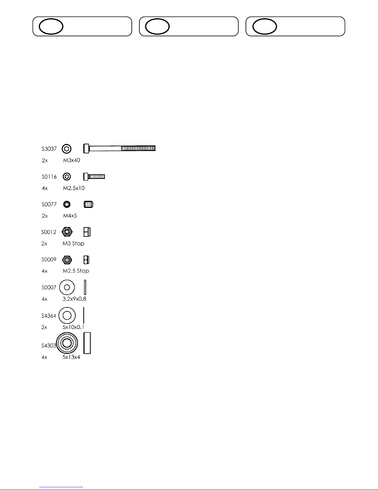
Notes on the radio control system:
All the pushrod lengths and servo
output arm lengths stated in the
building instructions assume the use
of Robbe/Futaba servos.
If you are using servos of different
make you may need to make minor
changes to these values.
The model is designed to take a
glowplug motor for helicopters.
The building instructions are divided
into sub-assemblies which are then
sub-divided into individual logical
steps. Each sub-assembly is
numbered, and is built using the parts
from the bag bearing the same
number.
An assembly drawing is provided to
accompany each stage of
construction, and you will find this a
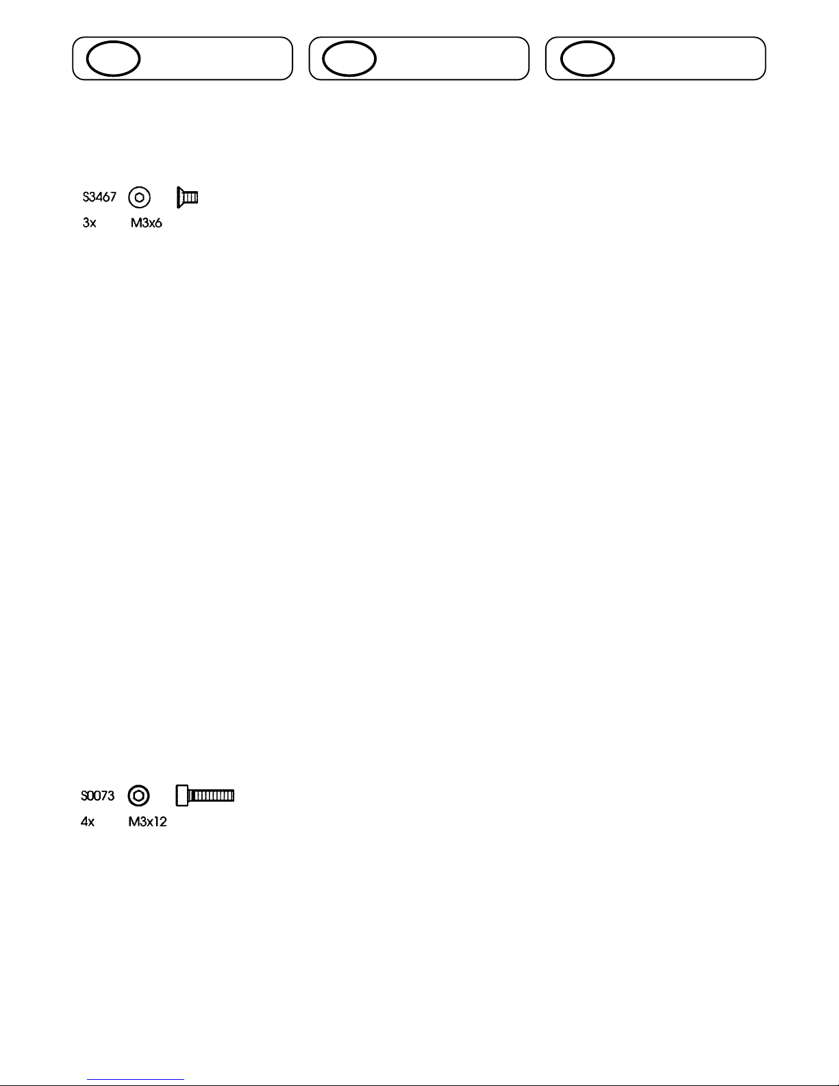
great help. Each drawing is supplied
with a full-size key to the screws,
washers and shim washers required,
so that you can be sure of using the
right parts.
The dimensions are stated in the
standard DIN format, e.g.:
Cheesehead screws:
M3 x 40 = diameter x length from
cheesehead to screw end
Countersunk screws:
3 x 20 = diameter x overall length
Grubscrews:
M3 x 3: diameter x overall length
Washers:
3.2 x 9 x 0.8 - internal diameter x
outside diameter x thickness
Nuts:
M3 self-locking nut - self-locking nut
with metric internal thread.
Each stage includes a number of hints
giving useful information relating to
the task in hand.
You will also find useful tips which are
of more general guidance, and will
help you later when operating the
model.
Recommandations concernant
l’ensemble de radiocommande:
toutes les longueurs de tringles et de
palonniers de servos fournies par la
notice de construction font référence
à des ensembles/servos robbe-
Futaba. La mise en place de servos
de fabrication étrangère vous engage
à rectifier de vous-même les cotes
mentionnées.
Pour la motorisation du modèle nous
recommandons un moteur spécial
hélicoptère.
La notice de construction est
structurée sur la base des modules
composant l’appareil et par étapes de
montage logiques. Chaque module
est numéroté et le sachet de pièces
correspondant porte le même numéro
dans la boîte de construction.
Pour chaque étape du montage est
présentée une illustration de la
construction. Pour identifier les vis,
les rondelles calibrées et les rondelles
vous trouverez dans la notice des
indications et une représentation á
l’échelle 1 des pièces.
Les cotes indiquées se réfèrent aux
cotes définies par les normes DIN; par
exemple:
vis à tête cylindrique:
M 3 x 40 = diamètre x longueur de la
vis cylindrique jusqu’à la fin du
filetage.
Vis à tête fraisée:
3 x 20 = diamètre x longueur totale
Vis sans tête:
M 3 x 3 = diamètre x longueur totale
rondelles:
3,2 x 9 x 8,0 = diamètre intérieur x
diamètre extérieur x épaisseur
écrous:
autoblocants M 3 = écrous
autobloquants avec diamètre
métrique intérieur.
Chaque étape de construction est
explicitée par des recommandations
dont il faut tenir compte pendant le
montage.
Par ailleurs nous vous donnons
quelques conseils susceptibles de
vous aider par la suite pour la mise en
œuvre du modèle.
Vorwort Foreword Préface
5
Hinweise zur verwendeten
Fernsteuerungsanlage:
Alle in der Bauanleitung angegebenen
Gestängelängen und
Servohebellängen
beziehen sich auf die Verwendung
von robbe/Futaba Servos.
Bei Einsatz von Servotypen anderen
Fabrikats können diese Maße leicht
abweichen.
Als Antrieb wird ein Motor in Heli-
Ausführung eingesetzt.
Die Bauanleitung ist nach
Baugruppen gegliedert und in
einzelne, logisch aufeinanderfolgende
Baustufen unterteilt. Jede Baugruppe
ist numeriert und entspricht jeweils
der Nummer aus dem Baukasten.
Zu jeder Baustufe erklärt eine
Montagezeichnung den
Zusammenbau. Zur Identifizierung der
Schrauben, Kugellager, Unterleg- und
Paßscheiben finden Sie bei jeder
Montagezeichnung eine Legende, in
der diese Teile im Maßstab 1:1
dargestellt sind.
Die Maßangaben beziehen sich auf
die nach DIN festgelegten Maße: z.B.
Zylinderkopfschrauben:
M3 x 40 = Durchmesser x Länge ohne
Zylinderkopf bis Schraubenende.
Senkschrauben:
M3 x 20 = Durchmesser x
Gesamtlänge einschließlich Kopf.
Stiftschrauben:
M3 x 3 = Durchmesser x
Gesamtlänge.
Unterlegscheiben:
3.2 x 9 x 0.8 = Innendurchmesser x
Außendurchmesser x Dicke.
Muttern:
M3 Stop = Stoppmutter mit
metrischem Innengewinde.
Bei den Baustufen finden Sie
ergänzende Hinweise, die bei der
Montage zu beachten sind.
Des weiteren finden Sie Tips, die
Ihnen auch bei dem späteren Betrieb
des Modells hilfreich sein werden.
6
DGB F
Vorwort: Foreword Préface
Parts whose numbers are printed in
the building instructions in square
brackets such as [S3268] are not
included in this kit.
Basic information on assembling
the model
You build the model in right-hand
rotation form. This term refer to the
direction of rotation of the main rotor
head as seen from above. Right-hand
rotation = clockwise (CW)
It is particularly important that you use
original replacement parts exclusively.
The number for each component is
printed next to the corresponding
part’s illustration in the replacement
parts drawing
Please keep these building
instructions in a safe place as you
may need them later when
dismantling, re-assembling and
repairing the helicopter. For the same
reason please keep the red check slip
and any supplementary sheets
supplied in the kit.
Always use the original Order No.
when ordering parts; this ensures that
you will receive your replacement
parts quickly and without fuss.
You will need to state the Check No.
and enclose your proof of purchase
(receipt) if you have a complaint or
wish to make a claim under
guarantee.
Les éléments accompagnés d’une
référence entre crochets par exemple
[S 3268] cités dans la notice se
rapportent à des composants qui ne
font pas partie de cette boîte de
construction.
Généralités concernant la
construction
Le modèle est à construire avec un
sens de rotation vers la droite.
Rotation vers la droite = dans le sens
des aiguilles d’une montre
Il est particulièrement important
d’utiliser des pièces détachées
originales. Les références des pièces
à indiquer à la commande figurent sur
les schèmas de cette notice.
Conservez cette notice et les
schémas joints car ils sont
indispensables pour toute réparation
ultérieure. Conserver également la
fiche de contrôle de qualité de
l’appareil de même que tous les
feuillets éventuellement joints.
Pour simplifier et accélérer toute
commande de pièce, mentionner
systématiquement la référence
originale.
Pour toute réclamation ou recours en
garantie, indiquer le numéro de
contrôle de qualité de la boîte de
construction et joindre le ticket de
caisse.
Teile, welche in eckigen Klammern
z.B. [S 3268] in der Bauanleitung
erwähnt werden, sind nicht
Bestandteil dieses Baukastens.
Grundsätzliches zum Aufbau
Dieses Modell wird rechtsdrehend
aufgebaut.
Unter rechtsdrehend versteht man die
Drehrichtung des Hauptrotors von
oben gesehen.
Rechtsdrehend = im Uhrzeigersinn
Es ist besonders wichtig, daß Sie nur
Originalersatzteile verwenden. Die
Artikelnummern stehen neben jedem
auf der Bauanleitung abgebildeten
Teil.
Bitte bewahren Sie diese
Bauanleitung für spätere Montage-
oder Reparaturarbeiten unbedingt auf.
Ebenso sollten Sie den roten
Kontrollschein sowie alle eventuell
beiliegenden Zusatzblätter gut
aufbewahren.
Um eine zügige und unkomplizierte
Ersatzteilversorgung zu
gewährleisten, sollten Sie bei einer
Bestellung immer die Original
Bestellnummer verwenden.
Sollte ein dringend benötigtes
Ersatzteil einmal nicht bei Ihrem
Händler vorrätig sein, so haben Sie
die Möglichkeit, alle Ersatzteile schnell
und unkompliziert direkt bei robbe zu
beziehen. Hinweise hierzu entnehmen
Sie bitte der aktuellen Preisliste.
Die Adresse lautet:
robbe Modellsport GmbH & Co. KG
Ersatzteil-Schnell-Dienst (ESD)
Postfach 1108
D-36352 Grebenhain
Telefon: 06644/87-222
Telefax: 06644/ 87333
Für eventuelle Reklamationen bzw.
Gewährleistungsfälle ist die Angabe
der Kontrollnummer sowie Beilage
des Kaufbelegs zwingend notwendig.
7
DGB F
Hinweise Notes Á noter
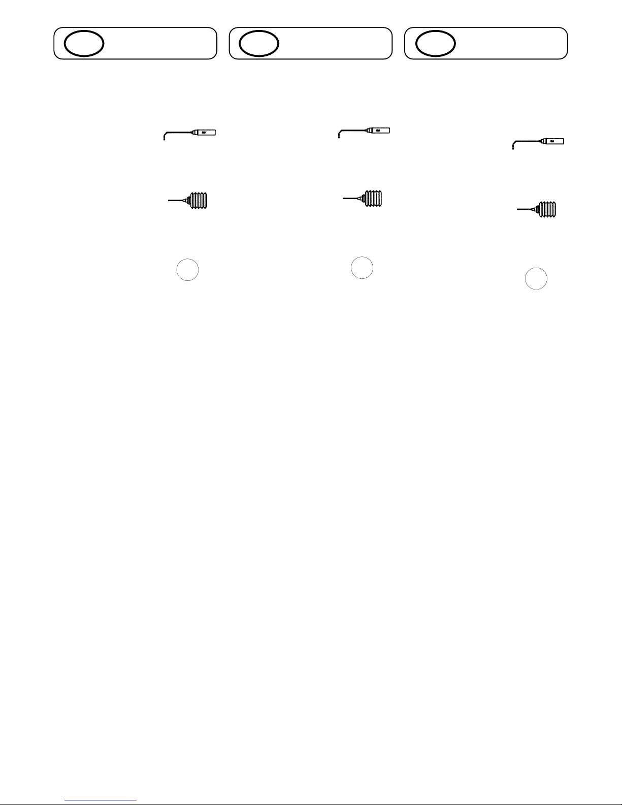
Notes on construction:
You will see three different symbols
used in these instructions:
1.Oil can
- Use synthetic oil
[robbe No. 5530] at this point in
assembly.
2:Grease tube
- Use grease (robbe No.
S1315] at this point in
assembly.
3:Loctite
- Use Loctite medium-
strength thread-lock
fluid, (robbe No. 5074)
on this screwed joint.
All threaded parts and screws must
be de-greased before applying
thread-lock fluid.
Unless stated otherwise use Loctite
on all metal-to-metal screwed jounts.
Tip:
Wherever possible apply Loctite on a
fine-tipped tool (needle), and apply
the fluid to the internal threaded hole.
If you apply Loctite on the external
threaded part excess fluid may be
pushed out into adjacent ballraces or
plain bearings, and the bearing may
then seize.
How a model helicopter works:
A powered aircraft with fixed wing
and tail requires the forward thrust of
the propeller to take off and fly. The
forward motion through the air causes
the wing to produce lift; the model lifts
off and flies. In contrast helicopters
require no forward movement. The
wing takes the form of a huge rotating
propeller, or airscrew, mounted above
the fuselage. That is why helicopters
are also termed rotary-wing aircraft.
Remarques concernant la
construction:
dans la notice vous trouverez
différents symboles:
1 la burette d’huile
- à cet endroit il faut,
au montage, utiliser de l’huile
synthétique robbe [réf. robbe 5530].
2 le tube de graisse
- à cet endroit il faut, au
cours du montage,
appliquer de la graisse robbe (réf.
robbe S1315).
3 Loctite
- à cet endroit il faut, au
cours du montage,
appliquer du frein de filets (Loctite
réf. robbe 5074).
Avant d’appliquer le produit,
dégraisser le filetage et les vis.
Sauf indication contraire, la colle
Loctite doit être utilisée pour chaque
couple vis / filetage de métal.
Un conseil:
lorsque vous appliquez du Loctite, il
faut, autant que possible, déposer le
produit avec une épingle sur le
filetage de taraudages intérieurs. Si
vous appliquez le Loctite directement
sur le filet des vis, vous risquez d’en
introduire dans les roulements à billes
ou les paliers lisses ce qui risque de
les gripper.
Mode de fonctionnement d’un
hélicoptère
Un appareil volant à moteur a besoin
d’une aile et d’empennages et de la
traction d’une hélice. Son
déplacement vers l’avant produit une
portance au niveau des plans fixes qui
assure sa sustentation et son vol.
L’hélicoptère, par contre, n’a pas
besoin de se déplacer vers l’avant,
son aile est une hélice rotative
surdimensionnée disposer au-dessus
du fuselage. L’hélicoptère fait partie
ainsi de la catégorie des giravions.
Hinweise zum Bau:
Sie finden in der Anleitung drei
verschiedene Symbole:
1:Ölkanne
- hier muß bei der
Montage Synthetiköl
[robbe Nr. 5530] verwendet werden.
2:Fett
- hier muß bei der
Montage Fett (robbe
Nr. S1315) verwendet werden.
3:Loctite
- hier muß bei der
Montage
Schraubensicherung
mittelfest (robbe Nr. 5074)
verwendet werden.
Vor dem Aufbringen der
Schraubensicherung müssen alle
Gewinde und Schrauben entfettet
werden.
Wenn nicht anders beschrieben ist
Loctite immer dort zu verwenden, wo
die Paarung Metallschraube/ Gewinde
auftritt!
Tip:
Bei Verwendung von Loctite sollte die
Flüssigkeit nach Möglichkeit mit einer
feinen Spitze (Nadel) in die
Innenbohrung des Gewindes gebracht
werden. Durch Aufstreichen auf das
Schraubengewinde kann
überschüssiges Loctite in Kugel- oder
Gleitlager dringen und so zum
Verkleben der Lager führen.
Die Funktionsweise eines
Modellhubschraubers:
Ein Motorflugzeug mit Tragflächen
und Leitwerk benötigt den Vortrieb
der Luftschraube. Durch die
Vorwärtsbewegung wird an der
Tragfläche Auftrieb erzeugt; das
Modell hebt ab und fliegt.
Der Hubschrauber benötigt im
Gegensatz dazu keine
Vorwärtsbewegung. Die Tragfläche ist
wie eine überdimensionale
Luftschraube drehbar über dem
Rumpf gelagert. Daher wird ein
Hubschrauber auch als Drehflügler
bezeichnet.
L
L
L

8
DGB F
Hinweise Notes Á noter
Die Entstehung des Auftriebs am
Hauptrotor:
Wie bei einem Tragflügel sind die
Rotorblätter profiliert und unter einem
bestimmten Winkel gegen die
Luftströmung angestellt. Der von der
Luft umströmte Rotor liefert, wenn er
in Drehung versetzt wird, Auftrieb. Ab
einer bestimmten Drehzahl und
Anstellwinkel der Rotorblätter wird die
nach oben gerichtete Auftriebskraft
größer als die Gewichtskraft. Der
Hubschrauber hebt vom Boden ab
und steigt nach oben.
Entsprechen sich Auftrieb und
Gewicht, so verharrt der
Hubschrauber im Schwebeflug, wird
der Auftrieb kleiner, geht er in den
Sinkflug über.
Der Drehmomentausgleich:
Die vom Motor auf den Rotorkopf
übertragene Antriebsleistung erzeugt
ein Drehmoment. Dies hat zur Folge,
daß sich der Rumpf entgegen der
Rotordrehrichtung dreht.
Diese Rumpfdrehung ist nicht
erwünscht und muß ausgeglichen
werden. Dazu ist am Rumpfende ein
Heckrotor montiert. Die ebenfalls
profilierten und angestellten Blätter
des Heckrotors erzeugen eine seitlich
angreifende Kraft. Dadurch wird der
Rumpf an der Drehung gehindert; das
Drehmoment wird aufgehoben.
Die Steuerung eines
Modellhubschraubers
Das wichtigste
Unterscheidungsmerkmal zum
Flächenflugzeug ist, daß das
Antriebselement, der Hauptrotor,
gleichzeitig wichtigstes Steuerelement
ist.
Zur Steuerung des Hubschraubers
dienen sowohl der Haupt- als auch
der Heckrotor. Am Hauptrotorkopf
befindet sich ein sogenannter
Hilfsrotor, der die Steuerbewegungen
auf den Hauptrotor überträgt.
How the main rotor produces
upthrust (lift):
The rotor blades have a distinctive
profile, or airfoil section, just like a
normal wing, and are set at a
particular angle relative to the airflow.
When the rotor is made to spin, it
produces lift, or upthrust, as it moves
through the air. At a particular
rotational speed and angle (pitch) of
the rotor blades, the upthrust rises to
a point where it is greater than the
force of gravity. The machine then lifts
off the ground and climbs.
If rotor upthrust is equal to the
model’s weight, the helicopter
remains stationary in the air, or
hovers. If rotor upthrust is reduced,
the helicopter descends.
Torque compensation:
It is the power of the motor which
causes the rotor head to rotate, and
the term for this rotational power is
torque. The effect, or reaction of the
torque is to turn, or yaw, the fuselage
in the opposite direction to the rotor.
This rotation of the fuselage is not
desirable, and must be countered.
Torque compensation is the task of
the tail rotor, mounted at the tail end
of the fuselage. The tail rotor blades
also feature an airfoil section and
variable pitch, and the thrust they
produce is directed sideways, in the
opposite direction to main rotor
torque. When tail rotor thrust equals
main rotor torque, the fuselage stops
rotating about the vertical axis.
Controlling a model helicopter
The crucial difference between a
fixed-wing aircraft and a helicopter is
that the latter’s power element - the
main rotor - is also its primary control
element.
The helicopter is controlled by means
of the main rotor and the tail rotor.
The main rotor head is „helped“ by an
auxiliary rotor which transmits the
servos’ control movements to the
main rotor.
Génération de la portance au
niveau du rotor principal:
Comme l’aile d’un avion à plans fixes,
les pales de l’hélicoptère sont
profilées et présentent un certain
angle d’attaque contre les
déplacements d’air. Le rotor
enveloppé d’air délivre, lorsqu’il est
mis en mouvement, une certain
portance. à partir d’un régime
déterminé et avec un certain angle
d’incidence des pales, la poussée
vers le haut dépasse l’inertie du poids
propre du modèle qui quitte alors le
sol et entreprend son ascension.
Lorsque le poids et la portance sont
égaux, l’hélicoptère reste en
sustentation et il descend lorsque la
portance diminue encore.
Compensation du moment de
rotation
La puissance transmise du moteur au
rotor principal produit un couple de
rotation qui entraîne le fuselage dans
un mouvement de rotation opposé au
sens de rotation des pales. Cet effet
n’est pas souhaité et doit être contré.
Pour ce faire, est installé le rotor
arrière à l’extrémité du fuselage. Les
pales du rotor arrière également
profilées et pourvues d’un angle
d’attaque génèrent un couple
transversal antagoniste. On empêche
ainsi le fuselage de tourner sur lui-
même en produisant un anticouple.
Commande d’un hélicoptère
modèle réduit
La distinction la plus sensible entre un
avion à aile et un hélicoptère est que
l’élément assurant la portance
constitue également l’élément
essentiel de pilotage.
Pour piloter un hélicoptère on exploite
aussi bien le rotor principal que le
rotor arrière. Au-dessus du rotor
principal et solidaire du rotor principal
se trouve un „rotor auxiliaire“ qui
transmet les mouvements au rotor
principal.

9
DGB F
Hinweise Notes Á noter
Die auf der Hauptrotorwelle
angebrachte Taumelscheibe, welche
in allen Richtungen verstellbar ist,
dient dabei als mechanisches
Übertragungsglied für die
Steuerbefehle. Zur Ansteuerung der
Taumelscheibe dienen das Pitch, Roll-
und Nickservo.
Die Funktion der Taumelscheibe:
Um vorwärts, rückwärts bzw. seitlich
fliegen zu können, muß die
Rotorkreisebene des Hauptrotors in
die gewünschte Flugrichtung geneigt
werden. Dazu werden die
Anstellwinkel der Rotorblätter pro
Umlauf verändert.
= zyklische Blattverstellung.
Um steigen und sinken zu können
werden die Rotorblätter gleichsinnig
angesteuert.
= kollektive Blattverstellung
Gesteuert werden 4
Hauptfunktionen:
- Steigen und Sinken: “Pitch, Gas“
Über gleichsinnige Veränderung des
Anstellwinkels der Hauptrotorblätter
bei gleichzeitiger Gasänderung.
- Rollen: “Roll“
(Bewegung um die Längsachse)
Über seitliches Neigen der
Hauptrotorebene.
- Nicken: “Nick“
(Bewegung um die Querachse):
Über Neigen der Hauptrotorebene
nach vorn und hinten.
- Gieren: “Heck“
(Bewegung um die Hochachse):
Über Anstellwinkelveränderung der
Heckrotorblätter.
The swashplate serves as the
mechanical means of transmitting the
control commands from the servos to
the rotor. It is capable of movement in
all directions, and is mounted on the
main rotor shaft, or mast. The
swashplate is controlled by the
collective pitch servo, the roll servo
and the pitch-axis (forward/back)
servo.
How the swashplate works:
In order to fly forward, back and to
either side, the helicopter’s main rotor
disc has to be inclined in the
corresponding direction. In fact, the
whole rotor disc does not tilt; the
same effect is achieved by altering the
pitch angle of the rotor blades
according to their position on the
disc. This is called cyclic pitch
variation.
To control the machine’s rate of climb
and descent the pitch of the rotor
blades is varied by equal amounts;
this is termed collective pitch
variation.
The pilot controls four primary
functions:
- Climb and descent: „collective
pitch / throttle“
This function varies the pitch of both
main rotor blades, and is coupled to
the throttle to compensate for the
varying power absorption of the rotor.
- Roll: „roll-axis“
(movement around the longitudinal
axis)
Controlled by tilting the main rotor
plane to one side or the other.
- Pitch: „forward/back cyclic“
(movement around the pitch axis)
Controlled by tilting the main rotor
plane forward or back.
- Yaw: „tail rotor“
(movement around the vertical axis)
Controlled by varying the pitch angle
of the tail rotor blades.
Le plateau cyclique, susceptible de se
déplacer dans tous les sens, installé
sur le rotor principal constitue le
module mécanique de transfert des
instructions de pilotage.
L’asservissement du plateau cyclique
est assuré par les servos de pas, de
roulis et de tangage.
Le fonctionnement du plateau
cyclique:
Pour pouvoir voler en translation
horizontale en avant, en arrière et sur
les côtés, il faut incliner le plan de
rotation du rotor dans la direction
souhaitée. Pour ce faire, l’angle
d’incidence des pales est modifié sur
une révolution. Il s’agit du pas
cyclique. Pour monter ou descendre,
il faut modifier simultanément la
position des pales dans le même
sens. Il s’agit du pas collectif.
Quatre fonctions principales sont
asservies:
- montée et descente: „pas, gaz“
Par une modification dans le même
sens de l’angle d’incidence des pales
du rotor principal avec un
changement simultané des gaz;
- roulis: „roulis“
(mouvement sur l’axe longitudinal)
par une inclinaison latérale du plan de
rotation du rotor;
- tangage: „tangage“
(mouvement sur l’axe transversal):
par une inclinaison du plan de rotation
du rotor vers l’avant ou vers l’arrière;
- direction: „lacet“
(mouvement sur l’axe de lacet“
Par changement de l’angle d’attaque
des pales du rotor arrière.
10
Baustufe / Stage / Stade: 1
III PRO

DGB F
1.0 Montage basic mechanic
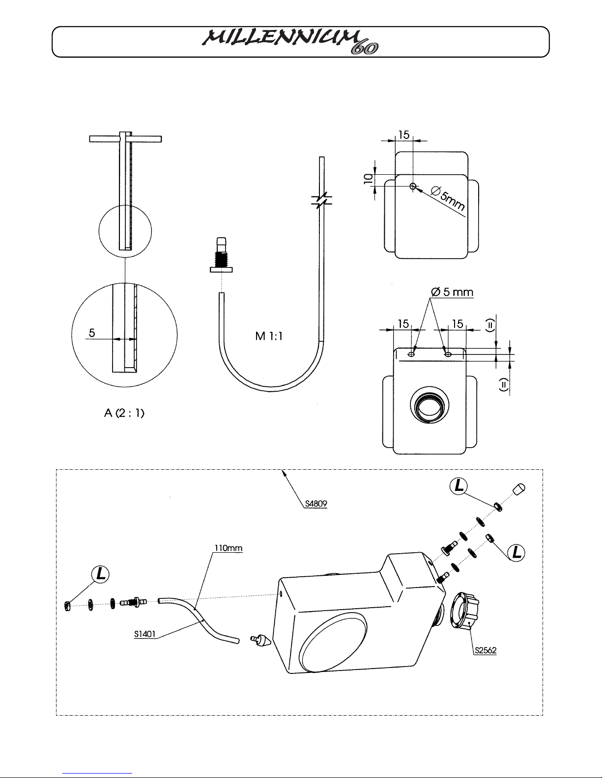
1.1 Fitting the fueltank:
Tip:
We recommend that you cut the holes
in the fueltank using a length of 5 mm
Ø brass tubing, countersunk to a
sharp edge at one end (see sketch
2:1), (not included).
This cuts a clean hole and produces
no swarf to contaminate the tank.
Note:
A piece of wire is a useful tool for
fitting the fueltank nipples. Bend it
according to the sketch 1:1.
Caution:
The clunk weight must be free to
move inside the tank, and must not
foul the rear face of the fueltank.
1.0 Montage du mécanisme de
base
1.1 Montage du réservoir
Un conseil:
Pour réaliser les orifices du réservoir,
il est possible d’utiliser un tube de
laiton de Ø 5 mm fraisé à l’intérieur.
(schéma 2e), (ne pas contenu dans la
boîte de construction).
On évite ainsi de constituer des
copeaux qui risquent de tomber dans
le réservoir.
À noter:
Pour le montage des raccords du
réservoir, il est possible d’utiliser un
morceau de fil de fer. Le plier selon le
croquis 1e.
Attention:
Le plongeur installé dans le réservoir
doit être dégagé et ne pas venir
s’appuyer sur la paroi arrière du
réservoir.
Baustufe: 1 Stage: 1 Stade: 1
11
1.0 Montage Basismechanik
1.1 Montage Tank:
Tip:
Zur Herstellung der Tankbohrungen
kann ein innen angesenktes
Messingrohr mit Ø 5 mm benutzt
werden (Skizze 2:1), (nicht im
Lieferumfang).
Dadurch entsteht kein Grat und es
fallen keine Späne in den Tank.
Hinweis:
Zur Montage der Tankanschlüsse
kann ein gebogener Stahldraht
benutzt werden - siehe Skizze 1:1.
Achtung:
Tankpendel muß im Tank frei pendeln
können und darf nicht an der hinteren
Tankwand anliegen.
12
Baustufe / Stage / Stade: 1
III PRO

13
DGB F
Baustufe: 1 Stage: 1 Stade: 1
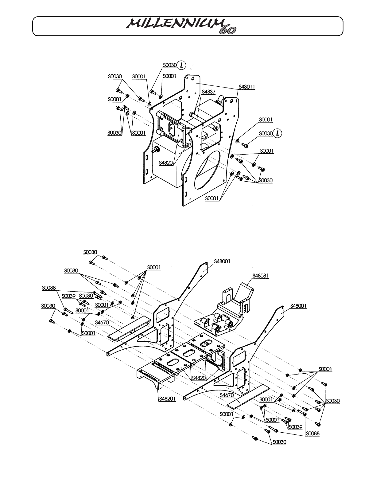
1.2 Fitting the back side-frames
1.3 Fitting the front side-frames
Note: if the throttle servo is already
available, it should be installed in the
left-hand side frame before you fit the
front side frames, as described in
Stage 9.5. This makes it easier to
install the servo.
1.2 Montage des plaques latérales
arrière
1.3 Montage des plaques latérales
avant
À noter : lorsque le servo des gaz est
déjà présent, il faut, avant d'installer le
montant latéral avant, selon le stade
de montage 9.5, l'implanter dans le
montant gauche. Cette procédure
facilite la mise en place du servo.
1.2 Montage Seitenplatten hinten
1.3 Montage Seitenplatten vorne
Hinweis: Sofern das Gasservo schon
vorhanden ist, sollte es vor der
Montage der vorderen Seitenplatten
gemäß Baustufe 9.5 in die linke
Seitenplatte eingesetzt werden. Dies
erleichtert den Einbau des Servos.

14
Baustufe / Stage / Stade: 1
III PRO
S3522

15
DGB F
Baustufe: 1 Stage: 1 Stade: 1
1.4 Montage Winkelhebel und
Seitenplatten oben
1.4.1 Montage Winkelhebel
1.4.2 Montage Seitenplatten oben
1.4 Fitting the bellcranks and top
side-frames
1.4.1 Fitting the bellcranks
1.4.2 Fitting the top side-frames
1.4 Montage du levier coudé et des
plaques latérales haut
1.4.1 Montage du levier coudé
1.4.2 Montage des plaques
larérales haut
S3522
16
Baustufe / Stage / Stade: 1
III PRO
17
DGB F
Baustufe: 1 Stage: 1 Stade: 1
1.5 Zusammenbau Seitenplatten 1.5 Fitting side-frames 1.5 Installation des plaques
latérales
Baustufe / Stage / Stade: 2
18
III PRO
Baustufe: 2 Stage: 2 Stade: 2
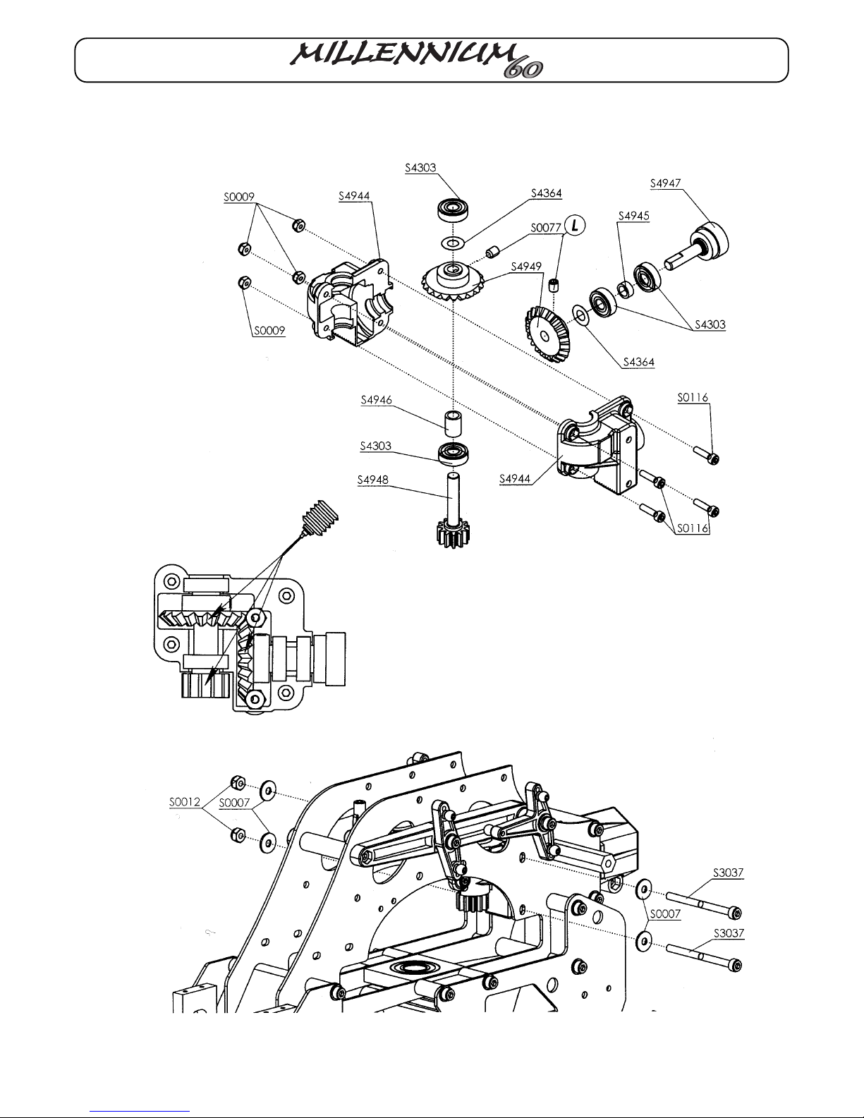
2.0 Heckabtriebsgehäuse
Heckgetriebe nach Skizze montieren.
Nach Einbau zwischen die
Seitenplatten und Festziehen der
Schrauben (S3037) stellt sich das
korrekte Getriebespiel ein.
2.0 Tail rotor drive housing
Assemble the tail rotor gearbox as
shown in the sketch. The correct
gearbox meshing clearance is set
automatically when the gearbox is
installed between the side frames and
the screws (S3037) are tightened.
2.0 Carter de la transmission arrière
Monter le mécanisme du rotor arrière
selon les indications du schéma.
Après mise en place entre les
montants latéraux et serrage des vis
(S3037) le jeu à l'engrenage correct
s'établit de lui-même.
19
DGB F

III PRO
20
Baustufe / Stage / Stade: 3
21
DGB F
Baustufe: 3 Stage: 3 Stade: 3
3.0 Montage Getriebestufe
3.1 Montage Stirnrad Z 60:
3.2 Montage Freilauf
Tip:
Schrauben (S0073) gleichmäßig über
Kreuz anziehen, so daß die Zahnräder
satt am Freilaufgehäuse (S4607)
anliegen.
Die Freilaufhülse (S4610) muß sich in
die gezeigte Richtung frei drehen
lassen (Pfeil).
3.0 Fitting the gearbox stage
3.1 Fitting the gear 60 T:
3.2 Fitting the freewheel
Tip:
Tighten the screws (S0073) evenly,
working alternately from side to side,
so that the gears rest evenly on the
freewheel (S4607).
You must be able to turn the sleeve
(S4610) of the freewheel according to
the drawing (arrow).
3.0 Montage du 1er niveau du
mécanisme
3.1 Montage de la couronne 60 D
3.2 Montage de la roue libre
Un conseil:
Serrer les vis (S0073) de manière
homogène en croisant de sorte que
les pignons s’appuient parfaitement
sur la roue libre (S4607)
Contrôlez s’il est possible de tourner
le manchon (S4610) de la roue, libre
selon le croquis (flèche).
Table of contents
Popular Toy manuals by other brands

FUTABA
FUTABA GY470 instruction manual

LEGO
LEGO 41116 manual

Fisher-Price
Fisher-Price ColorMe Flowerz Bouquet Maker P9692 instruction sheet

Little Tikes
Little Tikes LITTLE HANDIWORKER 0920 Assembly instructions

Eduard
Eduard EF-2000 Two-seater exterior Assembly instructions

USA Trains
USA Trains EXTENDED VISION CABOOSE instructions


