manuals.online logo
Brands
  1. Home
  2. •
  3. Brands
  4. •
  5. Robertshaw
  6. •
  7. Accessories
  8. •
  9. Robertshaw 570B Series User manual

Robertshaw 570B Series User manual

Model 570B Series
Two-wire Vibration Sensor
98549 Rev.G.1 1/04
FEATURES:
• Corrosion resistant
• ESD protection
• Reverse wiring protection
• Overload protection
• Hermetic
• No trim pots
SPECIFICATIONS
DYNAMIC
Output (±5% of Full Scale)............................................. 4-20 mA DC
Vibration Range ............................................................. see table below
Frequency Response:
–3 dB ..................................................................... see table below
Repeatability .................................................................. ±2%
Resonant Frequency, mounted, nominal ....................... see table below
Transverse Sensitivity, max. .......................................... 5%
ELECTRICAL
Power Requirements (Two wire loop power):
voltage source........................................................ 10 VDC - 30 VDC
Loop Resistance1at 24 VDC, maximum........................ 700Ω
Turn on Time.................................................................. <30 seconds
Grounding ...................................................................... Case isolated, internally
shielded
ENVIRONMENTAL
Temperature Range....................................................... –40 to 85°C
Vibration Limit ................................................................ 250 g peak
Shock Limit .................................................................... 2,500 g peak
Electromagnetic Sensitivity, equiv. g ............................. 10 µg/gauss
Sealing ........................................................................... hermetic, NEMA 4X, IP68
PHYSICAL
Weight............................................................................ 162 grams
Sensing Element Design................................................ PZT ceramic / shear
Case Material................................................................. 316L stainless steel
Mounting ........................................................................ 1/4 - 28 tapped hole
Output Connector........................................................... 2-pin, MIL-C-5015 style
Pin A ............................................... plus (+) White
Pin B ............................................. minus (–) Black
Cabling2......................................................................... Two conductor shielded
(See Table 1 on back)
Torque Limit................................................................... 30 in lbs. max
Warranty ........................................................................ 1 year
NOTES: 1Maximum loop resistance can be calculated by:
Vpower – 10 V
RL(max) = -------------------------
20 mA
Loop resistance is the sum of wiring
resistance and the load resistor.
2 Cable resistance equals 40 ohms, total per 1000 ft.
ACCESSORIESSUPPLIED: 1/4-28mountingstud.
Due to continued research and development, the Manufacturer reserves the right to amend these specifications without notice.
Robertshaw Industrial Products Division
1602 Mustang Drive
Maryville, Tennessee 37801 Telephone:
(865) 981-3100
Fax: (865) 981-3168
Model Mode Range Frequency Resonant
Response Frequency
570B-A acceleration 0 - 5 g peak 2 Hz - 2 kHz 28 kHz
570B-B acceleration 0 - 10 g peak 2 Hz - 2 kHz 28 kHz
570B-C acceleration 0 - 20 g peak 2 Hz - 2 kHz 28 kHz
570B-D velocity 0 - 0.5 IP peak 2 Hz - 2 kHz 28 kHz
570B-E velocity 0 - 1 IP peak 2 Hz - 2 kHz 28 kHz
570B-F velocity 0 - 2 IP peak 2 Hz - 2 kHz 28 kHz
TABLE
Industrial Products Division
2 pin
connector
1 1/16" hex
1/4-28
mounting hole
1.12"
2.12"
2.80"
Typical
Power Source RLmax
Voltage
20 500
24 700
26 800
Typical Circuit
Model 570
+
–
DC Power
Supply
RLOAD
Signal Measuring Circuit
Pin A
Pin B
+
–
Mounting Instructions
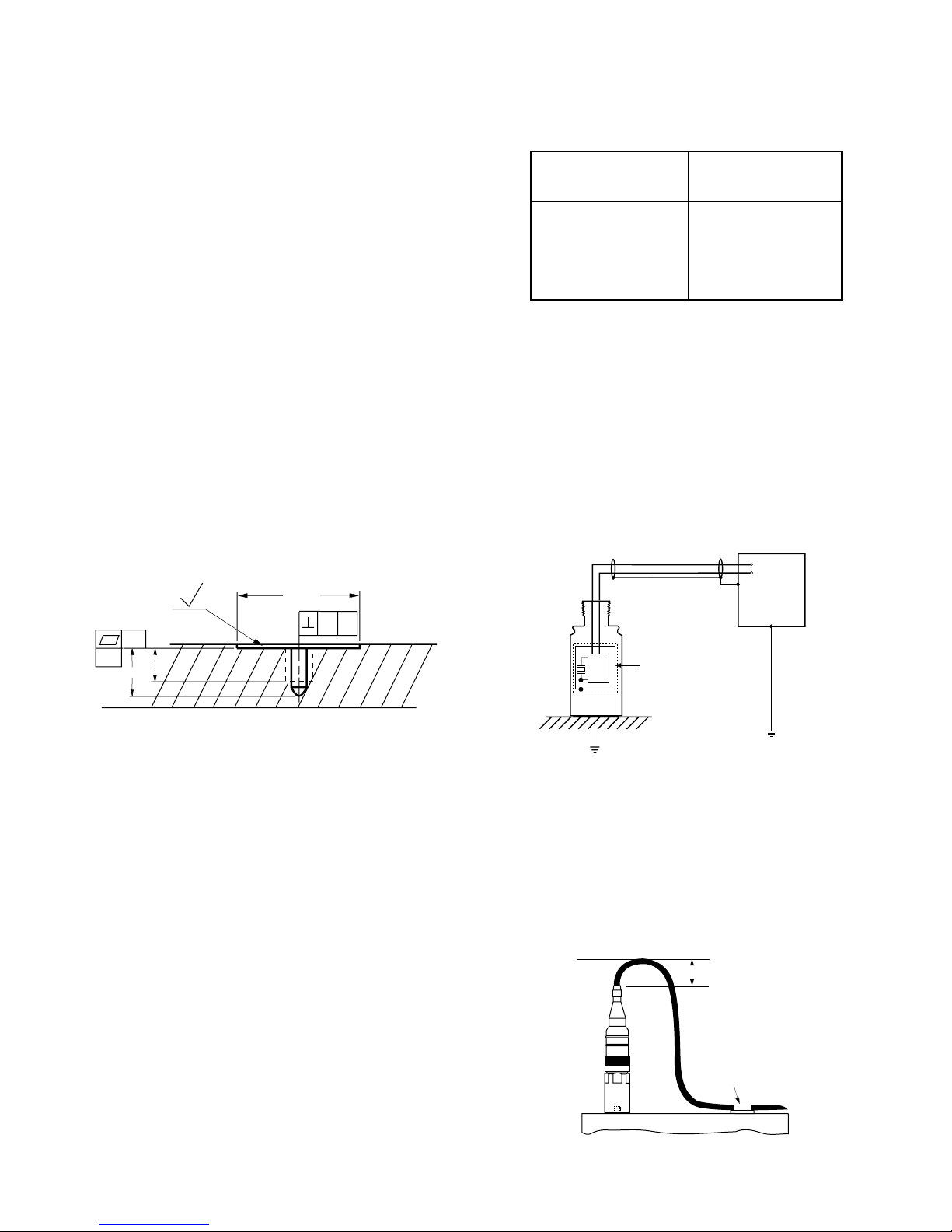
The mounting point on the structure should be faced to a
diameter of 1.25 inches. For measurements involving
frequencies above 1 kHz, the surface should be flat within 1
mil and have surface texture no greater than 32 microinches.
The tapped hole must be perpendicular to the mounting
surface and at least two threads deeper than the stud. This will
prevent a gap between the sensor and the mounting surface–
producing optimum frequency response. (see Figure 1).
Proper screw torque on the mounting stud is also required.
Under-torquing the sensor reduces the stiffness of the
coupling. Over-torquing can cause permanent damage to the
sensor. It is recommended that 1/4-28 stud be torqued to a
maximum value of 30 inch-pounds.
Before stud mounting the sensor, a coupling fluid should be
applied to the mating surfaces. The coupling fluid protects the
mounting surface and optimizes the frequency response by
increasing the coupling stiffness. Suggested coupling fluids
are machine oil or vacuum grease. It is recommended that a
thread adhesive such as Loctite 222 be used.
Cable Routing and Electromagnetic Interference
Walkie-talkies, power lines, or even electrical sparks may
cause signal interference. The following guidelines will
eliminate many measurement errors due to electromagnetic
radiation and electrostatic discharge (ESD).
Assure that high quality, well shielded cables are used. If
cable splices are made, complete shielding must be
maintained.
Proper cable routing is imperative. Never run sensor cable
alongside AC power lines; cables must cross AC power lines
at right angles. Where possible, provide a separate grounded
conduit to enclose the sensor cable. In addition, route the
cable away from radio transmission equipment, motors/
generators, and transformers. Finally, avoid routing the cable
through areas prone to ESD. Even though Robertshaw
sensors are protected against ESD failure, temporary
distortion signals may appear at the output.
Cable Grounding and Ground Loops
In order to provide proper shielding and prevent ground
loops, cable grounding should be carefully considered.
For sensors using two conductor/shielded cable, the power is
carried on one lead and the return on the other. The cable
shield serves to protect the signal from ESD and
electromagnetic interference (EMI). The shield should be
grounded at only one point. Figure 2 shows a typical cable
connection scheme.
Cable Anchoring
After mounting the sensor, the cable should be anchored to
reduce stress at the cable terminations. When securing the
cable, leave enough slack to allow free movement of the
sensor. Figure 3 shows a recommended cable anchoring
technique.
Cable
Clamp
Machine Surface
Figure 3: Cable Anchoring
Allow 2 inches
minimum bend
radius
Table 1: Cable versus Cable Length
Figure 2: Multiconductor/Shield Configuration
Internal Shield
Isolated from Housing
Readout
Equipment
+
–
Electronics
Part Number NEMA 4X
Cable Length
086568A0016 16 Ft.
086568A0032 32 Ft.
086568A0064 64 Ft.
086568A0112 112 Ft.
Note: IP68 cable available by special order.
.004 A
.001
—A—
1.25" min.
.25
.35
32
Figure 1: Stud Mounting: Surface Preparation
Surface
Facing

This manual suits for next models

6

Other Robertshaw Accessories manuals

Robertshaw 84370 Series User manual

Robertshaw

Robertshaw 84370 Series User manual

Robertshaw 84374 Series User manual

Robertshaw

Robertshaw 84374 Series User manual

Robertshaw 9020i User manual

Robertshaw

Robertshaw 9020i User manual

Popular Accessories manuals by other brands

Vixen GP2 Mounting guide

Vixen

Vixen GP2 Mounting guide

iHome iSB01 quick start guide

iHome

iHome iSB01 quick start guide

AeroDesignWorks HORNET-III manual

AeroDesignWorks

AeroDesignWorks HORNET-III manual

KMC Controls SSS-1000 Series installation guide

KMC Controls

KMC Controls SSS-1000 Series installation guide

Aurora AU-A1ZBDSS quick guide

Aurora

Aurora AU-A1ZBDSS quick guide

M-S Cash Drawer EP-125KPC supplementary guide

M-S Cash Drawer

M-S Cash Drawer EP-125KPC supplementary guide

Quincy lab 140 Series operating manual

Quincy lab

Quincy lab 140 Series operating manual

Takex PXB-50F instruction manual

Takex

Takex PXB-50F instruction manual

VERTBAUDET 70303-0084 instruction manual

VERTBAUDET

VERTBAUDET 70303-0084 instruction manual

LEGRAND 0 488 05 user guide

LEGRAND

LEGRAND 0 488 05 user guide

Scotsman Ice Machine none installation guide

Scotsman

Scotsman Ice Machine none installation guide

Cadi CI-100 user manual

Cadi

Cadi CI-100 user manual

Timtech MP1900A user guide

Timtech

Timtech MP1900A user guide

Poweradd Pilot 4GS Pro user manual

Poweradd

Poweradd Pilot 4GS Pro user manual

Hyundai HHA221803 user manual

Hyundai

Hyundai HHA221803 user manual

Castell MSI Series user manual

Castell

Castell MSI Series user manual

DIAL PEC-A-5300-1M user manual

DIAL

DIAL PEC-A-5300-1M user manual

ANSMANN POWERBANK 4.0 manual

ANSMANN

ANSMANN POWERBANK 4.0 manual

manuals.online logo
manuals.online logoBrands
  • About & Mission
  • Contact us
  • Privacy Policy
  • Terms and Conditions

Copyright 2025 Manuals.Online. All Rights Reserved.