Robertshaw 84370 Series User manual

1
TABLE 1
SUFFIX DESCRIPTION RESET
A Direct Acting - Vents on Increase Auto
B Reverse Acting - Closes Vent on
Increase
Auto
C Direct Acting - Vents on Increase Manual
TABLE 2
SUFFIX SETPOINT RANGE - psi (bar)
1 5 to 25 (.345 to 1.724)
2 15 to 65 (1.034 to 4.482)
Sales Manual Section 335
PRODUCT SPECIFICATION 84370 SERIES
Pressure Sensor
No. 84370-Series
84370-A, C Series 84370-B Series
Vents on Increase Closes Vent on Increase
(Direct-Acting) (Reverse-Acting)
J.I.C. Symbols
ORDERING INFORMATION
Specify:
1. Model
2. Control Pressure - If not specified, sensor is set
using 30 psi (2.068 bar).
3. Setpoint - If not specified, set at minimum.
4. Differential (Automatic Reset models only) - If
not specified, set at standard.
5. Tagging Information.
See Pa
g
e 2 for SPECIFICATIONS.
Form No. P-2347, Rev. B
GENERAL DESCRIPTION
The patented* No. 84370-Series Pressure Sensor
contains a weather-proof, snap-acting valve operated
by pressure variation around the integral sensing
element. Depending upon model used, it vents or
blocks a pneumatic signal when the setpoint is
reached and is available with either automatic or
manual reset. The sensor has adjustable differential
(auto reset versions only) and setpoint, provision for
piped vent operation, and is field reversible. Setpoint
is virtually unaffected by control pressure change or,
in the case of piped vent versions, vent backpressure
change. In the auto reset versions, reset differential
can be changed without shifting setpoint.
For correct operation, control pressure must be
provided thru a .032" (.81 mm) diameter or smaller
orifice.
*Patent 3.986,524
MODELS AVAILABLE
84370 -
Table 1 Table 2

2
Process and Reset Pressure Characteristics:
Model No.
Maximum
Process
Pressure,
psi (bar)
Standard
Reset
Differential,
psi (bar)
Minimum
Process
Pressure Drop to
Manually Reset,
psi (bar)
84370-A1 50 (3.45) 2 (.138)
84370-A2 120 (8. 27) 5 (.345)
84370-B1 50 (3.45) 2 (.138)
84370-B2 120 (8.27) 5 (.345)
84370-C1 50 (3.45) .5 (.034)
84370-C2 120 (8.27) 1 (.069)
SPECIFICATIONS
CONSTRUCTION
Valve Housing: ................ Anodized Aluminum Alloy
Spring Housing: ............................ 316 Stainless Steel.
Pressure Assembly Housing: ..............Stainless Steel.
Pressure Assembly: ...............Stainless Steel Bellows.
Springs: ................................................Stainless Steel.
O-rings: .......................... Fluorocarbon and Neoprene.
Diaphragms and Gasket: .........Neoprene and Buna N
on Nylon.
Control Pressure: ... 20 to 60 psi (1.379 to 4.137 bar).
Maximum Control Pressure: .........75 psi (5.171 bar).
Maximum Ambient Temperature: 160° F. (71.1° C.)
Repeatability:.................................... ± 1% of setpoint.
Mounting: ....................................... Panel or Manifold.
Approximate Shipping Weight: .. 2-1/4 lb. (1.02 Kg.)
Control Medium: .............. Air, Natural Gas, Nitrogen
Filtration (Minimum): ............................. 25 microns.
Moisture (Pressure Dewpoint): .......... 15°F. (8.3° C.)
less than ambient temperature.
Oil Content (Natural Base): ............................ 5 ppm.
Oil Content (Synthetic Base):.......................... 0 ppm.
Hydrogen Sulfide: ............................................ 0 ppm.
NOTE: These are suggested minimums for control medium
quality. For operation under more adverse conditions, consult
factory.
CAUTION: DO NOT EXCEED MAXIMUM
TEMP/PRESSURE RATINGS.
Reset Differential Range: See graph corresponding to
instrument model numbers.

3
INSTALLATION (See Figure 1)
MOUNTING:
The No. 84370-Series Pressure Sensor may be
mounted in any position, although vertical (upright)
is recommended. It should be securely mounted on
the panel or other suitable surface to prevent
excessive vibration using the two 7/32" (5.53 mm)
diameter holes in the housing assembly. A 1/8" - 27
NPT female process connection is provided for this
type of mounting. The sensor also has a 1/2" - 14
NPT connection for manifold mounting.
CAUTION: When installing the manifold-
mounted sensor, screw into pipe or vessel
using the wrench flats only. Turning by the
housing will cause permanent damage to the
sensor.
If the measured variable is a liquid, consideration
should be given to the level of the liquid. Since an
error in calibration could be caused by the weight of a
body of liquid acting on the measuring assembly, it
might be necessary to adjust the calibration to
compensate for the constant weight (see
ADJUSTMENTS).
If the sensor is out of doors or in any way
exposed to water during cleaning, etc., it should be
mounted in a position that will prevent water entry
into the valve or spring housings. Water trapped in
the housing will impair operation and could freeze
during winter months. Vent openings should have
fittings installed turned down. The 1/8" - 27 NPT
connection can be used for piped vent operation if
gas is used.
CONNECTIONS:
The sensor has three 1/8" - 27 NPT connections -
one for control pressure, one for vent pressure, and
one for case relief pressure.
CAUTION: Do not pipe or plug case relief
connection. The vent pressure connection
from the sensor cannot be used as a supply
or control source for any other equipment.
Vent backpressure should be held to as low a
level as possible.
The control port pressure must be provided thru a
.032" (.81 mm) diameter or smaller orifice using 1/4"
(6.35 mm) or 3/8" (9.53 mm) O.D. tubing not
exceeding 100 feet (30.5 m) in length. Using
excessive lengths or other than the specified tubing is
not recommended.
Tubing and fittings used to connect the sensor
must be free of chips, dirt, moisture or other foreign
matter.
It is recommended that a non-hardening, "anti-
seize" type thread compound be applied to the second
or third male thread in moderate amount. Do not
allow any compound to be deposited inside the
sensor. Thread sealing tape is not recommended.
If the sensor is used with a liquid process
pressure, entrapped air in the tubing connected to the
measuring assembly should be vented. This can be
accomplished by bleeding the fitting connection
installed at the sensing element.
(With Automatic Reset)
Figure 1 (With Manual Reset)
Direct-Acting Shown

4
Figure 2
84370-A 1 shown
(Inlet port rotated 90° from true position)
PROCESS PORT
OPERATION - See Figure 2
In the direct-acting models, process pressure
pushes the stem against the range spring. The bellows
head moves toward the range spring and compresses
the bellows due to the inlet port (control) pressure.
When the process pressure reaches the range spring
setpoint, the stem pushes the sleeve off its O-ring
seat. Inlet pressure flows past the O-ring and into the
inside cavity of the bellows. This equalizes the
outside-to-inside pressure of the bellows and allows
the spring-action of the bellows to "snap" the bellows
head toward the reset and differential adjustment
screw. The inlet port pressure is thus vented past the
diaphragm seat and out the vent port.
With the lowering of process pressure below set-
point, the range spring forces the stem and sleeve
toward the bellows head. In the automatic reset
models, the bellows head is stationary at this time
against the reset and differential screw. This
stationary position allows the sleeve to seat itself on
the O-ring after sufficient process pressure is lost. In
the manual reset models, the reset button must be
pressed to force the bellows head toward the sleeve
to allow seating as the sleeve itself cannot move a
distance sufficient to contact the O-ring. This sleeve
and O-ring contact causes the loss of inlet port
pressure inside the bellows. The bellows head moves
toward the range spring and resets the sensor.
Reverse-acting models vent on a decrease in
process pressure.

5
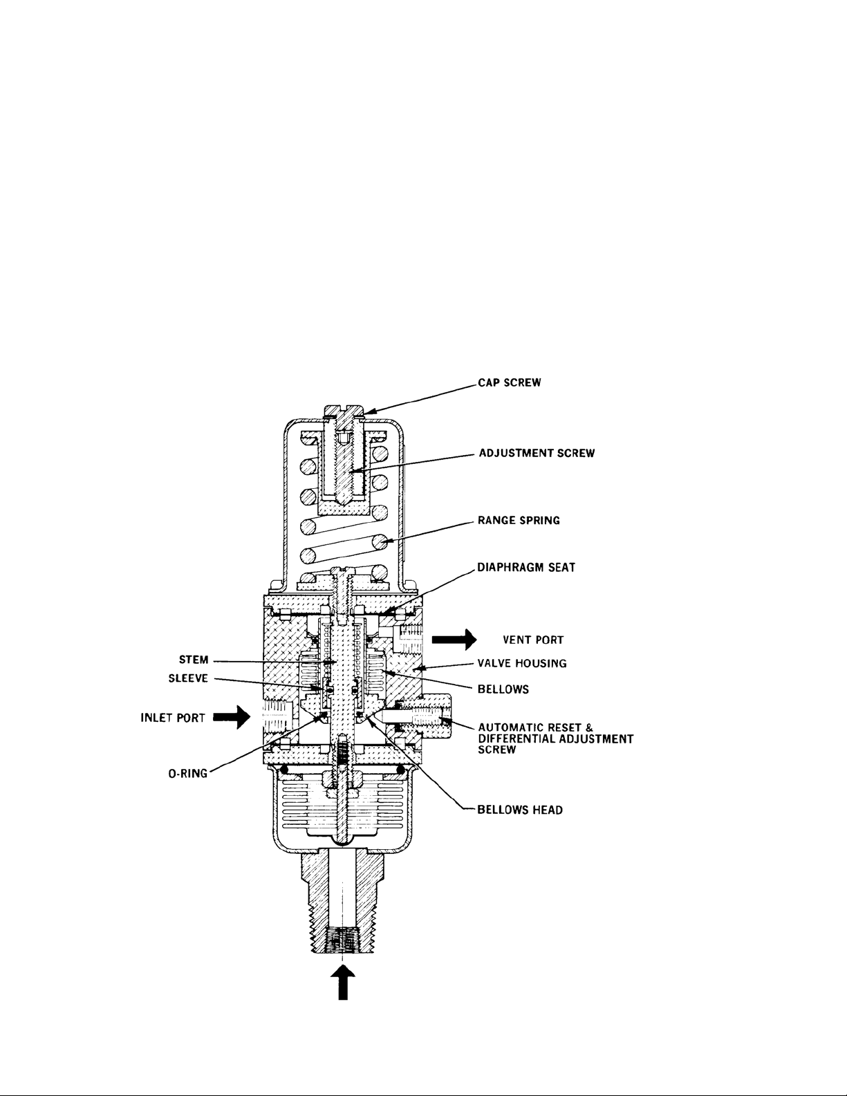
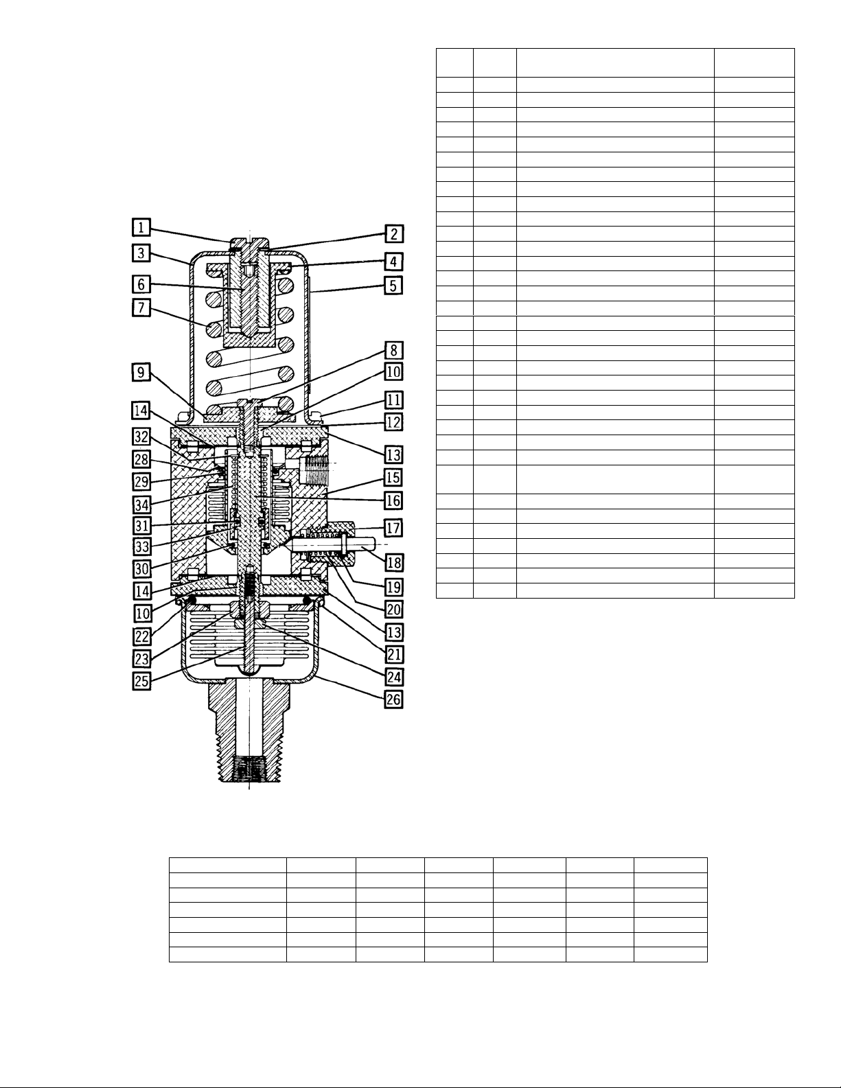
MAINTENANCE - See Figure 4
WARNING: USE CARE WHEN
DISASSEMBLING, SPRING FORCES PRESENT.
CAUTION: Do not subject O-rings, gasket, or
diaphragms to cleaning fluid, acetone, or any
halogenated hydrocarbons such as degrease liquids,
etc. Clean only with a soft, dry cloth. Metal parts can
be cleaned with a suitable solvent, and then dried
thoroughly before reassembly.
NOTE: Threads on screw (detail 8), diaphragm clamps,
spring housing screws (detail 11), bushing, and pressure
assembly screws (detail 21 should have Loctite Sealant
"H" or equivalent applied before reassembly. See * below.
Pressure Assembly
Remove four screws (detail 21) and O-ring (detail 22).
Replace defective pressure assembly, reassemble* and
recalibrate.
Bushing
To replace bushing O-ring (detail 19), remove bushing
and replace defective O-ring. Reassemble* unit and replace
in housing assembly. Recalibrate differential if unit is an
automatic reset model.
Housing Assembly and Stem
Remove cap screw and turn adjustment screw (detail 6)
counterclockwise to bring the range spring to free length.
Remove the four screws (detail 11), spring housing, spring
seat (detail 4), range spring and gasket. Remove the
pressure assembly as previously described. As applicable,
proceed with the Direct- or Reverse-Acting instructions
below.
Direct-Acting
Prevent the spring seat (detail 9) from rotating and back
the lock nut away (counterclockwise) from the nut several
turns. Preventing the spring seat (detail 9) from rotating,
remove the adjusting screw, nut, and lower flange.
Prevent the spring seat (detail 9) from rotating and
remove the exposed diaphragm clamp. Remove the
exposed diaphragm. Remove the stem by pulling the flange
from the valve housing.
To replace O-ring (detail 31) on stem, prevent spring
seat (detail 9) from rotating and remove screw (detail 8).
Prevent stem from rotating and remove spring seat (detail
9) and flange. Proceed with instructions designated Direct-
and Reverse-Acting below.
Reverse-Acting
Prevent the nut from rotating and remove the screw
(detail 8) and spring seat (detail 9). Remove the upper
flange.
Prevent the nut from rotating and remove the exposed
diaphragm clamp. Remove the exposed diaphragm. Remove
the stem by pulling the remaining flange from the valve
housing.
To replace O-ring (detail 31) on stem, prevent the nut
from rotating and back the lock nut away
(counterclockwise) from the nut several turns. Remove the
adjusting screw, nut, and flange. Proceed with instructions
designated Direct and Reverse-Acting below.
Direct- and Reverse-Acting
Remove remaining diaphragm clamp and diaphragm.
Remove retaining ring (detail 32,), spring (detail 34), and
sleeve. Remove defective O-ring (detail 31) and replace.
Reassemble sleeve, spring (detail 34) and retaining ring
(detail 32).
To replace O-ring (detail 29) in valve housing, remove
retaining ring (detail 28) and defective O-ring (detail 29).
Replace O-ring, then retaining ring.
To replace O-ring (detail 30) which seats against the
sleeve, remove the defective O-ring with a knife or other
sharp-pointed tool. Carefully remove any residue and clean
area from where O-ring was removed with a suitable
solvent. Dry thoroughly. Place a few drops of liquid Viton
(Pelmor Laboratories' PLV-2000 or equivalent) on the
seating area just cleaned. Take the replacement O-ring,
remove from it any dust, dirt or foreign matter, and bond it
to its seating area. Allow to cure for one or more hours.
With all O-rings, diaphragms, gaskets and defective
parts replaced, reassemble as follows:
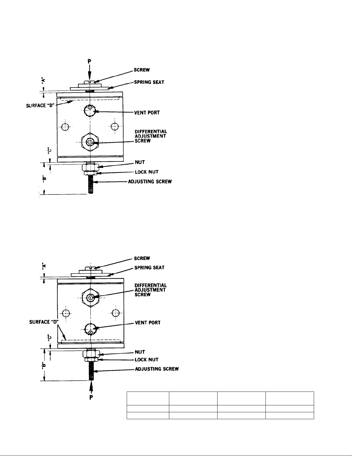
On models with automatic reset, turn differential
adjustment screw into bushing clockwise until small end of
bellows head is even with surface "D" - see Figure 3. (On
models with manual reset, the reset plunger will need to be
held depressed to obtain surface "D" contact as explained
below).
Replace stem, diaphragms, and diaphragm clamps*.
Tighten clamps hand tight. While holding each clamp with
a wrench, tighten approximately 1/4 turn more.
Reassemble* remaining parts as shown in figure 3.
On models with manual reset, depress the reset plunger
to maintain small end of bellows head with surface "D"
contact while obtaining the following dimensions - see
figure 3.
Apply approximately one pound force (4.45 N) by finger
at point "P." Turn spring seat to obtain dimension "A" - see
Table 3. Lock spring seat in place with screw*.
With a gage in place to hold dimension "A," adjust
adjusting screw to dimension "B" and nut to dimension "C"
- see Table 3. Lock both in place with lock nut as shown in
figure 3.
Release reset plunger on manual reset models and turn
differential adjustment screw counterclockwise
approximately 3/4 turn on auto reset models.
Reassemble* remaining parts and recalibrate sensor.
FIELD REVERSAL
To change the sensor from direct- to reverse-acting or
vice versa, remove the spring seat (detail 9), adjusting
screw, and nut from stem. Reset bellows head to surface
"D" as explained in the Housing Assembly and Stem
Maintenance section. Reassemble spring seat (detail 9),
adjusting screw, and nut on appropriate end of stem using
figure 3 as a guide. Reset dimensions "A," "B" and "C" and
reassemble as explained in the Housing Assembly and Stem
Maintenance instructions. Recalibrate sensor when
assembled.
This manual suits for next models
6
Table of contents
Other Robertshaw Accessories manuals