manuals.online logo
Brands
  1. Home
  2. •
  3. Brands
  4. •
  5. Robinson Willey
  6. •
  7. Gas Heater
  8. •
  9. Robinson Willey Warmplan XX series User manual

Robinson Willey Warmplan XX series User manual





ContactDetails

Pleasenotethatsomeofthecontactdetailson
thisPDFdocumentmaynotbecurrent.

Pleaseusethefollowingdetailsifyouneedto
contactus:

Telephone:08448793588
Email:[email protected]


TheHelpCentresectionofthiswebsitealsofeaturesawiderange
ofinformationwhichmaybeofusetoyouandisavailable24
hoursaday.Itincludes:

•Manualsandguidesdownloads
•Servicing
•Wheretobuyourproducts
•Literaturedownloads

www.robinsonwilley.co.uk/help
A division of GDC Group Ltd
Millbrook House Grange Drive Hedge End Southampton SO30 2DF
www.robinsonwilley.co.uk
Re
g
istered No: 1313016 En
g
land
VAT GB 287 1315 50004
EEE Producer Registration Number –
WEE/GE0057TS
Paper from sustainable sources
1
Instructions
for Installation and
Servicing
FOR USE IN G.B. & I.E. CAT I G20 at 20mbar
2H
CAT I G30/31 at 28/37mbar
3+
Warmplan XX
Series
AUTO - G C No. 35 694 56 MANUAL - G C No. 35 694 57
2
Robinson Willey No LP5
}
SECTION A - DESCRIPTION OF HEATER AND SPECIFICATION
The Warmplan XX Series Heater is a room sealed convector of the fan assisted type. Two fans are used, a
centrifugal fan which draws in air for combustion and evacuates the products of combustion, and a convection
fan which passes the air from the room over the heat exchanger. The combustion and convection air systems are
completely separate. The use of a fan to assist the flow of combustion air means that a small diameter flue can
be used instead of the large diameter flue necessary for natural flow heaters. The flue consists of two concentric
tubes, the outer one being used to draw in the combustion air and the inner to evacuate the flue products.
The Warmplan XX is designed to burn Natural and L.P. gases. The burnt gas passes from the combustion
chamber into a separate heat exchanger releasing heat which is taken up by the convection air and passed into
the room.
Ignition is by a continuous spark, igniting the main burner directly without the use of a pilot burner. A flame
rectification system is used to detect the presence of a flame. The heater does not have a low or turn down rate.
A safety system is incorporated which causes the heater to shut off if the flame fails for any reason. Protection is
provided against overheating caused by blockage of the outlet louvres or convection fan failure.
Warmplan XX Auto G.C. No. 35 694 56
This heater is fitted with a time clock and thermostat which permit complete flexibility in the selection of heating
programmes. Once the programme has been set on the clock and thermostat, an electronic system controls the
heater automatically.
Warmplan XX G.C. No. 35 694 57
This heater is identical to the Warmplan XX Auto except that it is not fitted with a time clock and must be switched
ON and OFF manually. After it has been switched ON, the thermostat is set to the position which gives the
required room temperature.
SPECIFICATION
Declaration of Efficiency
The efficiency of this appliance has been measured as specified in BS EN 1266 and the result is 80%. The gross
calorific value of the fuel has been used for this efficiency calculation. The test data from which it has been calculated
has been certified by Notified Body No.0087. The efficiency value may be used in the UK Government's Standard
Assessment Procedure (SAP) for energy rating of dwellings.
The above exceeds the minimum requirement of 72%.
Input 3.75kW (12/800Btu/h)
Output 3.00kW (10,200Btu/h)
Gas Supply Pressure Burner Pressure Injector
Natural Gas (20mbar) (8") 19.6±1mbar (7.8±0.4in w.g.) Robinson Willey No.N9
Butane (28mbar) (11.2") 27.5mbar (11")
Propane (37mbar) (14.8") 36.5mbar (14.6")
Electrical Supply 230V AC 50Hz
Rating 50 Watts
Gas Inlet 8mm nut & olive (NOTE: the thread for this nut is M14 x 1.5)
This appliance must be installed and serviced by a ‘Gas Safe’ registered engineer in accordance with these
instructions.
The installation must comply with the Gas Safety (Installation and Use) Regulations and be installed in
accordance with the rules in force.
The following special items are available:-
R.W. No. G.C. No.
Flue Guard 998749 203 823
Kit of parts to use when the hole
for the flue cannot be drilled 590300 203 736
Kit of parts for use with
combustible walls 598600 203 733
Descriptive technical information sheets for both kits are available on application.
WARNING: THIS APPLIANCE MUST BE EARTHED.
The guidance below should be followed, to comply with the terminal location specified by:-
BS 5440-1:2000 (Specification for installation and maintenance of flues).
B. Fanned draught
1. The flue terminal must not be less than 300mm (12") from any external obstructions such as
drainpipes, cables, bushes, eaves, projections or internal corners.
2. The Building Regulations require the terminal to be 300mm (12") measured vertically, from any
opening, i.e. window, door, ventilator, into the building. These regulations also require that where the
terminal is situated less than 2m (6'6") above a level to which people have access, a flue guard must
be fitted.
1. Inside the building the heater must be fixed to an external wall, observing the clearance distances in
Fig. 1 so that sufficient access is left for servicing. Note that if the heater is sited too high up the wall,
poor heat distribution will result.
2. If the heater is fitted below a shelf, a 25mm (1") gap should be left between shelf and heater and the
shelf should not project in front of the heater.
3. Curtains should clear the heater by 25mm.
4. Ensure that there is an adequate gas supply available.
5. Ensure that there is a suitable electrical supply available.
6. If the heater is to be fitted with a flue longer than 915mm (3ft) ensure that there is adequate clear
space in front of the heater for manoeuvring the assembly of heater and flue.
3
TERMINAL POSITION MINIMUM DISTANCE
A - Directly below, above or to the side of
an openable window or other opening e.g. air brick 300mm
B - Below gutters, soil pipes or drain pipes 75mm
C - Below eaves 200mm
D - Below balconies or car port roof 200mm
E - From vertical soil pipes or drain pipes 75mm
F - From internal or external corners 300mm
G - Above ground, roof or balcony level 300mm
H - From a surface facing a terminal 600mm
I - From a terminal facing a terminal 1200mm
J - From an opening in the car port (e.g. door, window) into dwelling 1200mm
K - Vertically from a terminal on the same wall 1500mm
L - Horizontally from a terminal on the same wall 300mm
Siting the Heater
Check the following points before deciding the position of the heater in a room.
Building Regulations also require that where the terminal is situated less than 2m (6'6") above a level to which
people have access, a flue guard must be fitted.
Preliminary Work
1. The carton contains, in addition to the heater and these instructions, a template, a flue gasket, screws
to fasten the flue to the heater and screws and plugs to fasten the heater to the wall.
2. Place the template on the wall in the required position, and mark the position of the flue hole. Remove
the template.
3. Using a suitable drill and masonry cutter fitted with pilot drill, drill a hole 65mm (2½") diameter
straight and level through the wall. Take care to prevent chipping of bricks on the outside face of the
wall. N.B. ON WALLS WITH COMBUSTIBLE INTERNAL CLADDING, REMOVE THE CLADDING
WITHIN 25mm (1") OF THE FLUE DUCTING.
4. Replace the template so that the flue position on the template is concentric with the hole just drilled,
level the top of the template and mark the position of the four fixing holes.
5. Drill the fixing holes 6mm (¼") diameter x 40mm (1½") deep and fit the wall plugs provided .
6. If the hole for the flue cannot be drilled, but must be cut with a chisel, a kit (No. 590300), which
provides a finishing plate for the outside face of the wall must be used. Alternatively, the wall can be
made up with cement to leave a hole 65mm (2½") diameter.
7. If the wall on which the heater is to be mounted is made of combustible material, another kit,
(No. 598600) which provides a wall liner and finishing plate, is available.
8. If the wall is less than 125mm (5") thick, it must be built up behind the heater to give an overall depth
of wall of at least 125mm (5").
Preparation of the Flue
Three standard lengths of flue are available. Each flue is packed in a carton together with a piece of sealing
tape:-
Long FX3 Suitable for walls from 355mm (14") to 510mm (20")
Medium FX2 " " " " 205mm ( 8") to 355mm ( 14")
Short FX1 " " " " 125mm ( 5") to 205mm ( 8")
Flues of lengths above 510mm (20") and up to 1525mm (60") are also approved for Natural Gas and two flues in
this range are available to special order. These Flues are:-
FX4 Suitable for walls from 510mm (20") to 865mm (34")
FX5 Suitable for walls from 865mm (34") to 1525mm (60")
For operation on L.P.G. flues up to 865mm (34") only are approved. That is:-
THE FX5 FLUE MUST NOT BE FITTED TO HEATERS OPERATING ON L.P.G.
All flues consist of two concentric tubes. Combustion air is drawn into the heater through the outer tube and flue
gases return through the inner one. Both tubes are tele-scopic. See Fig. 2.
1. Measure the length of the hole cut for the flue through the wall and add 6mm (1/4") to give dimension
A (Fig. 2).
2. Remove the self tapping screw from the outer tube of the flue and adjust the overall length of the
outer tube, measured between the outsides of the end flanges, to the flue length A.
3. Tape together temporarily the two parts of the outer tube to maintain the length A and drill a hole
3.5mm diameter (No. 29) through the hole for the self tapping screw. Re-fit the screw and wrap the
sealing tape, which is packed in the flue carton, round the joint.
4. It is NOT necessary to adjust the inner tube in any way. The 22mm (7/8") projection is automatically
maintained as the inner and outer tubes are fixed together.
5. In the case of flues of length 915mm (3ft) and above, the flue is set to length as detailed in paras. 1 to
3 above. No sealing tape is required. It is necessary to cut the flue tube using the gauge provided, to
the length of 22mm (7/8") as shown in Fig. 2. This dimension is important so it must be cut accurately
and burrs removed.
FIG. 1
4
5
Fitting the Heater
1. After lifting the heater from the carton, remove the protective plastic bag.
2. Put the outer case to one side to avoid damage. Remove the carton which contains the heater fixings
and lift the heater from its protective tray. The dressing strip can now be seen in the tray. It can be left
there for safety, but do not forget to remove It before the tray is destroyed.
3. Support the heater in a vertical position and screw the correctly adjusted flue and gasket to the back
plate of the heater using the screws provided. Ensure that the inner tube engages securely in the heat
exchanger without damaging the sealing tape ( Fig. 3). If the heater is laid face down, it must rest on
supports to prevent damage to the thermostat or clock control switch.
Screw flue assembly to heater
backplate and ensure inner
tube engages securely into heat
exchanger.
FIG. 3
4. Push the flue through the hole in the wall, support the heater so that its weight does not rest on the
flue, until the backplate fits against the wall. Fasten the heater in position with the four screws
provided. DO NOT support the heater on the convection fan.
5. From the outside, check that the air intake is not recessed in the wall and that the rubber sealing ring
is in place immediately behind the air intake flange. Do not render over the face of the rubber sealing
ring, should rendering be necessary.
6. If the flue terminal is situated in a place to which people have access and is less than 2m (6'6") from
the ground, the Building Regulations demand that a guard is fitted. A flue guard is available. Position
it on the wall concentric with the flue and fasten in position with the screws and plugs provided.
7. In the case of flues of length 915mm (3ft) and above, the procedure is generally as detailed in
paragraphs 1 to 6, but two people are required-one to support the heater and one to support and
guide the flue as the heater is pushed into position.
There are two methods of attaching the flue to the heater:–
(a) Attach the flue as detailed in paragraph 3 above, but with the flue and heater always supported.
(b) Push the flue into place leaving enough room between the wall and flue flange in which to turn a
screwdriver, then with the heater supported, screw the flue and gasket to the heater.
If, after installation, the flue passes through the space between two walls in a position where it is liable
to be damaged mechanically, then it should be protected by being boxed in. A timber framed and
covered construction is suitable.
4
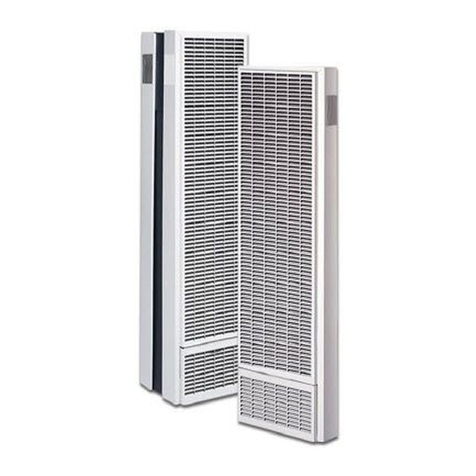
FIG. 2
Spigot
Gasket
Seal the flange to pipe joint,
ensuring the ‘Pin holes’ are
covered
6
Connection of Supplies
1. Extend the gas supply to a point convenient to the heater and connect to the solenoid valve at the
bottom left hand side of the heater. A union and gas tap must be incorporated to facilitate
maintenance. The inlet to the valve is 8mm nut & olive.
Note that the valve must be supported when the union is fitted.
2. Purge the system and test for gas soundness.
3 Provide an electrical supply socket, or fused spur nearby. Make sure that the live and neutral poles
are correctly phased. If phasing is reversed, the heater will not operate correctly.
A plug is already wired into the mains lead. If the mains lead is too long remove the plug and cut the
wire to length then follow the instructions below for rewiring the plug.
4. Free the mains cable from the heater. One end is already attached to the heater and has a mains
cable clamp fitted. Slacken the nut on the cable clamp, slide it in the slot in the support plate at the
bottom right hand side of the backplate and re-tighten the nut. The wires in the cable are coloured in
accordance with the following code:-
Green/yellow - Earth
Blue - Neutral
Brown - Live
If these colours do not correspond with the colours identifying the terminals of the plug which is being fitted,
proceed as follows:-
Connect the wire which is coloured green/yellow to the terminal marked with the letter E or by the Earth
Symbol or colour green.
Connect the wire which is coloured blue to the terminal marked with the letter N or coloured black.
Connect the wire which is coloured brown to the terminal which is marked with the letter L or coloured red.
If the plug is unmarked, or if in any doubt, consult a qualified electrician.
Two pin plugs must not be used.
If a fuse is fitted, it must have a 3 amp rating. See Fig. 4.
FIG. 4
7
START
Isolate appliance
and carry out:
A. Earth Continuity
check
Check Mains Vac
at appliance
terminal strip/block
Carry out:
D. Resistance to Earth
check
Electricity supply should
now be satisfactory
Carry out:
C. Polarity check
Has inlet flue blown?
Inlet wiring
faulty,
Rectify any
fault
Isolate appliance and carry
out:
B. Short circuit check
Rectify any fault including
replacing fuses as
necessary
YES
YES
NO
NO
FIG. 5
Preliminary Electrical System Checks (See figs. 5, 7 & 8)
A. Earth Continuity Check - appliance must be electrically disconnected - meter set on W (ohms) x 1
scale and adjust zero if necessary.
(a) Test leads from any appliance earth point to earth pin on plug - resistance should be less than
1 W (ohm).
If the resistance is greater than 1 W (ohm) check all earth wires for continuity and all contacts
clean and tight .
If resistance of earth is still greater than 1 W (ohm) then this should be reported to your
supervisor.
B. Short Circuit Check - appliance electrically disconnected, all switches ON (including stats)
(a) meter set on W (Ohms) x 1 scale.
Test leads from L to N in appliance terminal strip/block - if meter reads '0' then there is a short
circuit.
(b) meter set on W (ohms) x 100 scale.
Repeat test with leads from L to E. If meter reads less than ¥ (infinity) there is a fault.
NOTE:- should it be found that the fuse has failed but no fault is indicated-a detailed continuity check (i.e. by
disconnecting and checking each component) is required to trace the faulty component. It is possible that a
fault could occur as a result of local burning/arcing but no fault could be found under test. However, a detailed
visual inspection should reveal evidence of burning around the fault.
C. Polarity Check
Appliance connected to mains supply and meter set on 300 Vac scale. Test at appliance terminal strip:-
(a) Test leads from L to N - meter reads approx. 230 Vac.
(b) Test leads from L to E - meter reads approx. 230 Vac.
(c) Test leads from N to E - meter reads from 0 - 15 Vac*
Thus the terminal marked L is the live terminal. If the low* Vac reading is given on terminals other than N to E
there is an electrical fault).
8
Repeat the test at the appliance plug/inlet spur to check the wiring system up to the appliance and
rectify any fault. If necessary repeat the test at the supply system socket/ spur - if the fault also occurs
at this stage then there is a house system fault which requires attention by the Electrical Authority.
The customer should be warned not to use the appliance until this examination has been carried out.
D. Resistance to Earth Check
Appliance must be disconnected from mains supply and meter set on W (ohms) x 100 scale. All
switches, including stats, ON - Test leads from L to E - if meter reads other than infinity (¥) there is a
fault which should be isolated. A detailed continuity check is required to trace the faulty component.
IMPORTANT This series of checks are the first electrical checks to be carried out during a fault
finding procedure. On completion of the service/fault finding task which has required
the breaking and remaking of electrical connections then the checks A. Earth
Continuity, C. Polarity and D. Resistance to earth - must be repeated.
Checking the Heater Operation
1. Switch on the gas and electricity supplies. Purge the gas supply pipe if necessary. If the heater is a
Warmplan XX Auto, make sure that the clock is in the ON position. Turn the control knob clockwise to
position 6. The amber lamp will come on indicating that the ignition cycle has started. After about 20
seconds the red lamp will come on. The heater is now operating. Check that the heater operates as
detailed in the section, NORMAL OPERATION, of part D of this booklet. If the supply pipe is not
completely purged, the heater may 'lock out' once or twice without ignition. If the heater locks out
after ignition, check the polarity of the electrical supply.
2. Check the gas pressure at the pressure test point. See technical specification for the correct
pressure. If the pressure is not correct, check the gas pressure at the meter and supply pipe for
blockage. Refit air guide and connectors after checking.
3. The flame can be seen in the window on the right hand side of the heat exchanger. It is normally blue,
but some yellowing is possible when operating on butane gas.
WHEN USING BUTANE/PROPANE
When the appliance is converted for use with Butane or Propane the burner injector is fitted with a
brass extension, to facilitate ignition on Propane gas. (See diagram below). When operating on
BUTANE GAS, if it is considered that the flame is excessively yellow, the brass extension should be
REMOVED. To obtain access to the injector, see Servicing Notes headed 'Injector'.
INJECTOR EXTENSION (BRASS 998022)
4. Fit the dressing strip and case, removing, first of all, the two screws at the sides of the case which
fasten the dressing strip. Tighten all four screws.
9
MAKE SURE THE USER KNOWS THAT:
1. The gas tap and electricity supply must be turned on before the heater will operate.
2. The heater will light automatically when the control is turned beyond the position corresponding to
the room temperature.
3. The heater switches ON and OFF automatically to maintain the selected heat level.
4. The gas cock below the heater should be left ON even when the heater is not in use.
5. Neither clothes nor material should be draped over the louvres, nor should furniture be placed closer
than 250mm (12") from the heater, although a safety device is fitted to overcome the possibility of
overheating.
6. Children should be prevented from posting letters, pencils, knitting needles or similar items through
the louvres.
7. The flue terminal should not be blocked in any way.
10
SEQUENCE
W = WHITE P = PURPLE EVENT DISPLAY
Thermostat call for heat Amber light only ignition/reset
O/B = ORANGE/BLACK Y/G = YELLOW/GREEN Combustion fan runs
ignition sequence starts
OR = ORANGE BL = BLUE When the flame is detected convection
fan starts and red light comes on as well
YL = YELLOW BR = BROWN Overheat limit switch operates Red light goes out
Amber light stays on
Gas fails (lock out) Red light goes out
Amber light stays on
Power fails Both lights go out
Will start ignition sequence
when power is returned
Clock or Thermostat satisfied Both lights go out
MANUAL
- WIRING DIAGRAM
11
SEQUENCE
W = WHITE P = PURPLE EVENT DISPLAY
Clock and thermostat call for heat Amber light only ignition/reset
O/B = ORANGE/BLACK Y/G = YELLOW/GREEN Combustion fan runs
ignition sequence starts
OR = ORANGE BL = BLUE When the flame is detected convection
fan starts and red light comes on as well
YL = YELLOW BR = BROWN Overheat limit switch operates Red light goes out
Amber light stays on
Gas fails (lock out) Red light goes out
Amber light stays on
Power fails Both lights go out
Will start ignition sequence
when power is returned
Clock or Thermostat satisfied Both lights go out
AUTO
GI
- WIRIN D AGRAM
12
WARMPLAN AUTO
FUNCTIONAL FLOW
13
WARMPLAN MANUAL
FUNCTIONAL FLOW
14
SECTION C - SERVICING
General Notes
Before removing the case to carry out any servicing or maintenance operation, always turn off the gas and
electrical supplies.
A qualified person can operate the heater with the case removed, provided that due care is exercised. Do not
attempt to remove components with the supplies switched on.
After removing or replacing any gas carrying component, always test for gas soundness.
Make sure all screws and washers are replaced and firmly tightened. Always use pliers to pull off tag
connectors.
Refer to figs. 5, 6, 7, 8, 9 and 10.
Servicing the heater is recommended once a year. Servicing consists of removing dust from the fan rotors
and the heater generally, cleaning the burner and checking for gas soundness and checking the operation of
the heater.
Removal of the outer case.
1. Turn off gas and electrical supplies.
2. Remove the two screws located at the bottom of the dressing strip and slacken the two screws located
behind the top louvre, Fig. 1. Pull the case away from the bottom of the heater and lift the case off the
top screws. remove the dressing strip.
3. To replace, keep the bottom of the case away from the heater and lower it so that the locating brackets
inside the top of the case drop over the top screws. Push the bottom of the case into position and
replace the dressing strip and side screws. Tighten all screws.
With the case removed, any part of the heater can be serviced or replaced as described in the following notes:–
Control Board
1. Disconnect the wires from the over heat limit switch.
2. Pull off the 10 way Molex connector from the mounting pins on the control board.
3. Disconnect the spark located at the lower end of the control board.
4. Carefully remove the control board by easing the four corners of the "stand off pins".
5. Refit in the reverse manner.
15
Overheat Switch
1. Pull off the tag connectors and remove the two screws holding the mounting bracket.
2. Lift out the switch assembly, noting that the switch is fitted with its blade uppermost.
3. Unfasten the switch from the plate and replace it with the new one, taking care not to touch the switch
blade.
4. Replace the switch assembly and make the connections.
Indicating Lamps
1. Pull off the control knob and remove the four screws holding the control panel in position .
2. Draw the panel away from the mounting bracket and pull off the tag connectors from the lamp.
3. Remove and replace the lamp. Refit the tag connectors.
4. Replace the control panel and control knob.
Thermostat
1. Remove the control panel and tag connectors to both lamps as in the last section.
2. Pull off the tag connectors visible on the thermostat assembly.
3. Straighten the two retaining clips (using pliers or similar) and release the capillary tube and phial.
4. Remove the nut and washer on the thermostat spindle and pull the thermostat assembly from the
control bracket.
5. Fit the new thermostat assembly, reversing the operations in instructions 1 to 4.
Time Clock (WARMPLAN XX AUTO)
1. Pull off the control knob and remove the clock cover, pulling it away from the control panel .
2. Remove the four screws holding the control panel to the mounting bracket and ease off the panel.
3. Pull off the terminal connections from the timer.
4. Remove the timer from the panel by releasing the clips on
the reverse side. Refer to Fig. 10A.
5. Fit the new timer and slide the clips to secure it on the
reverse side of the panel.
6. Refit the push on tags to the timer.
7. Replace the control panels, control knob and timer cover.
Convection Fan FIG. 10A
1. Disconnect the fan wires from the main terminal block and the earth connection from the motor.
2. Remove the screw, washer and spacing collar from each end of the fan and pull the fan from the back
plate.
16
3. Fit the new fan over the bosses on the back plate; fit the spacing collar and replace the screws and
washers. Make sure that the air guide on the fan fits behind the front division sheet.
4 Remake the electrical connections.
5. To clean the fan, brush the blades with a soft brush until all the dust is removed. The fan does not
need lubricating.
Combustion Fan
1. Remove the front division sheet by removing four screws.
2. Disconnect the fan wires from the main terminal block and the earth connection from the fan.
3. Remove the two screws and washers holding the fan to the heat exchanger and pull off the fan and its
rubber connecting duct.
4. Fit the rubber duct to the new fan. Always fit a new gasket when the fan has been removed. For ease
of assembly, the new gasket may be secured to the flange of the fan with a few spots of contact
adhesive.
5. Fit the fan to the heat exchanger, making sure that the rubber duct fits securely round the plunged
hole in the backplate and that the sealing gasket is not damaged. Re-fit the screws and washers.
6. Remake the electrical connections
7. To clean the fan, brush the rotor blades with a soft brush until all the dust is removed. The fan does
not need lubricating.
Solenoid Valves
1. Pull off tag connector from the spark electrode. Remove two screws and washers from the air guide
and remove the air guide.
2. Disconnect the gas inlet connection to the heater.
3. Remove the six wire connectors to the solenoid valve assembly (Note their positions).
4. Disconnect the tubing nut connection on the burner supply pipe.
5. Remove the two screws and washers fixing the burner supply tube to the burner mounting plate.
Remove the valve assembly and burner supply tube out from the valve support bracket and away
from the heater.
6. Fit the new valve assembly to the heater using the new gasket provided.
7. Resecure the valve assembly using the existing screws and washers. Tighten the inlet gas connection
and the tubing nut.
8. Refit the six wire connections, Their positions can be seen on the wiring diagram provided in these
instructions.
9. Refit the air guide and reconnect the spark lead to its electrode (the one with the round pin).
10. Reconnect the gas and electrical supplies.
17
Electrode Assembly and Spark Gap
1. Pull off the tag connectors from the electrodes. Remove the two screws from the air guide. Remove
the air guide from the heater.
2. Remove the three screws holding the electrode assembly and gasket.
3. Before fitting a new electrode assembly check that the spark gap is between 3mm and 4mm (1/8." to
3/16") as shown in Fig. 11.
4. Fit the electrode assembly and gasket, replacing the screws and washers and refit the air guide.
Replace the tag connectors, the round connector to the spark electrode.
5. The detection electrode is located on the right side of the combustion chamber (just below the
viewing glass). To remove, pull off the tag connector then remove the single screw fixing it to the
combustion chamber side. Withdraw the electrode away from the heater.
6. Refit in the reverse manner.
Burner
1. Disconnect the gas supply inlet connection and electrical connections to the solenoid valve and
electrode assembly. Remove the air guide as detailed in paragraph 1 of the last section. Remove the
solenoid valve assembly.
2. Remove the four screws and washers in the burner mounting plate and withdraw the burner from the
heat exchanger. The burner can now be cleaned or examined.
3. If the burner is to be replaced, remove the two screws and washers holding the gas supply tube and
the lower two of the three holding the electrode assembly. Remove the burner. Fit the new one and
refit all four screws and washers.
4. Replace the burner and solenoid valve assembly using a new gasket. To assist re-assembly the
gasket may be held in position with a few spots of contact adhesive. Replace the screws and washers
and remake the gas connection. Replace the air guide, then replace the electrode leads.
Injector
1. Pull off the tag connectors from the electrodes. Remove the two screws from the air guide. Remove
the air guide from the heater.
2. Disconnect the gas supply inlet connection and electrical connections to the solenoid valve. Remove
the two screws and washers holding the gas supply pipe to the burner mounting plate and withdraw
the valve assembly from the heater.
3. Unscrew the injector, clean and replace or change to the size required for another gas.
4. Refit the supply pipe, fitting a new gasket and refitting the screws and washers. Remake the gas
connection. Replace the air guide and electrode connections.
SECTION D - FAULT FINDING
For accurate fault finding, it is important to understand how the heater operates so that faulty operation can
be judged against the normal pattern of operation.
Normal Operation
If the heater is working correctly, the following sequence of events should occur after the heater has been
switched on (See user's Instructions).
1. The amber lamp comes on and the combustion fan starts. Check by touching the motor. A slight
vibration should be felt if the fan is running. Also, air can be detected leaving the flue terminal.
2. During the next 20 - 30 seconds, the combustion fan alone operates, purging the heat exchanger with
fresh air. This is called the purge period.
3. At the end of this period, the red lamp comes on as well. The combustion fan continues to run and
the following components commence operation.
The convection fan: This can be checked visually.
18
The spark generator: a buzzing noise is heard and sparks can be seen through the window at the
right hand side of the heat exchanger.
4. The gas at the burner is ignited. A circuit on the control board detects the flame and maintains the
heater in the normal operating condition. The flame can be observed in the window at the right hand
side of the outer case. The detection current should be greater than 3uA. The detection current is
measured by removing the connection from the detection electrode and inserting an ammeter with a
minimum f.s.d. of 10 uA. This must be done before the heater is switched on.
5. The heater continues to operate and is switched on and off automatically in accordance with the
heating programme set on the clock and thermostat. Note that the heater operates at full rate when
heat is required and is switched off when heat is not required. There is no low or by-pass rate.
Operation in Fault Conditions
1. If, in item 4 of Normal Operation above, the gas is not ignited, the spark generator will continue to
operate for approximately 9 seconds. This time is called the ignition period. At the end of the ignition
period the circuit on the control board causes the valve to close and switches off the convection fan
and spark generator. The red lamp goes out and the amber lamp remains on. This condition is known
as the 'lock-out' condition. The heater cannot be re-lit until the electrical supply is broken and re-
made, by turning the control knob to the OFF position or operating the override switch.
2. If, while the heater is running normally, the flame fails because of:-
Combustion air failure
Gas failure
Overheat switch operation
The heater will revert to the 'lock out' condition. If, when the heater is switched on the control board
has a fault which simulates the presence of a flame at the burner, the heater will revert immediately to
the 'lock out' condition without attempting to light.
Possible Faults
When examining the heater for faults, switch it off, and then switch it back on. Observe what happens and
compare with the pattern of operation noted above. A test instrument for checking voltage and electrical
continuity is very useful. If a control board fault is suspected, check by substituting a spare control board.
The following are possible fault conditions:-
Fault Check
1. Combustion fan does not start Main switch and fuse is fitted. Clock is in an 'On' period
(Warmplan XX Auto). Thermostat setting is above room
temperature.
Connections to main switch on thermostat.
Combustion fan and connections.
2. Combustion fan starts but purge Connections from main terminal block to control board
period does not end. terminal block.
Possible control board fault.
3. Heater reverts to lock out condition Gas supply. Purge gas line on a newly installed heater.
without ignition after normal Solenoid valve operation and electrical connections.
purge and ignition periods. Injector for blockage.
Spark electrode gap and electrode setting in relation to the
flame port in the burner.
19
4. As 3, but no spark visible Spark availability at electrode during spark period.
during ignition period. Remove the spark lead from the electrode, hold with
insulated pliers 3mm from earthed metal. If a spark is
present examine the spark electrode for damage to
insulation and check the spark gap. If no spark is present,
check the continuity of the overheat switch and
connections. If satisfactory the control board is faulty.
5. Heater lights but goes to lock out Detection electrode and lead for short to earth. Gas supply
condition. for continuity.
Air supply blockage.
Freedom of combustion fan rotor.
Possible control board fault.
Polarity of electrical supply.
SHORT PARTS LIST
Key
No.
G.C.
No. Part No.
off RW No. Key
No.
G.C.
No. Part No.
off RW No.
Convection Fan Assembly, ITT
13LL RMM/Wx 1596
Combustion Fan: Torin DSA 300
101/2286
Gasket: Combustion Fan
Air Intake Duct
Gasket: Burner Mounting Plate
Injector: (Natural Gas) RW N.9
Electrode Assembly including
Key No. 40
Gasket: Electrode
Solenoid Valve
Gasket: Injector Holder
Pressure Test Nipple Screw
Printed Circuit Board
Electrode
389 283
389 282
203 796
203 797
393 344
203 798
393 570
203 799
203 750
400 001
991 470
204 080
17
26
28
29
32
35
39
40
42A
49
50
65
39A
1
1
1
1
1
1
1
1
1
1
1
1
1
1
71
72
77
78
79A
80
81
82
83
84
85
87
94
99
Control Panel ( )
Overheat Limit Switch Otter V10c
Timer Unit - Sangamo 918801
(WARMPLAN XX AUTO)
Timer Clock Cover
( AUTO)
Thermostat Ranco CA6P1916
Control Panel ( AUTO)
Red Neon Indicator
Amber Neon Indicator
Control Knob
Outer Case Assembly (not illustrated)
Dressing Strip
Bezel for Viewing Window
Gasket - Flue
Cable Clamp
WARMPLAN XX
WARMPLAN XX
WARMPLAN XX
203 811
393 346
383 561
203 814
385 799
203 815
203 816
203 817
203 818
203 819
203 820
203 821
202 915
203 825
1
1
1
1
1
1
1
1
1
1
1
1
1
1
990965
820953
822125
822126
820954
997914
820956
820955
998786
998575
998982
820968
930611
820752
1
998477
998569
998788
998797
998789
998483
998578
998791
987451
999234
999542
991470
820046
42A
65
17
71
79A
94
40
28
49 29
85
26
80
83
87
50 99
35
72
39
81/82
77
32 39A 78

This manual suits for next models

1

Other Robinson Willey Gas Heater manuals

Robinson Willey Bantam Ecotherm User guide

Robinson Willey

Robinson Willey Bantam Ecotherm User guide

Robinson Willey FIREGEM VISA HIGHLINE SUPER DELUXE A86017 Operation instructions

Robinson Willey

Robinson Willey FIREGEM VISA HIGHLINE SUPER DELUXE A86017 Operation instructions

Popular Gas Heater manuals by other brands

MALTEC GAS-2500Wt instruction manual

MALTEC

MALTEC GAS-2500Wt instruction manual

Desa VN10TA OWNER'S OPERATION AND INSTALLATION MANUAL

Desa

Desa VN10TA OWNER'S OPERATION AND INSTALLATION MANUAL

Bromic Heating PLATINUM 300 BURNER Service manual

Bromic Heating

Bromic Heating PLATINUM 300 BURNER Service manual

Seeley GDH Series Installation, Startup, Operation, Service & Maintenance Manual

Seeley

Seeley GDH Series Installation, Startup, Operation, Service & Maintenance Manual

Detroit Radiant Products UH-30 Installation, operation, maintenance and parts

Detroit Radiant Products

Detroit Radiant Products UH-30 Installation, operation, maintenance and parts

Hargrove AKXRG5/8CPCNG Installation and operation guide

Hargrove

Hargrove AKXRG5/8CPCNG Installation and operation guide

Monessen Hearth DST30 Installation and operating instructions

Monessen Hearth

Monessen Hearth DST30 Installation and operating instructions

Vermont Castings Radiance RADVT Series Installation & operating manual

Vermont Castings

Vermont Castings Radiance RADVT Series Installation & operating manual

FMI VULC24ND OWNER'S OPERATION AND INSTALLATION MANUAL

FMI

FMI VULC24ND OWNER'S OPERATION AND INSTALLATION MANUAL

Powrmatic LNVx Series User, installation and servicing instructions

Powrmatic

Powrmatic LNVx Series User, installation and servicing instructions

Gude GHS 4200 PIEZO Translation of the original instructions

Gude

Gude GHS 4200 PIEZO Translation of the original instructions

Desa INTERNATIONAL UNVENTED (VENT-FREE) GAS LOG... OWNER'S OPERATION AND INSTALLATION MANUAL

Desa

Desa INTERNATIONAL UNVENTED (VENT-FREE) GAS LOG... OWNER'S OPERATION AND INSTALLATION MANUAL

White Mountain Hearth VFP32FP20LN-1 Installation instructions and owner's manual

White Mountain Hearth

White Mountain Hearth VFP32FP20LN-1 Installation instructions and owner's manual

White Mountain Hearth LS-18H-1 Installation instructions and owner's manual

White Mountain Hearth

White Mountain Hearth LS-18H-1 Installation instructions and owner's manual

Vassilias R-024 instruction manual

Vassilias

Vassilias R-024 instruction manual

Sure Heat RVT-18 Installation and operating instrictions

Sure Heat

Sure Heat RVT-18 Installation and operating instrictions

Comfort Glow CGP20TB OWNER'S OPERATION AND INSTALLATION MANUAL

Comfort Glow

Comfort Glow CGP20TB OWNER'S OPERATION AND INSTALLATION MANUAL

Blumfeldt Andora manual

Blumfeldt

Blumfeldt Andora manual

manuals.online logo
manuals.online logoBrands
  • About & Mission
  • Contact us
  • Privacy Policy
  • Terms and Conditions

Copyright 2025 Manuals.Online. All Rights Reserved.