RoboLabs RoboFryBox One User manual

RoboFryBox One
Deep-fat fryer
User manual
Read this manual before use!
PDF version of this manual is available on www.robolabs.pro

Safety requirements
DO NOT operate without oil!
DO NOT operate with water!
Burn hazard! Hot oil!
Only instructed personnel is allowed to oper-
ate the equipment!
2

Contents
1 Overview 5
1.1 Technical specifications . . . . . . . . . . . . . . . . . . . . 5
1.2 Deliveryset........................... 5
1.3 Assembling ........................... 5
1.4 Ambient requirements . . . . . . . . . . . . . . . . . . . . . 6
1.5 Power requirements . . . . . . . . . . . . . . . . . . . . . . . 6
1.6 Design.............................. 7
1.6.1 Main components . . . . . . . . . . . . . . . . . . . . 7
1.6.2 Controlpanel...................... 7
1.6.3 Lightbox ........................ 8
1.6.4 Airfilter......................... 8
1.6.5 Low oil and water detection . . . . . . . . . . . . . . 8
2 Intended use 9
2.1 Normal operation order . . . . . . . . . . . . . . . . . . . . 9
2.2 Shuttingdown ......................... 10
2.3 Addingoil............................ 10
2.4 Changingoil .......................... 10
2.5 Water in oil (Err4) . . . . . . . . . . . . . . . . . . . . . . . 11
2.6 Oil temperature adjustment . . . . . . . . . . . . . . . . . . 11
2.7 Program timers adjustment . . . . . . . . . . . . . . . . . . 11
3 Cleaning and maintenance 12
3.1 Cleaning instructions . . . . . . . . . . . . . . . . . . . . . . 12
3.2 Filters replacement . . . . . . . . . . . . . . . . . . . . . . . 14
4 Transportation & storage 14
5 Quality control check 15
6 Warranty obligations 16
7 Manufacturer details 16
3

8 Technical service 17
8.1 Errorcodes ........................... 17
8.2 Setupmode........................... 18
8.2.1 Basket operation check . . . . . . . . . . . . . . . . . 18
8.2.2 Fine adjustment . . . . . . . . . . . . . . . . . . . . 18
8.3 Electric components layout . . . . . . . . . . . . . . . . . . 20
4

1 Overview
RoboFryBox One is a deep fat fryer (hereinafter "unit" or "machine") in-
tended for cooking various food in deep fat. The machine is used at public
catering facilities as standalone unit, or as a part of processing line. Not
for household use.
1.1 Technical specifications
Temperature adjustment range +90–220◦C
Operating oil volume 8 liters
Product load up to 500 g per basket
Heat up time not more than 20 min
Rated voltage 1P 230 V AC
Rated frequency 50 Hz
Rated power 3300 W
Net weight 50 kg
Dimensions (LxWxH) 350x545x820 mm
1.2 Delivery set
Unit 1 pc
Leg 4 pcs
Deflector 1 pc
Documentation 1 set
1.3 Assembling
1. Carefully unpack the machine, check delivery set and remove protec-
tive film from all surfaces.
2. Mount the legs and leg toes.
3. Put the machine on even flat surface.
4. Insert deflector in the door, under the load tray.
5

1.4 Ambient requirements
All items and surfaces close to the machine must be made of non-flammable
materials, or have non-flammable coatings. The equipment must be oper-
ated at the ambient temperature from +5◦to +40◦C and relative humidity
not more than 45% at 40◦C. The temperature decreasing related to RH in-
creasing, for example, 90% of RH at 20◦C. Altitude above sea level should
not exceed 1000 m.
1.5 Power requirements
Power outlet MUST have grounding contact!
If supply cord damaged, it must be replaced
by manufacturer, service agent, or qualified
persons in order to avoid hazard!
Connections must be done by qualified electri-
cian ONLY!
Use IEC 60309 2P+PE 16 A plug:
Equipotential bonding wire (up to 10 mm2) shall be con-
nected to screw terminal marked with IEC 5021 sign:
6

1.6 Design
1.6.1 Main components
Main components of the machine are the following: 1 – Door; 2 – Latch;
3 – Light box; 4 – Control panel; 5 – Loading tray; 6 – Deflector; 7 – Leg;
8 – Paper/carbon filter assembly; 9 – Grease filter; 10 – Oil tank; 11 –
Basket; 12 – Heating element; 13 – Drain valve:
1.6.2 Control panel
Control panel has the following items: 1 – ON/OFF button; 2 – 4-digit
display; 3 – program buttons:
7

1.6.3 Light box
Light box media can be easily changed. To change the media, first, slide
the door upper edge (that is held by magnet locks), and second, remove
the media:
1.6.4 Air filter
Unit has 3-stage air-filter, so no special exhausting hood is needed. First
stage is a grease filter, second stage is a paper HEPA filter, and third stage
is a carbon filter. Up to 98% of smallest particles less than 0,3 micron are
retained.
1.6.5 Low oil and water detection
The machine can detect low oil and water in oil. If oil is low, then the
machine will cut off the power supplied to the heaters and notify the op-
erator. If considerable amount of water presents in the oil, then machine
will also cuts off the power supplied to the heaters and notify the operator.
8

2 Intended use
2.1 Normal operation order
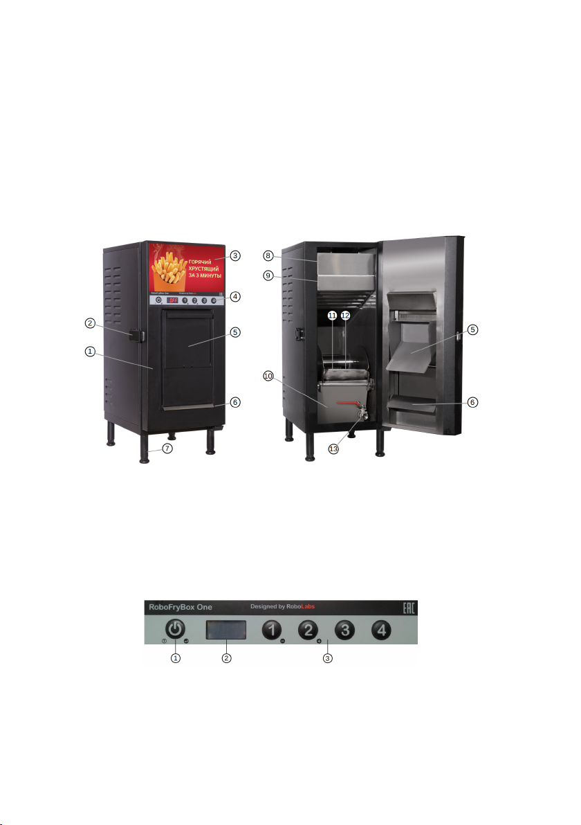
Make sure that machine is assembled, and all components are in its place
and oil drain valve is closed. Fill frying tank with oil up to the mark (8
liters), set the basket into dumping mechanism, and latch the door. Put a
suitable container for ready made product in front of the machine, under
the loading tray, it may be GN container, for example. When the machine
is turned off, light box is not lit, and display shows "OFF" message.
Press ON/OFF button to turn the machine on. The basket will be re-
turned to lower position, oil is started to be heated (by default to 180◦C);
ventilation and backlight are on. Heating progress is to be visualized on the
display. In the beginning of heating process, display shows four blinking
letters: HHHH. While temperature is rising up, there are less Hletters
blinking. Once the set point is reached, display shows the temperature
set value (180 for example). The machine is now ready for operation. To
prepare a portion of product, do the following:
1. Open the loading tray and put the product in the tray (not more
than 500 g per batch).
2. Close the tray.
3. Press a program button.
4. Wait until the product is being discharged automatically.
DO NOT open the tray while product is being
cooked!
Each program button corresponds to a timer that defines the product
residence time. Timers are adjustable, so it is possible to tailor the ma-
chine for virtually any product.
9

2.2 Shutting down
To end the operation, press ON/OFF button, the lightbox and the heater
are turned off. After turning off, ventilation operates for 5 minutes more,
and then automatically is turned off.
2.3 Adding oil
If "OIL" message appears on the display, it means that the machine has
detected low oil level. Do the following:
1. Turn the machine off.
2. Close loading tray
3. Open the door
4. Carefully pour oil into the frying pan up to the MAX mark.
5. Close the door
6. Turn the machine on.
2.4 Changing oil
The same load of oil can be used for certain time, which depends on the
product used, settings, and other factors. It is recommended to use special
tool or testing strips to find out when oil should be changed. To change
the oil, daily cleaning procedures must be performed, see Technical Main-
tenance section.
10

2.5 Water in oil (Err4)
Err4 message means that water in oil protection system was tripped. This
can happen either if there is water in oil, or if the machine has been turned
on with oil that was already warm, about 100◦C. To fix the error, do the
following:
1. Turn the machine off and turn on again. If the message is still here,
proceed to the next step.
2. Turn the machine off and drain the oil. Make sure there is no water
in the oil. Fill the tank with oil, and turn the machine on.
2.6 Oil temperature adjustment
1. Turn the machine off.
2. Press and hold ON/OFF button until Pr appears on the display,
then release the button.
3. Press ON/OFF button again, Pr-C appears on the display. Press
button #1 to decrease, or button #2 to increase the value. By default
the temperature is 180 ◦C.
4. The machine automatically returns back to standby mode after 10
sec of idle.
2.7 Program timers adjustment
1. If machine is on, turn it off by pressing ON/OFF button.
2. Press and hold ON/OFF button for 3 seconds, Pr appears on the
display.
3. Choose a program (buttons #1 to #4).
4. Set the time, by pressing buttons #1 (decrease) or #2 (increase).
11

5. Press ON/OFF button to save the new value.
6. To set another timer, repeat steps 3 to 5.
7. The machine automatically returns back to standby mode after 10
sec of idle.
3 Cleaning and maintenance
ALWAYS unplug before cleaning!
DO NOT use excessive water for cleaning!
DO NOT use aggressive solutions for cleaning!
DO NOT use sharp tools or items for cleaning!
Wait until oil is cooled down!
The purpose of cleaning and maintenance is to keep the machine operable
during the entire service life and to meet hygiene requirements.
3.1 Cleaning instructions
In the end of a day do the following:
1. Let the oil to cool down.
2. Attach oil drain hose to the valve, get ready a drainage container,
and put free end of the hose into container.
12

3. Open the valve and wait until oil is drained to the container.
4. Close the valve.
5. Take out the loading tray assembly, and detach tray and deflector
(Fig.1).
6. Take out the basket (Fig.2).
7. Lift up the heaters assembly until it is locked in upper position (see
Fig.3). To unlock the heater, pull it up, and pull up the pin on the
left side of the chamber, and then put the heater down.
8. Take out the frying tank. Pour the oil remains to the drainage con-
tainer (see Fig.4).
9. Take out paper/carbon filter assembly (see Fig.5). DO NOT wash
or soak the filters!
10. Take out the grease filter (see Fig.6).
11. Thoroughly wash basket, tank, heaters assembly, internal surfaces
of the chamber, grease filter, loading tray and deflector. Use warm
water and mild detergent suitable for stainless steel.
12. Wipe dry immediately.
Fig.1 Fig.2
13

Fig.5 Fig.6
Fig.3 Fig.4
3.2 Filters replacement
Change paper filter every 2–3 months, carbon filter — every 4–6 months.
Depending on intensity of machine operation, the period may vary.
4 Transportation & storage
The equipment may be transported by any kind of covered vehicle, in
accordance with transportation rules for this kind of vehicle. Ambient
temperature during the transportation and storage must be between mi-
nus 25◦C and +55◦C.
14

5 Quality control check
——————————————– ——————————————–
Product name Serial #
The equipment is made with accordance to mandatory
requirements of the state standards, actual technical
documentation, and approved for use.
QC Engineer
STAMP HERE
——————————————– ——————————————–
Signature Full name
——————————————–
DD.MM.YYYY
Actuator factory parameters:
A1 —
A2 —
A3 —
A4 —
15

6 Warranty obligations
The manufacturer guarantees trouble-free operation of the equipment dur-
ing 12 months from the date of receiving the equipment by a dealer (in
accordance with transport documentation); or, in case of purchase directly
through RoboLabs LLC, from the date of purchase, given that terms of
using, transportation, and storage are met.
The warranty repair is performed upon presentation of this manual and
filled warranty card with the seller’s seal and the date of sale. Technical
specifications of the equipment can be changed by manufacturer at any
time due to improvements and/or other reasons. Technical specifications
stated in this document are intended to act as a reference point, which is
necessary to evaluate suitability of the equipment for the customer’s needs,
and are not the subject of warranty policy.
The information stated in this document has been thoroughly checked and
considered as accurate one; nevertheless, the manufacturer is not respon-
sible for any typographical errors or misprints.
Due to constant improvement of the equipment, technical speci-
fications are subject to change without prior notice!
7 Manufacturer details
RoboLabs LLC
11 Industrialnaya Street, Tver, 170100 Russia
Technical support:
Email: support@robolabs.pro
Phone: +7 495 956 4000
16

8 Technical service
This section is for qualified technical personnel
only!
8.1 Error codes
Below is the list of error messages that may appear on the display and
responding actions suggested.
Err# Meaning Action
Err1
Temperature sensor BT1
readout is beyond the range
of 0–300◦C during 3 seconds
Check integrity of the sensor
wires, their connections, and the
sensor itself. Fault sensor must
be replaced.
Err2
Temperature sensor BT2
readout is beyond the range
of 0–300◦C during 3 seconds
Check integrity of the sensor
wires, their connections, and the
sensor itself. Fault sensor must
be replaced.
Err3
Sensor BT2 readout exceeds
sensor BT1 readout for more
than 20◦C
Check that the sensors are con-
nected to proper inputs on the
temperature regulator unit.
Err4 Water in oil detected See Intended use section
17

8.2 Setup mode
In setup mode it is possible to check the basket drive operation and also to
change some parameters of the machine. To enter the setup mode, press
and keep pressed button #4, and then press ON/OFF button once. Once
St message appears on the display, release the button #4.
8.2.1 Basket operation check
Press and hold the button #3. Basket is being dumped while button is
kept pressed. Once the button released, basket returns back automatically.
8.2.2 Fine adjustment
Use ON/OFF button to list parameters. Use button #1 to decrease and
button #2 to increase the value. NOTE: all values are represented in dec-
imal format (ds or dd). For example, 150 ds is equal to 15 seconds.
Param Meaning Default value
A1 Basket return time, ds 0150
A2 Basket operation full cycle duration, ds 0300
A3 Time to drain-stop, ds 0030
A4 Drain-stop duration, ds 0070
P Proportional band, dd 0003
I Integral time, ds 0500
D Derivative time, ds 0100
H1 Temperature difference (oil level check), dd 0200
H2 Forced heating temperature difference, dd 0100
H3 Forced heating time, ds 0200
temp Oil temperature real time indication OFF
To reset all parameters to default values, press buttons #2 and #4
simultaneously, and then release them after 3 seconds (the display shows
DEF message).
18

Parameters A1—A4 MUST be set accordingly
to the values written down in the Quality Con-
trol check section of the manual that came
with this particular unit!
To exit the setup mode, press ON/OFF button after all parameters
were listed through, or just doesn’t press anything for 30 seconds. The
machine will exit automatically.
19

8.3 Electric components layout
1 – 4-digit display (DC3)
2 – LED stripes (HL1–HL4)
3 – Keypad (KE)
4 – Keypad socket (XS)
5 – Electromechanical relays (K1–
K4)
6 – Programmable logic controller
(DC1)
7 – Temperature regulator (DC2)
8 – Power supply unit (PSU)
9 – Solid-state relay (VS)
10 – Circuit breaker (QF)
11 – Buzzer (BZ)
12 – Thermal cut-out (AT)
13 – Temperature sensor (BT2)
14 – Temperature sensor (BT1)
15 – Heating element (EK)
16 – Thermal cut-out bulb (AT)
20
This manual suits for next models
1
Table of contents
Popular Fryer manuals by other brands

CookMax
CookMax FT1L Installation, operating and service instructions

Kooper
Kooper 5910708 User instructions

Gaggenau
Gaggenau VF 411 Operation and assembly instructions

Blue Seal
Blue Seal Evolution GT45 Installation and operation manual

Gourmia
Gourmia GAF-575 user manual

Metos
Metos 74EFRPT Installation and user manual

Küppersbusch
Küppersbusch EFS 304.0 Instructions for use and installation instructions

DeLonghi
DeLonghi Electric Deep Fryer instructions

Kenwood
Kenwood HFP80 Instructions for use

Lenoxx
Lenoxx PR3941 manual

Moffat
Moffat Waldorf FN8127EE Installation and operation manual

smith+nobel
smith+nobel TH-AFO30BL instruction manual