4 M0623-1 ver 2.6
CONTENTS
1 INTRODUCTION......................................................................................................6
1.1 Safety.........................................................................................................................7
1.1.1 General...............................................................................................................................7
1.1.2 Explanation of warnings .....................................................................................................7
1.2 Description of RSP tool changers...............................................................................8
1.3 Complementary Equipment........................................................................................8
2 TECHNICAL SPECIFICATIONS..............................................................................9
2.1 Description of tool changers and tool attachments .....................................................9
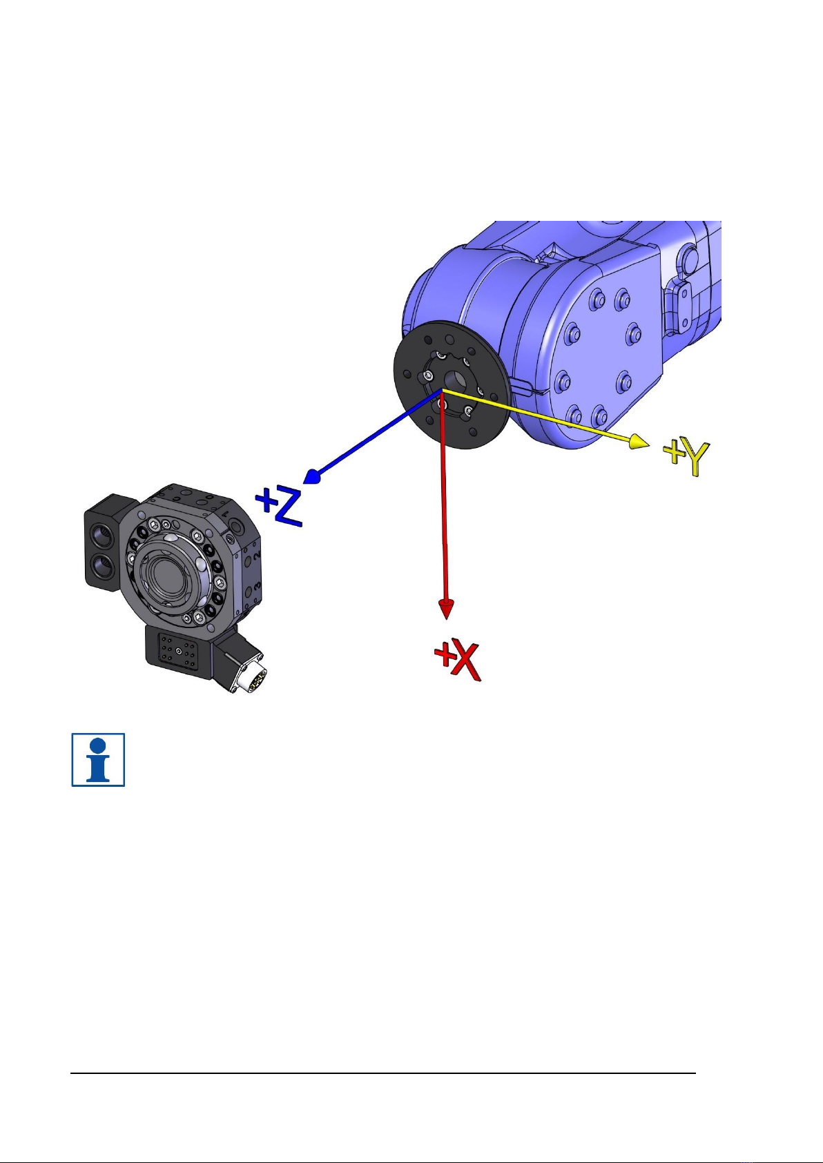
2.1.1 Coordinate System Definition...........................................................................................10
2.1.2 Tool changer TC60-8. Article no: P1301..........................................................................11
2.1.3 Tool attachment, TA60-8. Article no: P1302....................................................................12
2.1.4 Tool changer TC120-8. Article no: P1401........................................................................13
2.1.5 Tool attachment, TA120-8. Article no: P1402 ..................................................................14
2.1.6 Tool changer TC180-8. Article no: P1801........................................................................15
2.1.7 Tool attachment, TA180-8. Article no: P1802 ..................................................................16
2.1.8 Pneumatic diagram for P1301, P1401 and P1801...........................................................17
2.2 Options for tool changers and tool attachments........................................................18
2.2.1 Signal interface Souriau, robot side. Article no: P1305....................................................18
2.2.2 Signal interface Souriau, tool side. Article no: P1306 ......................................................19
2.2.3 Circuit diagram E0182-001 for P1305/P1306 ..................................................................20
2.2.4 Signal interface Souriau, robot side. Article no: P1311....................................................21
2.2.5 Signal interface Souriau, tool side. Article no: P1312 ......................................................22
2.2.6 Circuit diagram E0182-002 for P1311/P1312 ..................................................................23
2.2.7 Servo power interface Souriau, robot side. Article no: P1307 .........................................24
2.2.8 Servo power interface Souriau, tool side. Article no: P1308............................................25
2.2.9 Circuit diagram E0182-003 for P1307/P1308 ..................................................................26
2.2.10 High voltage interface, robot side. Article no: P1322.....................................................27
2.2.11 High voltage interface, tool side. Article no: P1323 .......................................................28
2.2.12 Circuit diagram E0182-026 for P1322/P1323 ................................................................29
2.2.13 Air coupling 2 channels, robot side. Article no: P1325...................................................30
2.2.14 Air coupling 2 channels, tool side. Article no: P1326.....................................................31
2.2.15 Magnetic sensors TC Opened/TC Closed. Article no: P1324........................................32
2.2.16 Guide pins. Article no: P1314.........................................................................................33
2.2.17 Parking bracket kit. Article no: P1313 ............................................................................34
2.2.18 Parking bracket kit. Article no: P1331 ............................................................................35
2.2.19 Parking bracket kit. Article no: P1405 ............................................................................36
2.2.20 Parking bracket kit. Article no: P1805 ............................................................................37
2.2.21 Tool stand kit. Article no: P0423.....................................................................................38
2.2.22 Robot Adaptation Kits.....................................................................................................39
2.3 Limitation of Robot movements................................................................................39
2.4 Connection kits and cables.......................................................................................39
3 INSTALLATION.....................................................................................................40
3.1 Tightening torques....................................................................................................40
3.2 Recommended tools for installation..........................................................................40
3.3 Installation of tool changer on robot..........................................................................41
3.4 Installation of tool attachment to the gripper/tool.......................................................43