ROBOTOUS RFT Series User manual

RFTSeries|6AxisForceTorqueSensor
©ROBOTOUSCo.,Ltd.www.robotous.com|[email protected]
1
6 Axis Force Torque Sensor
RFT Series
Installation and Operation Manual
REVISION 1.8
ROBOTOUS Co., Ltd.

RFTSeries|6AxisForceTorqueSensor
©ROBOTOUSCo.,Ltd.www.robotous.com|[email protected]
2
Contents
1. Caution ·························································································································································· 4
1.1. Notices ···································································································································································································4
1.2. Warning ·································································································································································································4
2. Installation ···················································································································································· 5
2.1. Overview ·······························································································································································································5
2.2. Power Supply Specifications ·························································································································································6
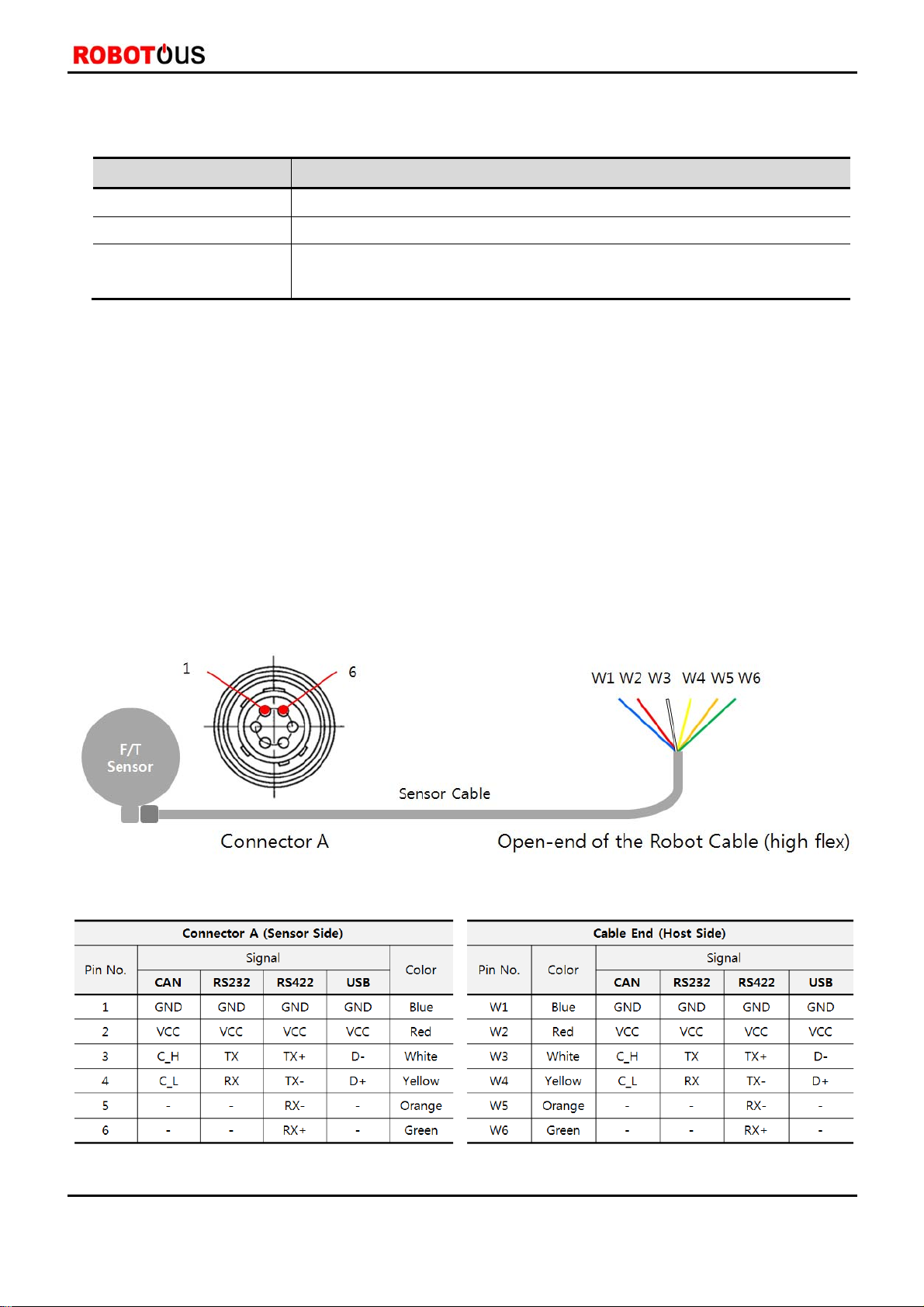
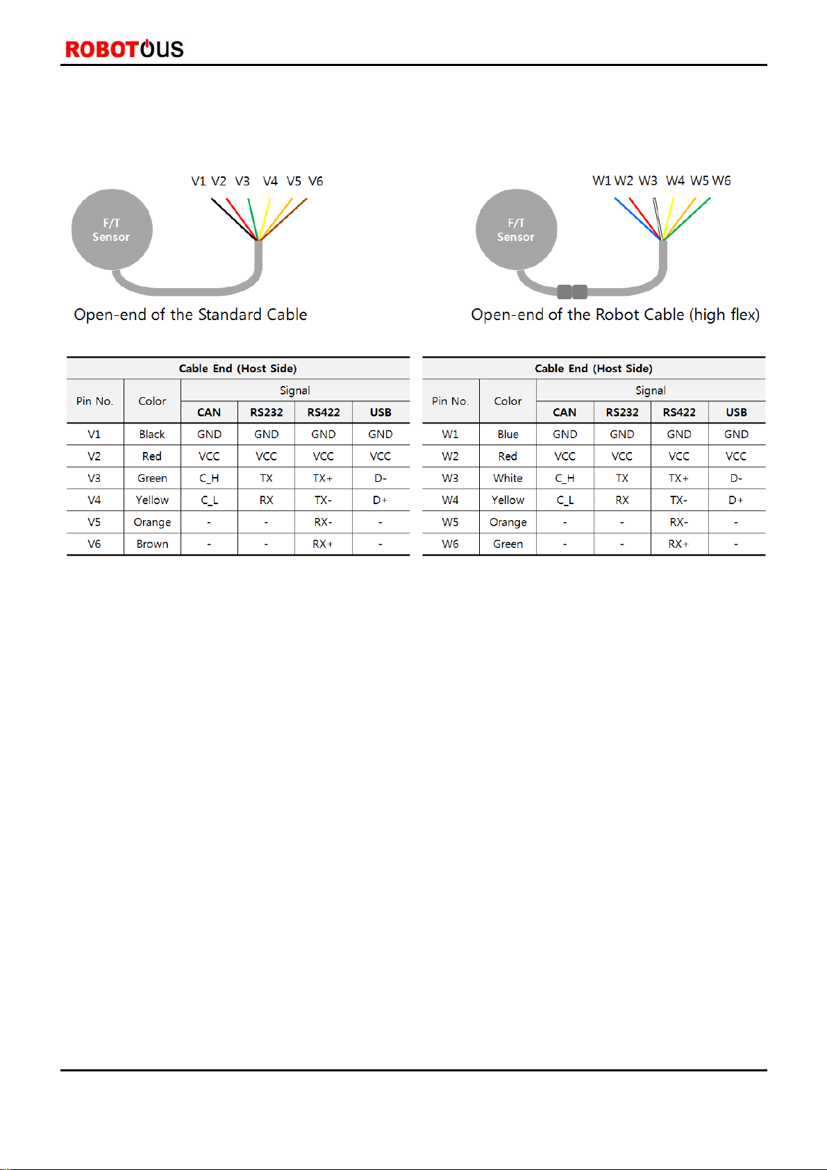
2.3. Wiring ····································································································································································································6
3. Operation ······················································································································································ 8
3.1. F/T Sensor Output Interfaces ·······················································································································································8
3.2. Communication Packets ·································································································································································8
3.3. Basic Operation ··················································································································································································8
3.4. Default Setting of Communication ············································································································································9
3.5. Packet Structure ·············································································································································································· 10
3.5.1. Packet Structure of CAN Interface ······················································································································································· 10
3.5.2. Packet Structure of UART interface······················································································································································ 10
3.6. Packet Definition ············································································································································································ 11
3.6.1. Summary of command packets ···························································································································································· 11
3.6.2. Read Model Name ······················································································································································································ 11
3.6.3. Read Serial Number ··················································································································································································· 12
3.6.4. Read Firmware Version ············································································································································································· 12
3.6.5. Set Communication ID (for CAN only) ·············································································································································· 12
3.6.6. Read Communication ID (for CAN only) ··········································································································································· 13
3.6.7. Set Baud-rate (for UART only) ······························································································································································· 13
3.6.8. Read Baud-rate ····························································································································································································· 1 4
3.6.9. Set Filter ·········································································································································································································· 14
3.6.10. Read Filter Setting ···················································································································································································· 15
3.6.11. Read F/T Data (once) ·············································································································································································· 15
3.6.12. Start F/T Data Output ············································································································································································· 17
3.6.13. Stop F/T Data Output ············································································································································································· 17
3.6.14. Set Data Output Rate ············································································································································································· 17
3.6.15. Read Data Output Rate ·········································································································································································· 18
3.6.16. Allowable Data Output Rate ································································································································································ 18
3.6.17. Set Bias ·········································································································································································································· 19

RFTSeries|6AxisForceTorqueSensor
©ROBOTOUSCo.,Ltd.www.robotous.com|[email protected]
3
3.6.18. Read Count of Overload Occurrence ··············································································································································· 19
3.6.19. Error Codes ·································································································································································································· 19
3.7. C Sample Code for Force & Torque Conversion ·············································································································· 20
3.7.1. CAN Interface ································································································································································································ 20
3.7.2. UART Interface ······························································································································································································ 21
4. Product Specification ······························································································································· 22
4.1. Performance specifications ························································································································································ 22
4.2. Data output interface ··································································································································································· 22
5. Product Ordering Information ··············································································································· 23
6. Contact Information (Technical Support) ···························································································· 24
7. APPENDIX: Dimensions of RFT Series ·································································································· 24

RFTSeries|6AxisForceTorqueSensor
©ROBOTOUSCo.,Ltd.www.robotous.com|[email protected]
4
1. Caution
1.1. Notices
The user must read and understand all of the instructions in this manual before using the RFT series F/T
sensors.
This manual covers installation, operation, specification, and ordering information of RFT series F/T
sensors..
1.2. Warning
Do not install and operate a F/T sensor that is damaged or lacking some parts.
Do not disassemble or repair the sensor for any purpose. This may cause irreparable damage to the
sensor and void the warranty.
Always take payload applied to the F/T sensor into consideration for safe usage.
Do not exert excessive forces or torques on the sensor. This can create incorrect measurement and
cause damage to the sensor. When force is applied to the sensor, torque is exerted on the sensor
simultaneously. Make sure all components of force and torque stay within allowed ranges. Even if a
component of them exceeds its limit, this may result in incorrect measurement of the other component.
Refer to Section 4.1 Performance Specifications.
If the sensor experiences a sudden change in temperature and humidity, the sensor’s temperature
correction feature may no longer function correctly and cause erratic sensor output. Please ensure the
sensor is not subject to sudden changes in temperature and humidity.
Do not remove or damage the label on sensor to maintain warranty.

RFTSeries|6AxisForceTorqueSensor
©ROBOTOUSCo.,Ltd.www.robotous.com|[email protected]
5
2. Installation
2.1. Overview
CapacitiveType
Sensingcapacitancevariationby
structuraldeformation
HighDurability
Mechanicaloverloadprotection,
noadhesive
LowCost
Simplestructure,simplified
fabricationprocess
ReliablePerformance
Immunitytoelectricalnoise,
robustcalibration,nosensordrift
EasyInstallationAll‐in‐onedevice
withembeddedsignalprocessing,
interfacesoftwaresupport
VariousOutputOptions
RS422,RS232,CAN,USB,and
EtherCAT
Item RFT90-6A01 RFT80-6A02 RFT80-6A01 RFT64-6A01
Product Image
Hollow Core ●
Dust Seal
Temp. Compensation ●●●
Item RFT64-SB01 RFT60-HA01 RFT44-SB01 RFT40-SA01
Product Image
Hollow Core ●
Dust Seal ●●
Temp. Compensation

RFTSeries|6AxisForceTorqueSensor
©ROBOTOUSCo.,Ltd.www.robotous.com|[email protected]
6
2.2. Power Supply Specifications
Item RFT Series
Input voltage 5V DC
Max. power consumption 0.5W
Warning Input voltage tolerance: ±10%
The F/T sensor may be damaged if input voltage exceeds the limits.
2.3. Wiring
General notices
Sensor output interface may have a different mapping between wire colors and functions. Please make sure
each wire color matches a correct function while connecting to a corresponding interface.
For CAN and RS-422, the user has to connect a terminal resistor of 120Ωfor normal operation, because the
sensor doesn’t have any terminal resistor inside.
The shield line is connected to the internal GND, so it doesn’t have to be connected to any ground outside.
For RS-232, the RX from one device should go to the TX of the other, and vice-versa.
RFT90-6A01 | RFT80-6A02 | RFT80-6A01

RFTSeries|6AxisForceTorqueSensor
©ROBOTOUSCo.,Ltd.www.robotous.com|[email protected]
7
RFT64-6A01 | RFT64-SB01 | RFT60-HA01 | RFT44-SB01 | RFT40-SA01

RFTSeries|6AxisForceTorqueSensor
©ROBOTOUSCo.,Ltd.www.robotous.com|[email protected]
8
3. Operation
3.1. F/T Sensor Output Interfaces
CAN (Control Area Network)
RS-232
RS-422
USB (Virtual COM port)
EtherCAT (with an external board (e.g., RFTEC-02), embedded for RFT80-6A02 and RFT64-6A01 only)
3.2. Communication Packets
Command Packet
To transmit commands to the F/T sensor.
To set parameters of the F/T sensor.
The size of the packet depends on sensor output interfaces, refer to Section 3.5 Packet Structure.
The size of data field is 8 bytes.
Response Packet
To receive responses from the F/T sensor.
To receive the result of data processing of the command packet
The size of the packet depends on data output interfaces, refer to Section 3.5 Packet Structure.
The size of data field is 16 bytes
3.3. Basic Operation
Notices
A user has to send the command “Start F/T Data Output” in order to measure and receive force and torque data
from the sensor. Otherwise, the F/T sensor stays idle even after applying power.
The F/T sensor can save current parameter settings which is valid even after rebooting it.
However, the sensor does not save the following commands: Start F/T Data Output, Stop F/T Data
Output, and Set Bias.
The following commands only are executable during measuring force and torque data: F/T Data Output Stop
and Set Bias.
The rest of commands are available in idle state or after executing the command of “Stop F/T Data
Output Stop”.
How to measure force & torque from the sensor with default setting
Step 1. Send the command “Start F/T Data Output” [Command ID = 11(0x0B)].
Step 2. Receive force and torque data from the sensor.
How to measure force & torque after setting parameters
Step 1. Send a command for parameter setting of the sensor. (Refer to Section 3.6 Packet Definition.)

RFTSeries|6AxisForceTorqueSensor
©ROBOTOUSCo.,Ltd.www.robotous.com|[email protected]
9
Step 2. Receive a corresponding response packet and check whether there was an error in processing the
command.
Step 3. Send the command “Start F/T Data Output”.
Step 4. Receive force and torque data from the sensor.
How to set a parameter while measuring force and torque.
Step 1. Send the command “Stop F/T Data Output” [Command ID = 12(0x0C)]
Step 2. Send a command for setting a parameter.
Step 3. Receive a corresponding response packet and check whether there was an error in processing the
command.
Step 4. Send the command “Start F/T Data Output”.
Step 5. Receive force and torque data from the sensor.
How to set bias while measuring force and torque
Step 1. Send the command “Start F/T Data Output” [Command ID = 11(0x0B)].
Step 2. Send the command “Set Bias” [Command ID = 17(0x11)]
Step 3. Receive force and torque data from the sensor.
3.4. Default Setting of Communication
Item
Default Values
Remarks
CAN UART
Filtering Filter OFF Filter OFF
Data Output Rate 200Hz 200Hz
Message ID
Receiver ID : 100(0x64)
Transmitter ID #1: 1(0x01)
Transmitter ID #2: 2(0x02)
N/A CAN only
Communication
Setting
CAN 2.0 A, B Compatible
Identifier: Standard Identifier
Bit Rate: 1Mbps
Size of Data: 8 Bytes
Baud Rate: 115,200bps
1 Stop Bit
No Parity
No Flow Control
Data Length: 8 Bits

RFTSeries|6AxisForceTorqueSensor
©ROBOTOUSCo.,Ltd.www.robotous.com|[email protected]
10
3.5. Packet Structure
3.5.1. Packet Structure of CAN Interface
The message structure of a standard CAN communication is shown in the figure above.
Maximum data field size of a CAN packet is 8 bytes.
The force/torque sensor uses the arbitration field (message ID) and data field of CAN packet.
The command packet needs a message ID to send 1 byte command to the sensor.
Receiver ID of CAN communication is a message ID for receiving commands.
The default receiver ID is 100 (0x64).
Refer to Section 3.6 Packet Definition for more information.
The response packet needs 2 message IDs to receive 16 bytes data from the sensor. In other words, it is made
of two sequential CAN packets.
Transmitter ID #1 and transmitter ID #2 are message IDs for the two sequential CAN packets,
respectively.
The default transmitter ID #1 is 1(0x01).
The default transmitter ID #2 is 2(0x02).
8 bytes data in a CAN packet with transmitter ID #1 occupies Data 1- Data 8 of the response packet
data field.
8 bytes data in a CAN packet with transmitter ID #2 occupies Data 9 – Data 16 of the response packet
data field.
3.5.2. Packet Structure of UART interface
Command Packet Structure
SOP Data Field Checksum EOP
Data 1 . . . Data 8
85(0x55) Command Data Field 170(0xAA)
Response Packet Structure
SOP Data Field Checksum EOP
Data 1 . . . Data 16
85(0x55) Response Data Field 170(0xAA)
RS-232, RS-422, and USB interfaces utilize UART communication.
UART packet structure consists of SOP (Start Of Packet), Data Field, Checksum and EOP (End Of Packet)
Message ID Data Field

RFTSeries|6AxisForceTorqueSensor
©ROBOTOUSCo.,Ltd.www.robotous.com|[email protected]
11
The size of SOP field is 1 byte, it is fixed to 85(0x55).
The size of EOP field is 1 byte, it is fixed to 170(0xAA).
The data field of the command packet has 8 bytes length.
The data field of the response packet has 16 bytes length.
The size of the checksum field is 1 byte, the checksum value is summation of each data in data field.
3.6. Packet Definition
3.6.1. Summary of command packets
Command Command
ID No. of
Parameters w/ Response
Packet Remarks
Read Model Name 1(0x01) 0 Yes
Read Serial Number 2(0x02) 0 Yes
Read Firmware Version 3(0x03) 0 Yes
Set Communication ID 4(0x04) 3 Yes CAN only
Read Communication ID 5(0x05) 0 Yes CAN only
Set Baud-rate 6(0x06) 1 Yes UART only
Read Baud-rate 7(0x07) 0 Yes
Set Filter 8(0x08) 2 Yes
Read Filter Setting 9(0x09) 0 Yes
Read F/T data (once) 10(0x0A) 0 Yes
Start F/T Data Output 11(0x0B) 0 Yes
Stop F/T Data Output 12(0x0C) 0 No Available even during data output
Reserved 13(0x0D) N.A. N.A.
Reserved 14(0x0E) N.A. N.A.
Set Data Output Rate 15(0x0F) 1 Yes
Read Data Output Rate 16(0x10) 0 Yes Available even during data output
Set Bias 17(0x11) 1 No
Read Count of Overload
Occurrence 18(0x12) 0 Yes
3.6.2. Read Model Name
Data field of command packet(8byte) (XX : Don't care)
Data Field
D1 D2 D3 D4 D5 D6 D7 D8
ID XX XX XX XX XX XX XX
ID : Command ID = 1(0x01)
Data field of response packet(16byte) (XX : Don't care)
Data Field
D1 D2 D3 D4 D5 D6 D7 D8 D9 D10 D11 D12 D13 D14 D15 D16
ID R1 R2 R3 R4 R5 R6 R7 R8 R9 R10 R11 R12 R13 R14 R15
ID : Response ID = 1(0x01) <same with command ID>
R1 ~ R15 : Model name in ASCII code

RFTSeries|6AxisForceTorqueSensor
©ROBOTOUSCo.,Ltd.www.robotous.com|[email protected]
12
3.6.3. Read Serial Number
Data field of command packet(8byte) (XX : Don't care)
Data Field
D1 D2 D3 D4 D5 D6 D7 D8
ID XX XX XX XX XX XX XX
ID : Command ID = 2(0x02)
Data field of response packet(16byte) (XX : Don't care)
Data Field
D1 D2 D3 D4 D5 D6 D7 D8 D9 D10 D11 D12 D13 D14 D15 D16
ID R1 R2 R3 R4 R5 R6 R7 R8 R9 R10 R11 R12 R13 R14 R15
ID : Response ID = 2(0x02) <same with command ID>
R1 ~ R15 : S/N in ASCII code
3.6.4. Read Firmware Version
Data field of command packet(8byte) (XX : Don't care)
Data Field
D1 D2 D3 D4 D5 D6 D7 D8
ID XX XX XX XX XX XX XX
ID : Command ID = 3(0x03)
Data field of response packet(16byte) (XX : Don't care)
Data Field
D1 D2 D3 D4 D5 D6 D7 D8 D9 D10 D11 D12 D13 D14 D15 D16
ID R1 R2 R3 R4 R5 R6 R7 R8 R9 R10 R11 R12 R13 R14 R15
ID : Response ID = 3(0x03) <same with command ID>
R1 ~ R15 : Firmware Version in ASCII code
3.6.5. Set Communication ID (for CAN only)
Data field of command packet(8byte) (XX : Don't care)
Data Field
D1 D2 D3 D4 D5 D6 D7 D8
ID Receiver ID Transmitter ID#1 Transmitter ID#2 XX XX XX XX
ID : Command ID = 4(0x04)
Receiver ID: ID of Force/Torque sensor
Transmitter ID #1: the first message ID for transmitting two sequential messages
Transmitter ID #2: the second message ID for transmitting two sequential messages
Allowable range of ID: 1(0x01) ~ 255(0xFF)
Note that Receiver/transmitter IDs must differ from each other.
Data field of response packet(16byte) (XX : Don't care)
Data Field

RFTSeries|6AxisForceTorqueSensor
©ROBOTOUSCo.,Ltd.www.robotous.com|[email protected]
13
D1 D2 D3 D4 D5 D6 D7 D8 D9 D10 D11 D12 D13 D14 D15 D16
ID R1 R2 XX XX XX XX XX XX XX XX XX XX XX XX XX
ID : Response ID = 4(0x04) <same with command ID>
R1 : Result of command processing [1(0x01) : success, 0(0x00) : failure]
R2 : Refer to Section 3.6.19 Error Codes
3.6.6. Read Communication ID (for CAN only)
Data field of command packet(8byte) (XX : Don't care)
Data Field
D1 D2 D3 D4 D5 D6 D7 D8
ID XX XX XX XX XX XX XX
ID : Command ID = 5(0x05)
Data field of response packet(16byte) (XX : Don't care)
Data Field
D1 D2 D3 D4 D5 D6 D7 D8 D9 D10 D11 D12 D13 D14 D15 D16
ID R1 R2 R3 R4 R5 R6 XX XX XX XX XX XX XX XX XX
ID : Response ID = 5(0x05) <same with command ID>
R1 : Current receiver ID
R2 : Current transmitter ID #1
R3 : Current transmitter ID #2
R4 : Receiver ID to set
R5 : Transmitter ID #1 to set
R6 : Transmitting ID #2 to set
Note that new receiver/transmitter IDs(R4~R6) are applied at next reboot of the sensor
3.6.7. Set Baud-rate (for UART only)
Data field of command packet(8byte) (XX : Don't care)
Data Field
D1 D2 D3 D4 D5 D6 D7 D8
ID Baud-rate parameter XX XX XX XX XX XX
ID : Command ID = 6(0x06)
Baud-rate parameter
CAN : 1Mbps, fixed
UART [Default 0(0x00): 115,200 bps]
Baud-rate
parameter Baud-rate (bps)
0(0x00) 115,200
1(0x01) 921,600
2(0x02) 460,800
3(0x03) 230,400
4(0x04) 115,200

RFTSeries|6AxisForceTorqueSensor
©ROBOTOUSCo.,Ltd.www.robotous.com|[email protected]
14
5(0x05) 57,600
Data field of response packet(16byte) (XX : Don't care)
Data Field
D1 D2 D3 D4 D5 D6 D7 D8 D9 D10 D11 D12 D13 D14 D15 D16
ID R1 R2 XX XX XX XX XX XX XX XX XX XX XX XX XX
ID : Response ID = 6(0x06) <same with command ID>
R1 : Result of command processing [1(0x01) : success, 0(0x00) : failure]
R2 : Refer to Section 3.6.19 Error Codes
Notices
- Note that baud-rate is related to available data output rates.
- Refer to Section 3.6.16 Allowable Data Output Rate
3.6.8. Read Baud-rate
Data field of command packet(8byte) (XX : Don't care)
Data Field
D1 D2 D3 D4 D5 D6 D7 D8
ID XX XX XX XX XX XX XX
ID : Command ID = 7(0x07)
Data field of response packet(16byte) (XX : Don't care)
Data Field
D1 D2 D3 D4 D5 D6 D7 D8 D9 D10 D11 D12 D13 D14 D15 D16
ID R1 R2 XX XX XX XX XX XX XX XX XX XX XX XX XX
ID : Response ID = 7(0x07) <same with command ID>
R1 : Current baud-rate
R2 : Baud-rate to set at next reboot of sensor
3.6.9. Set Filter
Data field of command packet(8byte) (XX : Don't care)
Data Field
D1 D2 D3 D4 D5 D6 D7 D8
ID Filter Type Filter
Parameter XX XX XX XX XX
ID : Command ID = 8(0x08)
Filter Type
0: No filter, 1: 1st order low-pass filter
Filter Parameter
Filter Type Filter Parameter Cutoff Frequency [Hz]
0(0x00) 0(0x00) No filter
1(0x01) 0(0x00) No filter
1(0x01) 1(0x01) 500
1(0x01) 2(0x02) 300

RFTSeries|6AxisForceTorqueSensor
©ROBOTOUSCo.,Ltd.www.robotous.com|[email protected]
15
1(0x01) 3(0x03) 200
1(0x01) 4(0x04) 150
1(0x01) 5(0x05) 100
1(0x01) 6(0x06) 50
1(0x01) 7(0x07) 40
1(0x01) 8(0x08) 30
1(0x01) 9(0x09) 20
1(0x01) 10(0x0A) 10
1(0x01) 11(0x0B) 5
1(0x01) 12(0x0C) 3
1(0x01) 13(0x0D) 2
1(0x01) 14(0x0E) 1
Data field of response packet(16byte) (XX : Don't care)
Data Field
D1 D2 D3 D4 D5 D6 D7 D8 D9 D10 D11 D12 D13 D14 D15 D16
ID R1 R2 XX XX XX XX XX XX XX XX XX XX XX XX XX
ID : Response ID = 8(0x08) <same with command ID>
R1 : Result of command processing [1(0x01) : success, 0(0x00): failure]
R2 : refer to Section 3.6.19 Error Codes
3.6.10. Read Filter Setting
Data field of command packet(8byte) (XX : Don't care)
Data Field
D1 D2 D3 D4 D5 D6 D7 D8
ID XX XX XX XX XX XX XX
ID : Command ID = 9(0x09)
Data field of response packet(16byte) (XX : Don't care)
Data Field
D1 D2 D3 D4 D5 D6 D7 D8 D9 D10 D11 D12 D13 D14 D15 D16
ID R1 R2 XX XX XX XX XX XX XX XX XX XX XX XX XX
ID : Response ID = 9(0x09) <same with command ID>
R1 : Filter type
R2 : Filter parameter
3.6.11. Read F/T Data (once)
Data field of command packet(8byte) (XX : Don't care)
Data Field
D1 D2 D3 D4 D5 D6 D7 D8
ID XX XX XX XX XX XX XX
ID : Command ID = 10(0x0A)

RFTSeries|6AxisForceTorqueSensor
©ROBOTOUSCo.,Ltd.www.robotous.com|[email protected]
16
Data field of response packet(16byte) (XX : Don't care)
Data Field
D1 D2 D3 D4 D5 D6 D7 D8 D9 D10 D11 D12 D13 D14 D15 D16
ID R1 R2 R3 R4 R5 R6 R7 R8 R9 R10 R11 R12 R13 XX XX
ID : Response ID = 10(0x0A) <same with command ID>
R1 ~ R12 : Each value of the force and torque is composed of 2byte(signed short)
R1 : Fx's upper byte, R2 : Fx's lower byte
R3 : Fy's upper byte, R4 : Fy's lower byte
R5 : Fz's upper byte, R6 : Fz's lower byte
R7 : Tx's upper byte, R8 : Tx's lower byte
R9 : Ty's upper byte, R10 : Ty's lower byte
R11 : Tz's upper byte, R12: Tz's lower byte
How to convert to force and torque values
R13 : Status of Overload
Status of Overload
Bit7 Bit6 Bit5
(Fx) Bit4
(Fy) Bit3
(Fz) Bit2
(Tx) Bit1
(Ty) Bit0
(Tz)
Reserved Reserved 0/1 0/1 0/1 0/1 0/1 0/1
If each components of force and torque exceed its rated load capacity by more than 20%, the
corresponding bit is set to 1, and reset to 0 if not.
Divider DF, DT
Divider
Model DF DT
RFT80-6A02 50 1000
RFT80-6A01 50 1000
RFT64-6A01 50 1000
RFT64-SB01 50 2000
RFT60-HA01 50 2000
RFT44-SB01 50 2000
RFT40-SA01 50 2000
Casting
Torque = raw/DT
Force = raw/DF
float 32bit
raw
signed 16bit
Upper byte
unsigned 8bit Cell = 256 x [upper byte] + [lower byte]
unsigned 16bit
float 32bit
unsigned 8bit
Lower byte

RFTSeries|6AxisForceTorqueSensor
©ROBOTOUSCo.,Ltd.www.robotous.com|[email protected]
17
3.6.12. Start F/T Data Output
Data field of command packet(8byte) (XX : Don't care)
Data Field
D1 D2 D3 D4 D5 D6 D7 D8
ID XX XX XX XX XX XX XX
ID : Command ID = 11(0x0B)
Data field of response packet(16byte) (XX : Don't care)
Data Field
D1 D2 D3 D4 D5 D6 D7 D8 D9 D10 D11 D12 D13 D14 D15 D16
ID R1 R2 R3 R4 R5 R6 R7 R8 R9 R10 R11 R12 R13 XX XX
ID : Response ID = 11(0x0B) <same with command ID>
R1 ~ R12 : Each components of force & torque are composed of 2 parameters as follows:
R1 : Fx's upper byte, R2 : Fx's lower byte
R3 : Fy's upper byte, R4 : Fy's lower byte
R5 : Fz's upper byte, R6 : Fz's lower byte
R7 : Tx's upper byte, R8 : Tx's lower byte
R9 : Ty's upper byte, R10 : Ty's lower byte
R11 : Tz's upper byte, R12: Tz's lower byte
Refer to Section 3.6.11.Read F/T Data to get real force & torque values.
R13 : Status of Overload, refer to Section 3.6.11.
3.6.13. Stop F/T Data Output
Data field of command packet(8byte) (XX : Don't care)
Data Field
D1 D2 D3 D4 D5 D6 D7 D8
ID XX XX XX XX XX XX XX
ID : Command ID = 12(0x0C)
Data field of response packet
This command is not followed by any response packet.
3.6.14. Set Data Output Rate
Data field of command packet(8byte) (XX : Don't care)
Data Field
D1 D2 D3 D4 D5 D6 D7 D8
ID Output Rate Parameter XX XX XX XX XX XX
ID : Command ID = 15(0x0F)
Output Rate Parameter
Default : 0 [200Hz]
Refer to Section 3.6.16 Allowable Data Output Rate
Data field of response packet(16byte) (XX : Don't care)
Data Field
D1 D2 D3 D4 D5 D6 D7 D8 D9 D10 D11 D12 D13 D14 D15 D16

RFTSeries|6AxisForceTorqueSensor
©ROBOTOUSCo.,Ltd.www.robotous.com|[email protected]
18
ID R1 R2 XX XX XX XX XX XX XX XX XX XX XX XX XX
ID : Response ID = 15(0x0F) <same with command ID>
R1 : Result of command processing [1(0x01): success, 0(0x00): failure]
R2 : Refer to Section 3.6.19 Error Code for error code
Notice:
- High data output rate may not work at a low baud-rate.
- Please refer to Section 3.6.16 Allowable Data Output Rate
3.6.15. Read Data Output Rate
Data field of command packet(8byte) (XX : Don't care)
Data Field
D1 D2 D3 D4 D5 D6 D7 D8
ID XX XX XX XX XX XX XX
ID : Command ID = 16(0x10)
Data field of response packet(16byte) (XX : Don't care)
Data Field
D1 D2 D3 D4 D5 D6 D7 D8 D9 D10 D11 D12 D13 D14 D15 D16
ID R1 XX XX XX XX XX XX XX XX XX XX XX XX XX XX
ID : Response ID = 16(0x10) <same with command ID>
R1 : Refer to Section 3.6.16 Allowable Data Output Rate
3.6.16. Allowable Data Output Rate
CAN Interface
Communication Output Rate Parameter (Output rate, Hz)
Baud-rate Parameter 0x00
(200)
0x01
(10)
0x02
(20)
0x03
(50)
0x04
(100)
0x05
(200)
0x06
(333)
0x07
(500)
0x08
(1000)
XX 1Mbps O O O O O O O O O
Default Baud-rate: 1Mbps Fixed
Default Output-rate: 0 [200Hz]
UART Interface
Communication Output Rate Parameter (Output rate, Hz)
Baud-rate Parameter 0
(200) 1
(10) 2
(20) 3
(50) 4
(100) 5
(200) 6
(333) 7
(500) 8
(1000)
0 115,200bps O O O O O O O X X
1 921,600bps O O O O O O O O O
2 460,800bps O O O O O O O O X
3 230,400bps O O O O O O O O X
4 115,200bps O O O O O O O X X
5 57,600bps O O O O O O X X X

RFTSeries|6AxisForceTorqueSensor
©ROBOTOUSCo.,Ltd.www.robotous.com|[email protected]
19
Default Baud-rate: 115,200bps
Default Output-rate: 0 [200Hz]
3.6.17. Set Bias
Receiving the command with set-bias, the sensor saves current output values as a reference and begins to
send offset of the following output values from the reference.
Receiving the command with un-bias, the sensor begins to send offset of the following output values from the
factory bias which is a reference saved in a factory setting.
Data field of command packet(8byte) (XX : Don't care)
Data Field
D1 D2 D3 D4 D5 D6 D7 D8
ID Bias parameter XX XX XX XX XX XX
ID : Command ID = 17(0x11)
Bias parameter 0(0x00): un-bias,
Bias parameter 1(0x01): set-bias
Data field of response packet
This command is not followed by any response packet.
3.6.18. Read Count of Overload Occurrence
Data field of command packet(8byte) (XX : Don't care)
Data Field
D1 D2 D3 D4 D5 D6 D7 D8
ID XX XX XX XX XX XX XX
ID : Command ID = 18(0x12)
Data field of response packet(16byte) (XX : Don't care)
Data Field
D1 D2 D3 D4 D5 D6 D7 D8 D9 D10 D11 D12 D13 D14 D15 D16
ID R1 R2 R3 R4 R5 R6 XX XX XX XX XX XX XX XX XX
ID : Response ID = 18(0x12) <same with command ID>
R1 : Number of overload occurrence of Fx
R2 : Number of overload occurrence of Fy
R3 : Number of overload occurrence of Fz
R4 : Number of overload occurrence of Tx
R5 : Number of overload occurrence of Ty
R6 : Number of overload occurrence of Tz
Maximum count of overload occurrence: 255 (0xFF)
3.6.19. Error Codes
Error Code Description
1(0x01) Unsupported command
2(0x02) Out of range error, a parameter such as ID, baud-rate, filter setting, (etc.) is out of
the allowable range.

RFTSeries|6AxisForceTorqueSensor
©ROBOTOUSCo.,Ltd.www.robotous.com|[email protected]
20
3(0x03) Failed to set parameters
3.7. C Sample Code for Force & Torque Conversion
3.7.1. CAN Interface
unsigned char data_field[16]; // storage buffer for data field
//..... Received CAN data Save .....
// 8 byte data of can message id is #1 save in data_field [0] ~ [7]
// 8 byte data of can message id is #2 save in data_field [8] ~ [15]
// data field processing
short raw_data[6] = { 0 };
unsigned short temp;
unsigned DF=50, DT=2000; // DF, DT depend on the model, refer to 3.6.11
// response ID checking
if( (data_field[0] != 10) || (data_field[0] != 11) )
return;
for (int idx = 0; idx < 6; idx++)
{
temp = data_field [2 * idx + 1] * 256;
temp += data_field [2 * idx + 2];
raw_data[idx]=(signed short)temp; // variable casting
}
// Conversion from signed short data to float data and data scaling
// Set Force/Torque Original
float ft_array[6];
for (n = 0; n < 3; n++)
{
ft_array[n] = (((float)raw_data[n] ) / DF); // refer to 3.6.11
ft_array[n + 3] = (((float)raw_data[n + 3] ) / DT); // refer to 3.6.11
}
// Overload status value
unsigned char overload_status = can_msg_data[13];
This manual suits for next models
8
Table of contents
Popular Accessories manuals by other brands

Manitowoc
Manitowoc K00344 installation instructions

Becker
Becker SensorControI SC861A Assembly and operating instructions

Honeywell
Honeywell WSK-24 installation instructions

Sunbeam
Sunbeam Carveasy Master Series user guide

Panasonic
Panasonic MA2J729 (MA729) Specification sheet

PCB Piezotronics
PCB Piezotronics 261B02 manual

NeuLog
NeuLog NUL-229 Guide

Campbell
Campbell SDM-CVO4 instruction manual

PCB Piezotronics
PCB Piezotronics PCB-(M)352C66 Installation and operating manual

Hytronik
Hytronik HMW15 Installation and instruction manual

Safeguard Supply
Safeguard Supply LRA-D1000 quick start guide

Pipistrel
Pipistrel Sinus Build manual