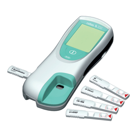
Roche Reflotron Plus User manual

Components of the
Reflotron Plus System
Introduction
The Reflotron Plus is an in vitro diagnostic device designed for the
quantitative determination of clinical chemistry parameters using
Reflotron test strips. It works on the principle of reflectance photo-
metry and ensures rapid and reliable results while being simple to
use.
Various additional components are also available for the
Reflotron Plus. These are items which are necessary or useful for per-
forming an analysis or which allow you to check the performance of
the system.
The Reflotron tests are test strips designed for the specific determin-
ation of important clinical chemistry parameters using undiluted
specimen material. The incorporation of a plasma-separating system
makes it possible to use whole blood as well as serum and plasma.
Some tests can also be performed with prediluted urine. The
Reflotron tests have a long shelf-life and, with only few exceptions,
can be stored at room temperature.
On the back of each Reflotron test strip there is a magnetic strip con-
taining all test- and lot-specific data.
Control materials for checking the performance of the Reflotron
system.
Useful additional items for use with the Reflotron Plus.
Used for cleaning and checking the optical system.
Reflotron Plus
Reflotron Tests
Reflotron Precinorm U
Reflotron Precinorm HDL
Reflotron Precinorm HB
Reflotron Accessories
Reflotron Clean and Check


Contents
Page
1. Unpacking and Installation
Checking for damage sustained during transport 1.1
Checking that the consignment is complete 1.1
Proper siting 1.2
Connection to the mains 1.3
Operation with 12/24 V DC voltage 1.4
Reflotron Workstation 1.5
Integrated printer 1.6
Connection to a computer system 1.7
Keyboard 1.7
2. Start-up and Practice
Switching on the Reflotron Plus 2.1
Standby function 2.6
Practice with Reflotron Check 2.7
Working with Reflotron tests and blood, serum or plasma 2.12
Notes on result displays in special cases 2.21
Working with capillary blood 2.24
Collection of blood using capillary blood collection tubes 2.25
Pipetting with the Reflotron Pipette 2.25
Collection of capillary blood using capillary pipettes 2.26
Obtaining capillary plasma 2.28
Storage and retrieval of results 2.29
Individual settings 2.31
– Date and time 2.32
– Setting the printer 2.34
– Acoustic signal 2.35
– Units and enzyme reference temperature 2.36
– Strip counter 2.38
– Deleting the results from memory 2.39
3. Working with Reflotron Keyboard
General instructions 3.1
Entering a patient/sample identification 3.4
Calculation of cardiac risk 3.5
– Calculation of cardiac risk according to “PROCAM” 3.5
– Calculation of cardiac risk according to “FRAMlNGHAM” 3.8
Calculation of LDL according to Friedewald 3.10
Calculation of the cholesterol/HDL cholesterol ratio 3.12
Entry of additional test information 3.14
Calculation of the creatinine clearance 3.15

Page
Labeling measurements performed with control material 3.18
Transfer of patient profiles to a computer system 3.19
– Profile transfer 3.19
– Profile transfer II 3.20
Printout of patient profiles 3.22
Printing out displayed text 3.23
4. Cleaning and Quality Checking
Cleaning the instrument 4.1
Checking the optical system with Reflotron Check 4.4
Checking the whole system with control sera 4.5
5. Display Messages and What They Mean
Routine messages 5.1
Operator messages 5.3
Error messages 5.4
6. Technical Information and Notes
Measuring principle 6.1
Software 6.3
Basic instrument settings 6.3
Printer operation 6.9
– Insertion of paper 6.9
– Changing the printer ribbon 6.9
Operation with RS 232 C interface 6.10
Temporary or permanent disuse 6.14
Technical data and specifications 6.15
Safety warning 6.18
Guarantee 6.19
General note 6.19
7. Index
8. Reflotron Tests

1. Unpacking and Installation
2. Start-up and Practice
3. Working with Reflotron Keyboard
4. Cleaning and Quality Checking
5. Display Messages and What They Mean
6. Technical Information and Notes
7. Index
8. Reflotron Tests


Unpacking
and Installation
1. Unpacking and Installation

1.1
1. Unpacking and Installation
Checking for damage sustained during transport
Reflotron Plus is delivered in two separate boxes. If the contents have
suffered any damage in transport, please inform your supplier or the
carrier at once.
Checking that the consignment is complete
The main box contains the Reflotron Plus reflectance photometer, a
Reflotron Workstation A new, a printer ribbon and printer paper.
The following items are also supplied:
1 connecting cable
1 instruction manual
and other items such as the following, if ordered:
1 Reflotron Pipette
1 applicator incl. 50 capillary pipettes
1 Accu-Chek Softclix Pro incl. Accu-Chek Softclix Pro Lancets
1 Reflotron Clean and Check
If any items are missing, please inform your supplier at once.

1.2
Proper siting
Do not expose Reflotron Plus to direct sunlight.
Do not put the instrument near sources of heat, such as radiators,
heaters or instruments radiating heat.
To ensure trouble-free performance, keep the Reflotron Plus in a
room with a temperature between +15°C and +34°C and a relative
humidity of not more than 95%.
Operate the Reflotron Plus at a distance of at least 4 m from
diathermy units as these can interfere with the functioning of elec-
tronic instruments.

1.3
Connection to the mains
Reflotron Plus covers a voltage range of 115 V to 230 V (+/–22 %).
Before plugging in Reflotron Plus, please check that your mains
voltage lies within the range covered by the instrument.
If it does not, please contact your supplier.
As soon as the mains cable is plugged in, Reflotron Plus is ready for
use.
Checking the mains voltage
Connecting the mains cable

Operation with 12/24 V DC voltage
Reflotron Plus can be adapted for additional operation with 12/24 V
DC voltage so that the instrument can be operated with a car battery,
for example.
Please contact your supplier or Roche Diagnostics for further infor-
mation on this option.
When operating a Reflotron Plus adapted for use with direct current
attention should be paid to the following points:
Voltage fluctuations are permissible in the 10–30 V range.
Connect the battery to the DC socket, making sure that polarity is
correct. Reflotron Plus does not function with false polarity. It is, how-
ever, provided with reverse battery protection.
While operating Reflotron Plus with direct current it must be
disconnected from the mains.
A connecting cable (1.5 m) with the recommended Cannon
AXR-3-11 plug can also be ordered from Roche Diagnostics under
REF 1 1331582.
If you want to connect Reflotron Plus to the electrical system of your
car, please consult a car electrician.
Do not start the engine while performing a measurement.
For further technical details, R see Section 6. “Technical Information
and Notes”.
1.4
Leads of the socket
1 2
3
+ –

1.5
Reflotron Workstation
Reflotron Workstation accommodates all other materials needed for
the analysis so that they are always close to hand.
Reflotron Plus is supplied together with the Workstation A new
(without contents) shown on the left.
The Reflotron Workstation A new (without contents) can also be
ordered under REF 1 1902091.
The following Reflotron Workstations can also be ordered from Roche
Diagnostics as accessories. (The pictures illustrate how the worksta-
tions can be filled. All workstations are supplied without contents.)
Workstation B REF 1 1248944
Workstation C REF 1 1248952

1.6
Integrated printer
Reflotron Plus is fitted with an integrated printer.
If the first printout is blank or too faint, the “paper feed” button must
be depressed for some time.
The procedure for changing the printer ribbon and inserting a new roll
of paper is described in Section 6.
The printer ribbon (Epson ERC 09, black) is available from Roche
Diagnostics under REF 1 0745235.
The paper (width 58 mm, diameter of roll 60 mm) is supplied by
Roche diagnostics under REF 1 1268457.

1.7
Connection to a computer system
The serial interface allows the Reflotron Plus to be connected to a
practice or laboratory computer system.
For further details see Section 6 “Operation with RS 232 C interface”.
Keyboard
Reflotron Plus has additional functions which can only be used in
combination with a keyboard. A conventional IBM compatible key-
board may be used. In this case the legal regulations for emission of
interfering radiation must be observed.
The Reflotron Keyboard supplied by Roche Diagnostics is available in
various versions for different countries.
The keyboard is connected to the keyboard socket on the rear of the
instrument with the Reflotron Plus switched off.
Connecting the keyboard


Start-up
and Practice
2. Start-up and Practice

2.1
2. Start-up and Practice
Switching on the Reflotron Plus
Plugging in the mains cable
When the mains cable has
been plugged in or an appropri-
ately adapted Reflotron Plus
has been connected to a suit-
able DC source, the instrument
is ready for operation.
Attention!
Never obstruct the vents on the
top of the apparatus or the fan
outlet at the bottom.
The prerequisites described
under “Proper siting” (R see
Section 1) must be satisfied.

2.2
Preliminary remarks
The meanings of the various
display messages are explained
below. Display messages
indicating
appear on a neutral back-
ground, messages indicating
appear on a light grey back-
ground.
Display messages on a dark
grey background indicate either
For a detailed description
of display messages, see
Section 5 “Display Messages
and What They Mean”.
correct operation
differing procedure
incorrect operation
or instrument faults

2.3
Switching on the instrument
After switching on the
Reflotron Plus using the on/off
switch, all segments of the dis-
play appear for about 2 sec-
onds. Check that the display
appears exactly as shown on
the left. The lines under the
segments should be flashing.
If any dots or segments are
missing the result shown may
be incorrect. In this case please
contact your supplier.
Next the date, the time (shown
here) and MXX.XX CXX.XX will
appear. MXX.XX CXX.XX is
coded information for the cus-
tomer service staff, e.g. M06.17
C06.02.
If the instrument does not dis-
play the correct date and/or
time, they can be adjusted. See
“Individual settings” in Section 2
for appropriate instructions.
The next step is warming up,
the duration of which depends
on the inside temperature of the
apparatus.
The time remaining until the
system is ready for analysis is
displayed at intervals of 1 sec.
_
❚_
❚_
❚_
❚_
❚_
❚_
❚_
❚_
❚_
❚_
❚_
❚_
❚_
❚_
❚_
❚_
❚_
❚_
❚_
❚_
❚_
❚_
❚_
❚
_
❚_
❚_
❚_
❚_
❚_
❚_
❚_
❚_
❚_
❚_
❚_
❚_
❚_
❚_
❚_
❚_
❚_
❚_
❚_
❚_
❚_
❚_
❚_
❚
15.05.01 09:32:33
WARMING UP 180 sec
15.05.01 09:35:33
READY
15.05.01 09:32:30
MXX.XX CXX.XX

2.4
If the messages appear in the
wrong language, e.g.
or the time is not displayed in
the desired format, e.g.
please see “Basic instrument
settings” in Section 6 for infor-
mation on how to make the
necessary adjustments.
Our customer service staff will
be glad to help you change the
settings.
15.05.01 09:35:33
REFLOTRON PRONTO
05.15.01 PM 09:32:30
MXX.XX CXX.XX
Table of contents
Other Roche Laboratory Equipment manuals
Popular Laboratory Equipment manuals by other brands

NUVE
NUVE BM 15 instruction manual

Medisafe
Medisafe SI PCF user manual

Thermo Scientific
Thermo Scientific Fisher Scientific Fisherbrand GT1R... instruction manual

VERDER
VERDER Carbolite Gero HTMA 6/95 Installation, operation and maintenance instructions

Parker
Parker PICOSPRITZER III manual

WPI
WPI LWCC-M-10 instruction manual

Munchkin
Munchkin 59S owner's manual

Agilent Technologies
Agilent Technologies EXSLRSH110 instruction manual

Agilent Technologies
Agilent Technologies 7697A Installation and startup guide

Plasmapp
Plasmapp STERLINK U-510 user manual

Puls
Puls POE.8AT-DC1 installation manual

V&P Scientific
V&P Scientific 418SV2-2x4-50CB-CC operating instructions