Essilor AKR 550 User manual

Auto kerato refractometer
Maintenance Manual
V1 –09/2016

1
Contents
1External View................................................................................................................. 2
2Internal Structural Diagram ........................................................................................ 3
3Measurement Principle ................................................................................................. 4
4Block Diagram................................................................................................................ 5
5Connection Diagram ...................................................................................................... 6
6Wiring Diagram ............................................................................................................. 8
7Troubleshooting............................................................................................................ 11
8Cleaning of Eye Lens, Measurement Window Filter and Model Eye ASSY ........... 33
9Functional Check ......................................................................................................... 34
10 Maintenance Mode ...................................................................................................... 35
11 Evaluation of Freeze Image........................................................................................ 46
12 Replacement Procedure of Each Unit........................................................................ 48
13 Rewriting procedures of the software of AKR550..................................................... 56
14 Packing mode............................................................................................................... 60

2
1External View
No.
Name
No.
Name
1
LCD monitor
12
Power plug connector
2
Touch-sensitive panel
13
Rating plate
3
Printer cover
14
Chinrest
4
Base
15
Body cover
5
Rubber leg
16
Face panel
6
Main unit slide lock knob
17
Headrest
7
Measurement start switch
18
Head cover
8
Joystick
19
Printer cover button
9
Slide base cover
20
Headrest rubber
10
Power switch
21
Chinrest knob
11
External interface connector

3
2Internal Structural Diagram
No.
Name
No.
Name
1
Optical unit
12
Joystick
2
Control board
13
Slide base cover
3
Optical cover
14
Base
4
LCD monitor
15
PD meter
5
Touch sensor board
16
Vertical unit
6
LCD relay board
17
XZ unit
7
Printer
18
Power unit
8
Printer control board
19
Bottom plate
9
Measurement window ring
20
Rubber leg
10
Main unit BKT
21
Chinrest
11
Toothed belt
22
Headrest

4
3Measurement Principle
1) Measurement of eye refraction
A measurement pattern for measurement of eye refraction is projected to an eyeground to
be measured.
The projected pattern changes its size depending on the eye’s refractive power. The reflect
light of this eyeground image is led to the sensor through the measurement system. The
detected data is stored in the frame memory and conducted pattern analysis by image
processing to calculate values of S, C and A.
Rough refractive power (temporary measurement) is calculated by the first measurement
and auto fogging operation and focusing operation of eyeground images are started based
on the data. Then, the actual measurement is started and the refractive power of the eye
to be measured is calculated and displayed.
2) Measurement of corneal curvature radius
A ring-shaped measurement pattern is projected onto a cornea of an eye to be measured.
The pattern projected on the cornea varies its size depending on the corneal curvature
radius. The projected light is led to the sensor through the cornea measurement system.
The detected data is stored in the frame memory and conducted pattern analysis by
image processing to calculate values of R1, R2 and A.
Subject’s eye
Cornea
Projected light
Corneal curvature
radius: small
Corneal curvature
radius: large
Projected patterns on the sensor
Subject’s eye
Eyeground
Cornea
Projected light
Myopia
Hyperopia
Projected pattern on the sensor

5
4Block Diagram
LCD
Motor
Motor
Operation Switch
RS-232C
Interface
Focus Motor
Position Sensor
Target Motor
Position Sensor
Potentiometer
Measurement Start Switch
Main Control
Circuit Unit
EEPROM
Printer
Printer Control Circuit Unit
CMOS Camera
CMOS Camera
Ranging Sensor
Kerato LED
Target LED
Ref LED
Ranging LED
Fuse
Power Switch
Power
Inlet
Switching Supply
Basic Insulation
Reinforced Insulation
Between Primary and
Secondary
Metallic Portion with Protective Earth (Chassis)
Reinforced Insulation
LCD Relay
Circuit Unit
Headrest
Chinrest
DC 12V (SELV)
DC 5V (SELV)
AC100-240V
50/ 60Hz

6
5Connection Diagram

7

8
6Wiring Diagram
6-1 Front View
6-2 Side View
Printer Control Board
Power Switch
Optical Unit ASSY
Printer
Joystick

9
6-3 Rear View
6-4 Bottom View
PD ASSY
Switching Power Supply
SWPS Output Harness
SWPS Input Harness
Peripheral Relay Harness
Measurement Window Ring
Face Cover

10
6-5 Plane View
6-6 Back Side of LCD
LCD Relay Board
Operation
Switch Board
LCD Backlight Harness
LCD Signal Harness
Operation Switch Harness
Main Control Board
LCD Relay Harness

11
7Troubleshooting
7-1 General description of boards
7-2 Error message ‘RETRY’appears
7-3 Error message ‘EEPROM fault’appears
7-4 Error message ‘Target (Focus) Motor fault’appears
7-5 Error message ‘Printer Overheated’appears
7-6 Error message ‘Printer cover opened’appears
7-7 Error message ‘Paper empty’appears
7-8 Error message ‘Sub system time out’appears
7-9 Error message ‘Sub system data err’appears
7-10 Nothing is displayed when turning on
7-11 No responses when pressing measurement start switch
7-12 No responses when pressing operation switches
7-13 Measurement result is not printed out/ printout is not normal
7-14 Ref measurement LED does not light up
7-15 Cannot see target
7-16 Infrared illumination LED does not light up
7-17 Light source for Kerato/ illumination does not light up
7-18 Cannot communicate with PC or phoropter
7-19 Cannot measure PD (cannot measure PD correctly)
7-20 No power outlet
7-21 Abnormal measurement value of model eye ASSY

12
7-1 General description of boards
This product is composed mainly with the peripheral boards such as the boards and the various
types of sensors etc. as shown below.
Main functions of each board are described below.
1
Control board
: Control of CMOS camera, control of LCD, control of Motor,
Control of LED, control of each sensor, control of external
communication, image processing, calculation of
measurement value
2
Operation switch board
: Detection and control of switch operation
3
Printer control board
: Printing, control of paper feeding
4
LCD relay board
: Power generation for LCD and operation switch board
5
CMOS camera board
: Taking images
6
EEPROM board
: Retention of optical setting information and system setting
information
7
Motor sensor board
: Detection of limit position of each motor
8
Ranging LED board
: Light source for ranging
9
Ranging sensor board
: Sensor for ranging
10
Ref LED board
: Light source for ref
11
Target LED board
: Light source for target
12
Kerato/ Illumination board
: Light source for Kerato and illumination
13
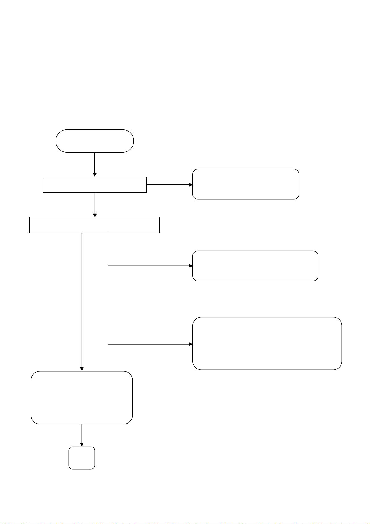
7-2 Error message ‘RETRY’appears
Main causes when error message ‘RETRY’appears:
・When the image is not caught accurately because of examinee’s condition (blinking or not
looking at target etc.)
・Alignment is not achieved correctly
・Failure of control board
・Failure of optical unit
Can a model eye be measured?
NO
YES
Check the condition of subject’s eye.
Evaluate the Freeze Image.
【Refer to 11】
‘RETRY’is displayed.
Realign correctly and take
measurements again.
【Refer to ‘6.2 Alignment’ of
operation manual】
Measurement cannot be taken in
case of disorder such as cataracts etc.
If the pupil is smaller than reticle mark,
measurements might not be taken.
Darken the surround and try to take
measurements again.
Abnormal case ②
Abnormal case ①
Normal
OK

14
7-3 Error message ‘EEPROM fault’appears
Main causes when error message ‘EEPROM fault’ appears:
・Disconnection of harnesses
・Failure of control board
・Failure of EEPROM board
YES
‘EEPROM fault’is displayed.
OK
Replace the EEPROM board.
Is ‘EEPROM fault’still displayed?
Is ‘EEPROM fault’still displayed?
Replace the control board.
Is conduction of EEPROM harness normal?
YES
YES
Perform ‘Reset of setting’
of the maintenance mode.
Replace the EEPROM harness.
NO
NO
NO

15
7-4 Error message ‘Target (Focus) Motor fault’appears.
Main causes when error message ‘Target (Focus) Motor fault’appears:
・Failure of control board
・Failure of optical unit
Is ‘Focus (Target) Motor
fault’still displayed?
‘Target (Focus) Motor fault’ is displayed.
OK
Replace the optical unit ASSY.
Replace the control board.
Replace the optical unit
ASSY and control board.
Replace the harness connected to CN703
with the one connected to CN704.
Are both ‘Target Motor fault’and
‘Focus Motor fault’displayed?
YES
YES
NO
NO

16
7-5 Error message ‘Printer Overheated’appears
Main causes when error message ‘Printer Overheated’appears:
・Printer head is hot
・Failure of printer unit
・Failure of printer control board
‘Printer Overheated’is displayed.
Replace the thermal printer.
Replace the printer control board.
OK
Is ‘Printer Overheated’still displayed?
NO
YES
Wait until the printer head is cooled down.
Is ‘Printer Overheated’still displayed?
YES
NO

17
7-6 Error message ‘Printer cover opened’appears
Main causes when error message ‘Printer cover opened’appears:
・Printer cover is opened.
・Failure of printer unit
・Failure of printer control board
Is the printer cover set correctly?
NO
YES
Set the cover correctly.
‘Printer cover opened’is displayed.
Is ‘Printer cover opened’still displayed?
Replace the printer control board.
OK
YES
NO
Replace the thermal printer.

18
7-7 Error message ‘Paper empty’appears
Main causes when error message ‘Paper empty’appears:
・No printer papers in printer
・Failure of printer unit
・Failure of printer control board
‘Paper empty’is displayed.
Is ‘Paper empty’still displayed?
Are printer papers set properly?
YES
NO
Is dust or dirt attached on the
sensor unit of printer?
NO
YES
Remove the dust or dirt.
Are there any papers in the printer?
Set the papers.
Set the printer papers properly.
Replace the printer control board.
NO
NO
YES
OK
YES
Replace the thermal printer.

19
7-8 Error message ‘Sub system time out’appears.
Main causes when error message ‘Sub system time out’appears:
・Disconnection of printer harness
・Failure of printer control board
・Failure of control board
OK
Replace the control board.
‘Sub system time out’is displayed.
Is conduction of the
printer harness normal?
Replace the printer harness.
Replace the printer control board.
NO
YES
NO
YES
Is ‘Sub system time out’still displayed?
Other manuals for AKR 550
1
Table of contents
Other Essilor Laboratory Equipment manuals


Popular Laboratory Equipment manuals by other brands


LW Scientific
LW Scientific ZIPspin instruction manual

Hanna Instruments
Hanna Instruments HI 180 instruction manual

Thermo Scientific
Thermo Scientific Nunc Cell Factory CF1 Instructions for use

MIHM-VOGT
MIHM-VOGT KM Working instructions

Integra
Integra PIPETBOY pro operating instructions

Delsys
Delsys NeuroMap quick start guide