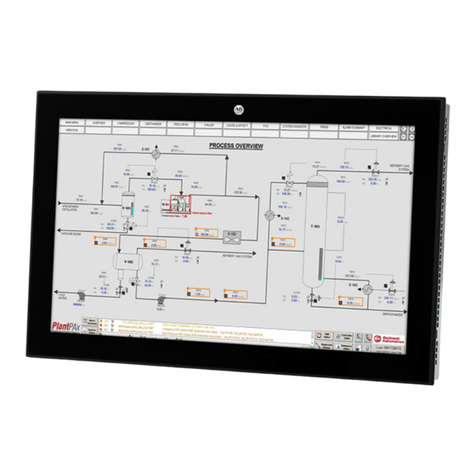
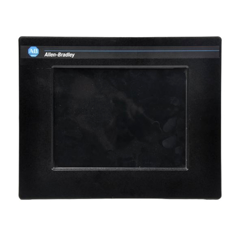
Rockwell Automation Allen-Bradley 6186M Series User manual

User Manual Original Instructions
6186M Industrial Performance
Monitors
Catalog Numbers 6186M-12PN, 6186M-12PT, 6186M-15PN,
6186M-15PT, 6186M-15PNSS, 6186M-15PTSS, 6186M-17PN,
6186M-17PT, 6186M-17PNSS, 6186M-17PTSS, 6186M-19PN,
6186M-19PT, 6186M-19PNSS, 6186M-19PTSS

2Rockwell Automation Publication 6186M-UM002C-EN-P - December 2023
6186M Industrial Performance Monitors User Manual
Important User Information
Read this document and the documents listed in the additional resources section about installation, configuration, and operation of this equipment before
you install, configure, operate, or maintain this product. Users are required to familiarize themselves with installation and wiring instructions in addition to
requirements of all applicable codes, laws, and standards.
Activities including installation, adjustments, putting into service, use, assembly, disassembly, and maintenance are required to be carried out by suitably
trained personnel in accordance with applicable code of practice.
If this equipment is used in a manner not specified by the manufacturer, the protection provided by the equipment may be impaired.
In no event will Rockwell Automation, Inc. be responsible or liable for indirect or consequential damages resulting from the use or application of this
equipment.
The examples and diagrams in this manual are included solely for illustrative purposes. Because of the many variables and requirements associated with
any particular installation, Rockwell Automation, Inc. cannot assume responsibility or liability for actual use based on the examples and diagrams.
No patent liability is assumed by Rockwell Automation, Inc. with respect to use of information, circuits, equipment, or software described in this manual.
Reproduction of the contents of this manual, in whole or in part, without written permission of Rockwell Automation, Inc., is prohibited.
Throughout this manual, when necessary, we use notes to make you aware of safety considerations.
These labels may also be on or inside the equipment to provide specific precautions.
The following icon may appear in the text of this document.
WARNING: Identifies information about practices or circumstances that can cause an explosion in a hazardous environment,
which may lead to personal injury or death, property damage, or economic loss.
ATTENTION: Identifies information about practices or circumstances that can lead to personal injury or death, property
damage, or economic loss. Attentions help you identify a hazard, avoid a hazard, and recognize the consequence.
IMPORTANT Identifies information that is critical for successful application and understanding of the product.
SHOCK HAZARD: Labels may be on or inside the equipment, for example, a drive or motor, to alert people that dangerous
voltage may be present.
BURN HAZARD: Labels may be on or inside the equipment, for example, a drive or motor, to alert people that surfaces may
reach dangerous temperatures.
ARC FLASH HAZARD: Labels may be on or inside the equipment, for example, a motor control center, to alert people to
potential Arc Flash. Arc Flash will cause severe injury or death. Wear proper Personal Protective Equipment (PPE). Follow ALL
Regulatory requirements for safe work practices and for Personal Protective Equipment (PPE).
Identifies information that is useful and can help to make a process easier to do or easier to understand.

Rockwell Automation Publication 6186M-UM002C-EN-P - December 2023 1
Table of Contents
Preface
About This Publication . . . . . . . . . . . . . . . . . . . . . . . . . . . . . . . . . . . . . . . . . . . . . . . . . . . . . . 3
Download Firmware, AOP, EDS, and Other Files 0151 . . . . . . . . . . . . . . . . . . . . . . . . . . . . . 3
Summary of Changes. . . . . . . . . . . . . . . . . . . . . . . . . . . . . . . . . . . . . . . . . . . . . . . . . . . . . . . 3
Additional Resources . . . . . . . . . . . . . . . . . . . . . . . . . . . . . . . . . . . . . . . . . . . . . . . . . . . . . . . 3
Chapter 1
Overview Features. . . . . . . . . . . . . . . . . . . . . . . . . . . . . . . . . . . . . . . . . . . . . . . . . . . . . . . . . . . . . . . . . . 5
Product Catalog Numbers . . . . . . . . . . . . . . . . . . . . . . . . . . . . . . . . . . . . . . . . . . . . . . . . . . . 5
Peripheral Connections . . . . . . . . . . . . . . . . . . . . . . . . . . . . . . . . . . . . . . . . . . . . . . . . . . . . . 6
Accessories . . . . . . . . . . . . . . . . . . . . . . . . . . . . . . . . . . . . . . . . . . . . . . . . . . . . . . . . . . . . . . . 7
Approximate Dimensions. . . . . . . . . . . . . . . . . . . . . . . . . . . . . . . . . . . . . . . . . . . . . . . . . . . . 7
Chapter 2
Prepare for Installation Installation Precautions. . . . . . . . . . . . . . . . . . . . . . . . . . . . . . . . . . . . . . . . . . . . . . . . . . . . 11
Hazardous Locations . . . . . . . . . . . . . . . . . . . . . . . . . . . . . . . . . . . . . . . . . . . . . . . . . . 11
Environnements dangereux. . . . . . . . . . . . . . . . . . . . . . . . . . . . . . . . . . . . . . . . . . . . . 11
Control Drawing - Class I Division 2 and Zone 2 (USB Port, Type A) . . . . . . . . . . . . 12
Control Drawing - Class I Division 2 and Zone 2 (USB Port, Type B) . . . . . . . . . . . . 13
Application Information . . . . . . . . . . . . . . . . . . . . . . . . . . . . . . . . . . . . . . . . . . . . . . . . 13
Compliance . . . . . . . . . . . . . . . . . . . . . . . . . . . . . . . . . . . . . . . . . . . . . . . . . . . . . . . . . . . . . . 14
European Union Directive Compliance. . . . . . . . . . . . . . . . . . . . . . . . . . . . . . . . . . . . 14
Environment and Enclosure Information. . . . . . . . . . . . . . . . . . . . . . . . . . . . . . . . . . 14
Installation Guidelines . . . . . . . . . . . . . . . . . . . . . . . . . . . . . . . . . . . . . . . . . . . . . . . . . . . . . 15
Unpack the Product . . . . . . . . . . . . . . . . . . . . . . . . . . . . . . . . . . . . . . . . . . . . . . . . . . . . . . . 16
Chapter 3
Mount Required Tools . . . . . . . . . . . . . . . . . . . . . . . . . . . . . . . . . . . . . . . . . . . . . . . . . . . . . . . . . . . 17
Panel Mount Installation. . . . . . . . . . . . . . . . . . . . . . . . . . . . . . . . . . . . . . . . . . . . . . . . . . . . 18
Panel Mount Guidelines . . . . . . . . . . . . . . . . . . . . . . . . . . . . . . . . . . . . . . . . . . . . . . . . 18
Step A: Prepare the Panel Cutout . . . . . . . . . . . . . . . . . . . . . . . . . . . . . . . . . . . . . . . . 18
Step B: Secure the Industrial Performance Monitor . . . . . . . . . . . . . . . . . . . . . . . . . 19
Bench or Tabletop Mount. . . . . . . . . . . . . . . . . . . . . . . . . . . . . . . . . . . . . . . . . . . . . . . . . . . 20
Bench or Table Mount Guidelines . . . . . . . . . . . . . . . . . . . . . . . . . . . . . . . . . . . . . . . . 20
Mount the Industrial Performance Monitor . . . . . . . . . . . . . . . . . . . . . . . . . . . . . . . . 20
DIN Rail Mount for AC Power Adapter . . . . . . . . . . . . . . . . . . . . . . . . . . . . . . . . . . . . . . . . . 21
Chapter 4
Connect Video Source Connection. . . . . . . . . . . . . . . . . . . . . . . . . . . . . . . . . . . . . . . . . . . . . . . . . . . 23
Connect to a Host Digital Video Source . . . . . . . . . . . . . . . . . . . . . . . . . . . . . . . . . . . 23
Connect to a Host Analog Video Source. . . . . . . . . . . . . . . . . . . . . . . . . . . . . . . . . . . 24
Connect the Optional Touch Screen Interface . . . . . . . . . . . . . . . . . . . . . . . . . . . . . 24

2Rockwell Automation Publication 6186M-UM002C-EN-P - December 2023
Table of Contents
Connect the Power Source . . . . . . . . . . . . . . . . . . . . . . . . . . . . . . . . . . . . . . . . . . . . . . . . . 25
Connect AC Power. . . . . . . . . . . . . . . . . . . . . . . . . . . . . . . . . . . . . . . . . . . . . . . . . . . . . 25
Connect DC Power. . . . . . . . . . . . . . . . . . . . . . . . . . . . . . . . . . . . . . . . . . . . . . . . . . . . . 26
Secure the Cables. . . . . . . . . . . . . . . . . . . . . . . . . . . . . . . . . . . . . . . . . . . . . . . . . . . . . 27
Connect the Functional Ground Screw (optional) . . . . . . . . . . . . . . . . . . . . . . . . . . . 27
Chapter 5
Configure Adjust Via the OS. . . . . . . . . . . . . . . . . . . . . . . . . . . . . . . . . . . . . . . . . . . . . . . . . . . . . . . . . . 29
Set Your Industrial Performance Monitor Type. . . . . . . . . . . . . . . . . . . . . . . . . . . . . 29
Change the Display Resolution . . . . . . . . . . . . . . . . . . . . . . . . . . . . . . . . . . . . . . . . . . 29
Use the Control Buttons. . . . . . . . . . . . . . . . . . . . . . . . . . . . . . . . . . . . . . . . . . . . . . . . . . . . 30
Lock or Unlock OSD. . . . . . . . . . . . . . . . . . . . . . . . . . . . . . . . . . . . . . . . . . . . . . . . . . . . 30
Adjust the Brightness . . . . . . . . . . . . . . . . . . . . . . . . . . . . . . . . . . . . . . . . . . . . . . . . . . 30
Automatic Video Adjustment Control . . . . . . . . . . . . . . . . . . . . . . . . . . . . . . . . . . . . . 31
Change Monitor Settings . . . . . . . . . . . . . . . . . . . . . . . . . . . . . . . . . . . . . . . . . . . . . . . 32
Use the OSD. . . . . . . . . . . . . . . . . . . . . . . . . . . . . . . . . . . . . . . . . . . . . . . . . . . . . . . . . . . . . . 32
General OSD Menu Navigation Guidelines. . . . . . . . . . . . . . . . . . . . . . . . . . . . . . . . . . 32
OSD Menus . . . . . . . . . . . . . . . . . . . . . . . . . . . . . . . . . . . . . . . . . . . . . . . . . . . . . . . . . . . 32
DecemberChapter 6
Maintenance Prepare for Maintenance. . . . . . . . . . . . . . . . . . . . . . . . . . . . . . . . . . . . . . . . . . . . . . . . . . . 37
Care and Cleaning. . . . . . . . . . . . . . . . . . . . . . . . . . . . . . . . . . . . . . . . . . . . . . . . . . . . . . . . . 37
LCD Display . . . . . . . . . . . . . . . . . . . . . . . . . . . . . . . . . . . . . . . . . . . . . . . . . . . . . . . . . . 37
Exterior Surfaces . . . . . . . . . . . . . . . . . . . . . . . . . . . . . . . . . . . . . . . . . . . . . . . . . . . . . 38
Replace the Power Cord. . . . . . . . . . . . . . . . . . . . . . . . . . . . . . . . . . . . . . . . . . . . . . . . . . . . 38
Other Maintenance . . . . . . . . . . . . . . . . . . . . . . . . . . . . . . . . . . . . . . . . . . . . . . . . . . . . . . . . 38
Shipment and Transport . . . . . . . . . . . . . . . . . . . . . . . . . . . . . . . . . . . . . . . . . . . . . . . . . . . 38
End of Life Disposal . . . . . . . . . . . . . . . . . . . . . . . . . . . . . . . . . . . . . . . . . . . . . . . . . . . . . . . 39
Chapter 7
Troubleshoot Run the Self-test. . . . . . . . . . . . . . . . . . . . . . . . . . . . . . . . . . . . . . . . . . . . . . . . . . . . . . . . . . 41
Troubleshooting . . . . . . . . . . . . . . . . . . . . . . . . . . . . . . . . . . . . . . . . . . . . . . . . . . . . . . . . . . 41
Appendix A
Video Cable Connection HD-15 Video Connector. . . . . . . . . . . . . . . . . . . . . . . . . . . . . . . . . . . . . . . . . . . . . . . . . . . . . 43
DVI Video Connector. . . . . . . . . . . . . . . . . . . . . . . . . . . . . . . . . . . . . . . . . . . . . . . . . . . . . . . 44
Appendix B
Technical Specifications Technical Data . . . . . . . . . . . . . . . . . . . . . . . . . . . . . . . . . . . . . . . . . . . . . . . . . . . . . . . . . . . 45
Certifications. . . . . . . . . . . . . . . . . . . . . . . . . . . . . . . . . . . . . . . . . . . . . . . . . . . . . . . . . . . . . 46

Rockwell Automation Publication 6186M-UM002C-EN-P - December 2023 3
Preface
About This Publication This manual provides procedures for suitably trained personnel to install, connect, operate,
configure, and troubleshoot industrial performance monitors.
Download Firmware, AOP,
EDS, and Other Files 0151
Download firmware, associated files (such as AOP, EDS, and DTM), and access product release
notes from the Product Compatibility and Download Center at rok.auto/pcdc.
Summary of Changes This publication contains the following new or updated information. This list includes
substantive updates only and is not intended to reflect all changes.
Additional Resources These documents contain additional information concerning related products from Rockwell
Automation. You can view or download publications at rok.auto/literature.
Topic Page
Added Accessories table in Overview chapter 7
Removed Rack Mount as a mounting option from Mount chapter 17
Replaced terms with inclusive language in Video Source Connection section 23
Removed 6189V-DVICBL2 and 6189V-PCIDVI cables from Video Source Connection section 23
Removed 6189V-SCRNCOVER accessories from Care and Cleaning section 37
Replaced terms with inclusive language in HD-15 Video Connector section 43
Resource Description
Industrial Performance Monitors Installation Instructions, publication
6186M-IN002 Provides instruction to install a 6186M industrial performance monitor.
Industrial Computers and Monitors Specifications Technical Data,
publication IC-TD001 Provides technical data for 6186M industrial performance monitors.
EtherNet/IP™ Network Devices User Manual, ENET-UM006 Describes how to configure and use EtherNet/IP™ devices to communicate on the
EtherNet/IP network.
Ethernet Reference Manual, ENET-RM002 Describes basic Ethernet concepts, infrastructure components, and infrastructure features.
UL Standards Listing for Industrial Control Products,
publication CMPNTS-SR002 Assists original equipment manufacturers (OEMs) with construction of panels, to help
confirm that they conform to the requirements of Underwriters Laboratories.
Industrial Components Preventive Maintenance, Enclosures, and Contact
Ratings Specifications, publication IC-TD002 Provides a quick reference tool for Allen-Bradley® industrial automation controls and
assemblies.
Industrial Automation Wiring and Grounding Guidelines, publication 1770-4.1 Provides general guidelines for installing a Rockwell Automation industrial system.
Product Certifications website, rok.auto/certifications. Provides declarations of conformity, certificates, and other certification details.

4Rockwell Automation Publication 6186M-UM002C-EN-P - December 2023
Notes:

Rockwell Automation Publication 6186M-UM002C-EN-P - December 2023 5
Chapter 1
Overview
Allen-Bradley® 6186M Series G industrial performance
monitors provide the latest in liquid crystal display (LCD)
flat-panel technology. Combine these industrial
performance monitors with non-display industrial
computers to create a visualization, maintenance, control,
or information computing solution.
Features Allen-Bradley 6181M Series G industrial performance monitors offer the following features:
• Available in 12, 15, 17, or 19 inch active matrix display sizes
• Default video resolutions from 800x600 to 1280x1024
• Wide viewing angle with anti-glare coating
• One-button automatic screen adjust
• Rear panel keypad with lockout feature
• Windows®, Linux®, and Disk Operating System (DOS) compatible
• AC or DC input power
• Space efficient enclosure, less than 63 mm (2.49 in.) depth
• Optional resistive touch screen
Product Catalog Numbers Available 6186M Series G industrial performance monitors are listed in Table 1.
Table 1 - Catalog Number Explanation: 6186M Series G Industrial Performance Monitors
Catalog Number 6186M- Display Size Bezel Material Touch Screen Type
12PN 12 in. Aluminum None
12PT Resistive touch screen
15PN
15 in.
Aluminum None
15PT Resistive touch screen
15PNSS Stainless steel None
15PTSS Resistive touch screen
17PN
17 in
Aluminum None
17PT Resistive touch screen
17PNSS Stainless steel None
17PTSS Resistive touch screen
19PN
19 in.
Aluminum None
19PT Resistive touch screen
19PNSS Stainless steel None
19PTSS Resistive touch screen

6Rockwell Automation Publication 6186M-UM002C-EN-P - December 2023
Chapter 1 Overview
Peripheral Connections Table X shows the available I/O ports for your peripheral connections on the underside of your
industrial performance monitor.
Table 2 - I/O Port Locations: All Models
Note No. Icon Description
1 DVI port for digital video source
2 HD-15 VGA port for analog video source
3 USB port, Type B for connection to host computer
4 Serial port (RS-232) for touch screen interface
5 Power input, AC adapter
6 USB device ports, Type A (2)
7 — Power input, DC terminal block
8 Functional ground screw
Table 3 - I/O Port Locations: Aluminum Bezel Models
Note No. Description
1 USB DevicePort™, Type A
2USB key
SHOCK HAZARD: Risk of fire or explosion. USB device ports cannot be used
in hazardous locations. Only connect the USB device for initial setup and
maintenance. Disconnect the USB device once the initial setup or
maintenance is complete. Keep the front access panel closed when the USB
device port and USB key are not in use.
Front Access
Panel

Rockwell Automation Publication 6186M-UM002C-EN-P - December 2023 7
Chapter 1 Overview
Accessories A list of all current accessories can be found on the Rockwell Automation Industrial Monitors
website.
Approximate Dimensions Dimensions are shown in millimeters (inches). Dimensions are not intended to be used for
manufacturing purposes.
Figure 1 - Approximate Dimensions: 1200M Industrial Performance Monitor
Table 4 - Accessories
Category Catalog Number Description
Adapters
6189V-MMA12 Panel adapter for converting 6185-B to 1200M
6189V-MMA15 Panel adapter for converting 6185-C, 6185-F, and 6185-H to 1500M
6189V-MMA17 Panel adapter for converting 6185-D and 6185-J to 1700M
AC Power 6189V-MPS3 Replacement AC power adapter
6189V-MPSDIN DIN rail mounting accessory for AC power adapter
Cables
6189V-DVICBL5 Digital video cable, 5 m (16.4 ft)
6189V-TCHCBL2 Serial touch cable, RS-232 cable, 1.8 m (6 ft)
6189V-USBCBL2 USB/USB touch cable, Type A to Type B, 1.8 m (6 ft)
6189V-USBKEY USB key
6189V-VGACBL2 Analog video cable, 1.9 m (6.3 ft)
Mounting Hardware 6189V-MBA Adapter for bench or tabletop mounting
6189V-MCLPS3 Replacement mounting clips (quantity of 14)
340.00
(13.39)
315.00
(12.40)
291.00
(11.46)
5.50
(0.22)
26.60
(1.05)
260.00
(10.34)
12.00
(0.47)
197.00
(7.76) 235.00
(9.25)
60.50
(2.38)

8Rockwell Automation Publication 6186M-UM002C-EN-P - December 2023
Chapter 1 Overview
Figure 2 - Approximate Dimensions: 1500M Industrial Performance Monitor, Aluminum Bezel
Figure 3 - Approximate Dimensions:1500M Industrial Performance Monitor, Stainless Steel Bezel
383.60
(15.10)
296.00
(11.65)
409.98
(16.14)
308.98
(12.16)
5.00
(0.20)
28.00
(1.10) 60.55
(2.38)
50.80
(19.91)
199.50
(7.85) 282.60
(11.13)
383.60
(15.10)
296.00
(11.65)
26.00
(1.04)
4.30
(0.17)
50.80
(2.00)
410.00
(16.14)
309.00
(12.17)
199.50
(7.85)
282.60
(11.13)
60.55
(2.38)

Rockwell Automation Publication 6186M-UM002C-EN-P - December 2023 9
Chapter 1 Overview
Figure 4 - Approximate Dimensions: 1700M Industrial Performance Monitor - Aluminum Bezel
Figure 5 - Approximate Dimensions: 1700M Industrial Performance Monitor - Stainless Steel Bezel
28.00
(1.10)
5.00
(0.20)
296.00
(11.65)
421.50
(16.59)
451.98
(17.79)
355.98
(14.01)
73.30
(2.89)
327.60
(12.90)
199.50
(7.85)
60.55
(2.38)
199.00
(7.85)326.50
(12.85)
72.75
(2.86)
452.00
(17.80)
356.00
(14.02)
27.80
(1.09)
4.30
(0.17)
421.00
(16.57)
296.00
(11.65)60.15
(2.37)

10 Rockwell Automation Publication 6186M-UM002C-EN-P - December 2023
Chapter 1 Overview
Figure 6 - Approximate Dimensions:1900M Industrial Performance Monitor - Aluminum Bezel
Figure 7 - Approximate Dimensions: 1900M Industrial Performance Monitor - Stainless Steel Bezel
31.50
(1.24)
63.90
(2.52)
4.20
(0.17)
446.60
(17.58)
482.60
(19.00)
325.00
(12.80)
399.30
(15.72)
242.00
(9.53)
360.50
(14.19)
75.25
(2.96)
31.50
(1.24)
4.30
(0.17)
325.00
(12.80)
446.60
(17.58)
482.60
(19.00)
399.30
(15.72)
75.25
(2.96)
360.50
(14.19)
242.00
(9.53)
64.00
(2.52)

Rockwell Automation Publication 6186M-UM002C-EN-P - December 2023 11
Chapter 2
Prepare for Installation
Installation Precautions Hazardous Locations
This equipment is suitable for hazardous locations specified on the product nameplate:
• Class I, Division 2 Groups A, B, C, D
• Non-hazardous locations
The following statement applies to use in hazardous locations.
Environnements dangereux
Cet équipement peut être utilisé dans les environnements suivants:
• Classe I, Division 2, Groupes A, B, C et D .
• Classe II, Division 2, Groupes F et G .
• Classe III, Division 1 .
• non dangereux.
La mise en garde suivante s’applique à une utilisation en environnement dangereux.
North American Hazardous Location Approval
The following information applies when operating this equipment in hazardous locations.
Products marked "CL I, DIV 2, GP A, B, C, D" are suitable for use in Class I Division 2 Groups A, B, C, D, Hazardous
Locations and nonhazardous locations only. Each product is supplied with markings on the rating nameplate
indicating the hazardous location temperature code. When combining products within a system, the most adverse
temperature code (lowest "T" number) may be used to help determine the overall temperature code of the system.
Combinations of equipment in your system are subject to investigation by the local Authority Having Jurisdiction
at the time of installation.
WARNING: Explosion Hazard –
• Do not disconnect equipment unless power has been removed or the area is known to be
nonhazardous.
• Do not disconnect connections to this equipment unless power has been removed or the area
is known to be nonhazardous. Secure any external connections that mate to this equipment by
using screws, sliding latches, threaded connectors, or other means provided with this product.
• Substitution of components may impair suitability for Class I, Division 2.
• If this product contains batteries, they must only be changed in an area known to be
nonhazardous.

12 Rockwell Automation Publication 6186M-UM002C-EN-P - December 2023
Chapter 2 Prepare for Installation
Les écrans et l'adaptateur c.a. ont le code de température T4, c'est-à-dire une température de
fonctionnement maximum de 135 °C pour une température ambiante de 50 °C. N’installez pas
les écrans dans des environnements contenant des gaz atmosphériques inflammables à
moins de 135 °C.
Control Drawing - Class I Division 2 and Zone 2
(USB Port, Type A)
The following control drawing is provided to comply with the National Electrical Code, Article
500 pertaining to Class I, Division 2, Groups A, B, C, D, and Class I, Zone 2, Group IIC.
Figure 8 - Industrial Performance Monitors USB Port, Type A, and Peripheral Devices
Approbation nord-américaine pour emplacements dangereux
Informations sur l’utilisation de cet équipement en environnements dangereux.
Les produits marqués "CL I, DIV 2, GP A, B, C, D" ne conviennent qu'à une utilisation en environnements de Classe I
Division 2 Groupes A, B, C, D dangereux et non dangereux. Chaque produit est livré avec des marquages sur sa
plaque d'identification qui indiquent le code de température pour les environnements dangereux. Lorsque
plusieurs produits sont combinés dans un système, le code de température le plus défavorable (code de
température le plus faible) peut être utilisé pour déterminer le code de température global du système. Les
combinaisons d'équipements dans le système sont sujettes à inspection par les autorités locales qualifiées au
moment de l'installation.
AVERTISSEMENT: Risque d’Explosion –
Couper le courant ou s'assurer que l'environnement est classé non dangereux avant de
débrancher l'équipement.
Couper le courant ou s'assurer que l'environnement est classé non dangereux avant de
débrancher les connecteurs. Fixer tous les connecteurs externes reliés à cet équipement à l'aide
de vis, loquets coulissants, connecteurs filetés ou autres moyens fournis avec ce produit.
La substitution de composants peut rendre cet équipement inadapté à une utilisation en
environnement de Classe I, Division 2.
S'assurer que l'environnement est classé non dangereux avant de changer les piles.
Table 5 - Industrial Performance Monitors USB Port, Type A, and Peripheral Device Circuit
Parameters
Parameter Value Parameter Definition
VOC (USB) 5.25V DC
Open circuit voltage of each host USB port.
The maximum applied voltage rating, Vmax (peripheral), of each peripheral
device shall be greater than or equal to VOC (USB).
Vmax (peripheral) VOC (USB), as appropriate
ISC (USB) 950 mA
Maximum output current of each host USB port.
The maximum current, I max (peripheral), to which each USB peripheral
device can be subjected shall be greater than or equal to ISC (USB).
Imax (peripheral) ISC (USB)
C a (USB) 20 µF
This value is the maximum total capacitance that can be connected to
each USB port. The total capacitance of each USB peripheral and its cable
must not exceed the indicated value.
The maximum total capacitance, Ci (peripheral), and cable capacitance of
each separate USB peripheral device shall be less than or equal to Ca (USB).
Ci (peripheral) + Ccable Ca (USB)
L a (USB) 3.11 µH
This value is the maximum total inductance that can be connected to each USB
port. The total inductance of each peripheral device and its cable must not exceed
the indicated value.
The maximum total inductance, Li (peripheral), and cable inductance of each
separate USB peripheral device shall be less than or equal to La (USB).
Li (peripheral) + Lcable La (USB)
6186M Hub Product
Associated Non-incendive
Field-wiring Apparatus
Non-incendive
Field-wiring Apparatus
USB Peripheral Device
USB Port, Type A
USB Peripheral Device
USB Port, Type A
USB Port, Type A

Rockwell Automation Publication 6186M-UM002C-EN-P - December 2023 13
Chapter 2 Prepare for Installation
Control Drawing - Class I Division 2 and Zone 2
(USB Port, Type B)
The following control drawing is provided to comply with the National Electrical Code, Article
500 pertaining to Class I, Division 2, Groups A, B, C, D, and Class I, Zone 2, Group IIC.
Figure 9 - Industrial Performance Monitors USB Port, Type B
Application Information
The circuit parameters of associated field-wired apparatus for use in hazardous locations
shall be coordinated with the host product such that their combination remains nonincendive.
The industrial performance monitors and USB peripheral devices shall be treated in this
manner.
Each industrial performance monitor provides two separately powered USB ports. The circuit
parameters for each USB port are found in tables on page 12 and page 13.
For the comparison of Ca (USB) and Ci (peripheral), use the capacitance of each individual
connected USB peripheral device and its associated cable Ccable.
For the comparison of La (USB) with Li (peripheral), use the inductance of each individual
peripheral device and its associated cable for Lcable.
If cable capacitance and inductance are not known, the following values may be used:
Ccable = 60 pF/ft (197 pF/m)
Lcable = 0.20 µH/ft (0.66 µH/m)
Table 6 - Required Circuit Parameters for USB, Type B, Connector - Connect to Host
Parameter Value Parameter Definition
VBmax (USB) 5.25V DC, max Maximum applied voltage rating of the 6186M USB Type B connector.
The output of the host product shall not exceed this value.
VBmax (USB) VOC (Host USB)
IBmax (USB) 110 µA, min Maximum current required at the 6186M USB Type B connector.
The host product must be capable of a minimum of this value.
ISC (Host USB) IBmax (USB)
CiB (USB) 0 µF
Total capacitance of the 6186M USB Type B connector.
The host product must be capable of tolerating this value of
capacitance.
Ca (Host USB) CiB (USB) + Ccable
LiB (USB) 0 µH Total Inductance of the 6186M USB Type B connector.
The host product must be capable of tolerating this value of inductance.
La (Host USB) LiB (USB) + Lcable
IMPORTANT Circuit parameters of USB peripheral devices and their associated
cabling must be within the limits in the tables on page 12 and page 13
for the devices and their cabling to remain nonincendive when used
with the USB ports of industrial performance monitors.
6186M Hub Product
Associated
Field-wiring Apparatus
Non-incendive
Field-wiring Apparatus
Host Product USB Port, Type B
USB Port, Type B

14 Rockwell Automation Publication 6186M-UM002C-EN-P - December 2023
Chapter 2 Prepare for Installation
Compliance European Union Directive Compliance
This product meets the European Union Directive requirements when installed within the
European Union or EEA regions and have the CE marking. A copy of the declaration of the
conformity is available at rok.auto/certifications.
Connect peripheral cables to the appropriate I/O ports on your industrial performance
monitor. To comply with EN 61326-1, see Peripheral Connections on page 9 for the required
cable types.
Environment and Enclosure Information
ATTENTION: This equipment is intended to operate in an industrial or control room
environment, which uses some form of power isolation from the public low-voltage
mains. Obtain permission from the local power authority before you connect any
monitor configuration that draws more than 75 W of AC power directly from the public
mains.
All I/O cables must be used only indoors.
ATTENTION: This equipment is intended for use in a Pollution Degree 2
industrial environment, in overvoltage Category II applications (as defined in
IEC 60664-1), at altitudes up to 2000 m (6561 ft) without derating.
This equipment is considered Group 1, Class A industrial equipment according
to IEC/EN 61326-1. Without appropriate precautions, there can be potential
difficulties with electromagnetic compatibility in other environments due to
conducted as well as radiated disturbance.
This equipment is supplied as open-type equipment. UL recognized and
hazardous location equipment must be mounted in an enclosure that is
suitably designed or rated for those specific environmental conditions that
will be present, and designed to help prevent personal injury resulting from
accessibility to live parts. UL Listed equipment need not be mounted inside
another enclosure in ordinary (nonhazardous) locations if NEMA Type and IEC
ratings are not required, but the mounting method must limit the tilt of the
product to ± 60° from vertical. Examples include an articulated arm, table-top
stand, or other means having sufficient mechanical stability. The mounting
means must be firmly attached to the supporting surface using screws, bolts,
or clamps so the monitor cannot tip. All units ship with a gasketed bezel to
meet specified NEMA and IEC ratings only when mounted in a panel or
enclosure with an equivalent rating.
Subsequent sections of this publication may contain additional information
regarding specific enclosure type ratings that are required to comply with
certain product safety certifications.
In addition to this publication, see the following:
• Industrial Automation Wiring and Grounding Guidelines, publication 1770-4.1
• NEMA Standards publication 250 and IEC publication 60529, as applicable, for
explanations of the degrees of protection provided by different types of
enclosure

Rockwell Automation Publication 6186M-UM002C-EN-P - December 2023 15
Chapter 2 Prepare for Installation
Installation Guidelines Follow these guidelines to make sure that your product provides safe and reliable service:
• The installation site must have sufficient power.
.
• The enclosure must have sufficient space around air inlets and outlets to provide the
circulation necessary for cooling. Never let air passages become obstructed.
•Thesurrounding air temperature must not exceed the maximum operating
temperature, either inside or outside of the enclosure. Consider heat produced by other
devices in the enclosure. You might need a user-supplied fan, heat exchanger, or air
conditioner to meet this condition.
• The humidity of the surrounding air must not exceed specified limits. In dry
environments, static charges build up readily. Proper grounding of the equipment
through the AC power cord helps to reduce static discharges, which can cause shocks
and damage electronic components.
• The enclosure or cover must always remain in place during operation. The cover
provides protection against high voltages inside the product and inhibits radio
frequency emissions that might interfere with other equipment.
• When mounted, the product cannot be tilted more than 60° from vertical.
ATTENTION: The AC adapter for your industrial performance monitor
must be grounded to maintain an electrically safe installation.
Grounding the industrial performance monitor itself is not required.
To ground the AC adapter: Connect the product to earth ground with
the supplied AC cord ground wire or 0.9 mm2 (18 AWG) or larger external
wire.
The ground wire should have green insulation with a yellow stripe for
easy identification.
Hot air rises. The temperature at the top of the enclosure is often higher
than the temperature in other parts of the enclosure, especially if air is not
circulating.
The product can operate at a range of extremes. However, the life span of
any electronic device is shortened if you continuously operate the product
at its highest rated temperature.
ATTENTION: Industrial computers and industrial performance
monitors are not safety devices. Follow standard safety practice and
redundancy in the application of this product.
60°
from Vertical
60°
from Vertical

16 Rockwell Automation Publication 6186M-UM002C-EN-P - December 2023
Chapter 2 Prepare for Installation
Unpack the Product
Your industrial performance monitor ships with these items:
• Mounting clips
• Cutout template
• AC power supply and applicable power cord
• HD-15 analog video cable
•DVI cable
• Touch screen serial cable (only for industrial performance monitors with touch screen
display)
•USB cable
• Cable retention tie wraps
• Installation instructions, publication 6186M-IN002
• Accessories CD that contains the installation files for monitor drivers and the ScreenSet
monitor setup utility
IMPORTANT Before you unpack your industrial performance monitor, inspect the
shipping carton for damage. If damage is visible, immediately contact
the shipper and request assistance. Otherwise, continue to unpack the
product.
Keep the original packing material including the inner and outer packing cartons,
in case you must return your industrial performance monitor for service or
transport to another location.
To help protect the LCD from inadvertent damage, set your industrial performance
monitor on a clean microfiber towel with the LCD facing downward throughout the
installation process.

Rockwell Automation Publication 6186M-UM002C-EN-P - December 2023 17
Chapter 3
Mount
All 6186 industrial performance monitors can be panel mounted and bench or table mounted.
DIN rail mount for an AC adapter is also feasible when a DIN rail bracket, cat. no.
6189V-MPSDIN.
Required Tools These tools are required for mounting.
Required Tools by Mount Type
Mount Type Required Tools
Panel Mount
Cutting tools appropriate for the panel material
#2 Phillips torque screwdriver
For an existing panel cutout:
See Table 11 on page 13 for a list of available mounting adapters.
Bench or Table Mount
Mounting arm with VESA™ FPMPMI 100 mm standard interface
Optional adapter, catalog number 6189V-MBA
M4 x 0.7 screws (quantity of 4)
#2 Phillips torque screwdriver
DIN Rail Mount for AC Adapter
DIN rail bracket, catalog number 6189V-MPSDIN
DIN rail
#2 Phillips torque screwdriver

18 Rockwell Automation Publication 6186M-UM002C-EN-P - December 2023
Chapter 3 Mount
Panel Mount Installation For panel mount installation, your industrial performance monitor installs directly into a panel
with supplied mounting clips. The number of clips varies by model.
Panel Mount Guidelines
Observe these guidelines when installing your industrial performance monitor in a panel.
• Confirm that there is adequate space behind the panel.
- Allow a minimum clearance of 51 mm (2.0 in.) around the back, sides, and bottom,
and a minimum clearance of 77 mm (3.0 in.) on the top for ventilation.
- A cabinet with a minimum depth of 112 mm (4.4 in.) is sufficient.
• Cut support panels to specifications before installation.
- To achieve proper sealing against water and dust and to provide proper support, the
support panels must be at least 14 gauge.
- The supplied mounting clips accommodate panels up to 6.00 mm (0.236 in.) thick.
- Plan the mounting area according to the panel cutout dimensions.
- Use the cutout template supplied with your industrial performance monitor.
• Take precautions so that operating temperatures or other environmental specifications
of your industrial performance monitor are followed both inside and outside of the
enclosure. See Table 28 on page 46 for environment specifications.
Step A: Prepare the Panel Cutout
1. Use the full-size template shipped with your industrial performance monitor to create
the cutout.
2. Cut the marked area with the appropriate cutting tools for the panel material.
3. Remove any debris from the cutout.
Table 7 - Supplied Mounting Clips
Model Mounting Clip Quantity
1200M, 1500M, and 1700M, Aluminum Bezel 10
1700M, Stainless Steel Bezel 12
1900M 14
Optional mounting adapters are available to mount a monitor into the existing
panel cutout of previous model performance monitors. See Table 4 on page 7 for a
list of panel mounting adapters.
ATTENTION: Risk of personal and/or product damage. Failure to follow
these mounting guidelines can result in personal injury or damage to the
panel components.
Catalog Number Model Approximate Cutout Dimensions [mm (in.)} (H x W)
6186M-12 1200M 238.0 x 318.0 (9.37 x 12.51)
6186M-15 1500M 285.6 x 386.6 (11.24 x 15.22)
6186M-17 1700M 329.5 x 424.0 (12.97 x 16.69)
6186M-19 1900M 363.5 x 449.6 (14.31 x 17.70
Take precautions so metal cuttings do not enter components that are
already installed in a panel.
This manual suits for next models
14
Table of contents
Other Rockwell Automation Monitor manuals

Rockwell Automation
Rockwell Automation Allen-Bradley 6176M-15VN User manual

Rockwell Automation
Rockwell Automation 6181P User manual

Rockwell Automation
Rockwell Automation 6185-D User manual

Rockwell Automation
Rockwell Automation Allen-Bradley VersaView 6300M Series User manual

Rockwell Automation
Rockwell Automation Allen Bradley Bulletin 6185-C 15 User manual

Rockwell Automation
Rockwell Automation Allen-Bradley 6185-H User manual