Rockwell Automation Allen Bradley Bulletin 6185-C 15 User manual

Industrial 15" Flat Panel Monitor
(Bulletin 6185-C)
Installation and User Manual

2Table of Contents
Publication 6185-5.1
7
7D
DEOH R
EOH RI
I &RQWH
&RQWHQ
QWV
WV
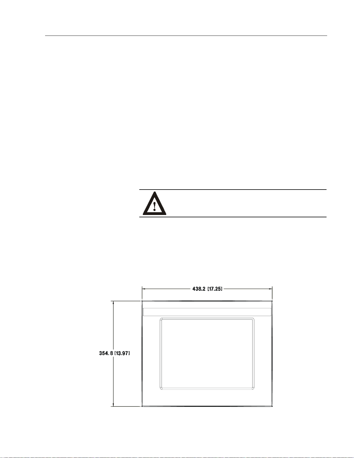
Industrial 15" Flat Panel Monitor..................................... 3
Description........................................................................... 3
Package Contents................................................................. 4
Installing the 6185-C Flat Panel Monitor.............................. 5
Panel Mounting.................................................................... 6
Connecting the 6185-C Flat Panel Monitor........................... 11
Initial Video Setup................................................................ 15
Operating the 6185-C Flat Panel Monitor ............................. 23
Routine Maintenance............................................................ 31
Troubleshooting ................................................................... 32
Appendix A: Touchscreen Serial Interface........................ 34
Description........................................................................... 34
Setting Up the Touchscreen Interface.................................... 34
Performing a Calibration...................................................... 36
Appendix B: HD-15 Video Cable....................................... 37
Appendix C: Backlight Replacement................................. 38
Replacing the Backlight........................................................ 38
Specifications...................................................................... 39
Important User Information Solid state equipment has operational characteristics differing from those of
electromechanical equipment. "Safety Guidelines for the Application, Installation, and
Maintenance of Solid State Controls" (Publication SGI-1.1) describes some important
differences between solid state equipment and hard-wired electromechanical devices.
Because of this difference, and because of the wide variety of uses for solid state
equipment, all persons responsible for applying this equipment must satisfy themselves
that each intended application of this equipment is acceptable.
In no event will Rockwell Automation be responsible or liable for indirect or
consequential damages resulting from the use or application of this equipment.
The examples and diagrams in this manual are included solely for illustrative purposes.
Because of the many variables and requirements associated with any particular
installation, Rockwell Automation cannot assume responsibility or liability for actual
use based on the examples and diagrams.
No patent liability is assumed by Rockwell Automation with respect to use of the
information, circuits, equipment, or software described in this manual.
Reproduction of the contents of this manual, in whole or in part, without written
permission of Rockwell Automation is prohibited.
Throughout this manual, we use notes to make you aware of safetyconsiderations.
ATTENTION: Identifies information about practices or
circumstances that can lead to personal injury or death,
property damage, or economic loss.
Important: Identifies information that is especially important for successful
application and understanding of the product.

Industrial 15" Flat Panel Monitor 3
Publication 6185-5.1
,QGXVWULDO
,QGXVWULDO
)
)O
OD
DW
W3
3DQHO 0RQLWRU
DQHO 0RQLWRU
The Bulletin 6185-C 15" Industrial Flat Panel Monitor offers the
following capabilities:
•Bright (172 nits) Active Matrix-TFT 1024 x 768 display
•Displays video formats from 640 x 480 to 1024 x 768
•120°H/100°V viewing angle
•NEMA 4/12 or 4X stainless steel panel
•Touchscreen options
•AC (85-264V) or DC (24V) inputs
•Plug and Play
•Full-range dimming option
ATTENTION: The equipment described in this
document generates, uses, and emits radio frequency
energy. The equipment has been tested and found to
comply with FCC Rules, Part 15, subpart J, for Class A
computing devices.
The use of non-shielded interface or power cords with
Allen-Bradley industrial monitors is prohibited.
Description

4Industrial 15" Flat Panel Monitor
Publication 6185-5.1
Available Options
The following options are available to the 6185-C Flat Panel Monitor:
•AC and DC power options
•NEMA 4/12 or 4X (stainless steel) front panel options
•Touchscreen option
•Video cable options
•Power cord options
The monitor shipping carton contains the following items:
•Monitor
•Monitor adjustment utility on floppy diskette
•Package of mounting hardware
•AC power cord (optional)
•Video cable (optional)
•This user manual
A 6185-C Flat Panel Monitor with a touchscreen option is shipped with
these additional items:
•Supporting software and manuals
•RS-232 serial extension cable (optional)
Unpacking the Unit
Before unpacking a new monitor, inspect the shipping carton for
damage. If damage is visible, immediately contact the shipper and
request assistance. Otherwise, proceed with unpacking.
Note:
Make sure you keep the original packaging for the monitor
in case you need to return the monitor for repair.
Package Contents

Industrial 15" Flat Panel Monitor 5
Publication 6185-5.1
This section describes how to install the monitor.
Before Installation
When installing the unit, it is important to consider environmental
factors at the site that could affect performance as well as possible
effects from equipment operation on personnel and nearby equipment.
Following the guidelines will help ensure that the monitor will provide
safe and reliable service.
•Ensure that sufficient power is available from a single phase AC
outlet at the site.
•Ensure that sufficient space is available around air inlets and outlets
to provide the circulation necessary for cooling. Never allow air
passages to become obstructed.
•Ensure that the ambient air temperature will not exceed the
specified maximum temperature. A heat exchanger, air conditioner, or
user-supplied fan to stir the air may be required to meet this condition
in some installations.
Note:
Remember that heat rises—many times the temperature at
the top of an enclosure is much higher than the rest of the
enclosure if the air is not circulating.
Important:
This monitor is designed to operate at a range of extremes,
however it is not good design practice to continuously
operate the monitor at the highest end of the specified
temperature range.
While the product will operate at its highest specified
temperature, the overall life span of any electronic device is
shortened when it operates at its highest rated temperature.
•Leave the monitor’s enclosure or cover in place at all times during
operation. The cover affords protection against high voltages inside
the monitor and inhibits radio-frequency emissions that might
interfere with other equipment.
•The Federal Communications Commission has prepared a pamphlet
that addresses the problem of radio frequency interference to radio
and television reception, which should be consulted in case of
problems with such interference. This publication, “How to Identify
and Resolve Radio/TV Interference Problems” (Stock #004-000-
00345-4) may be obtained from the US. Government Printing Office,
Washington, DC 20402.
Installing the 6185-C Flat
Panel Monitor

6Industrial 15" Flat Panel Monitor
Publication 6185-5.1
•Determine the minimum and maximum ambient humidity for the
monitor by consulting the specification sheets at the back of this
manual. Ensure that the humidity of the ambient air will not exceed
these limits. In very dry environments, static charges build up very
readily. Proper grounding of the equipment through the AC power
cord can help reduce the likelihood of static discharges, which may
cause shocks and damage electronic components.
When properly installed, the 6185-C Flat Panel Monitor is designed to
provide protection against water and dust to NEMA 4 and NEMA 12
standards.
No slides or shelves are required because the 6185-C Flat Panel Monitor
is designed to be supported by the panels in which it is installed.
Figure 1
Generic Panel Mount Diagram
Tools Needed
In addition to the tools required to make the cutout, you will need the
following tools:
•3/8” Deep Well Socket
•1/4” Drive Extension - 6” or longer
•1/4” Drive Ratchet or 1/4” Drive Torque Ratchet
Panel Mounting

Industrial 15" Flat Panel Monitor 7
Publication 6185-5.1
Panel Mounting Guidelines
Observe the following precautions before installing the unit in a panel:
•Confirm that there is adequate space behind the panel. Remember to
allow extra space (0.5 in. or 12.7 mm behind and on each side) for air
circulation. A cabinet with a minimum depth of 4.4 in. (112 mm) is
sufficient.
•Take precautions so that metal cuttings do not enter any components
that are already installed in the panel.
•Supporting panels should be at least 14 gauge to ensure proper
sealing against water and dust and to provide proper support. The
mounting hardware supplied accommodates panels up to 0.25 in.
(6.35 mm) thick.
Note:
Supporting panels must be cut and drilled to
specifications prior to installation.
ATTENTION: Failure to follow these warnings may
result in personal injury or damage to the panel
components.
Dimensions
This section provides diagrams you need to follow to install the unit.
Figure 2
Dimensions (Front View)

8Industrial 15" Flat Panel Monitor
Publication 6185-5.1
Figure 3
Dimensions (Side View)
Figure 4
Dimensions (Back View)

Industrial 15" Flat Panel Monitor 9
Publication 6185-5.1
Panel Mounting Procedure
1. Cut and drill the panel (refer to following figure). Units are in mm
[inches].
Note:
Use #10-32 self-locking nuts for mounting.
Figure 5
Panel Mounting Cutout
2. If access to the side of the monitor is not available following
installation, attach the power and video cables to the side of the
monitor at this time.
3. Install the monitor in the prepared cutout. Refer to the figure on this
page.

10 Industrial 15" Flat Panel Monitor
Publication 6185-5.1
4. Install lock nuts and washers, supplied with the monitor, behind the
holes running along the sides and top/bottom of the cutout in the
panel.
5. Tighten all mounting bolts evenly to a torque of 24 inch-pounds.
ATTENTION: Mounting nuts must be tightened to a
torque of 24 inch-pounds to provide panel seal and avoid
potential damage. Rockwell Automation assumes no
responsibility for water or chemical damage to the
monitor or other equipment within the enclosure due to
improper installation.

Industrial 15" Flat Panel Monitor 11
Publication 6185-5.1
The side panel of the 6185-C Flat Panel Monitor has connectors for
attaching cables to accomplish the following:
•Connecting to a host video source (HD-15 VGA connector)
•Connecting to a host touchscreen control port (DE-9 connector)
(optional)
•Connecting to AC power (IEC connector) or DC power (terminal
block)
Note:
Some connectors on your monitor may differ from the
following figure.
The following figure illustrates the standard configuration for the 6185-C
Flat Panel Monitor.
Figure 6
Side Panel
Connecting the 6185-C
Flat Panel Monitor

12 Industrial 15" Flat Panel Monitor
Publication 6185-5.1
Connecting the Video Source
The video connection to the host is made through a HD-15 (female)
connector located on the side panel.
Note:
For more information on using an HD-15 video cable to
connect to the host computer, refer to Appendix B
(Page 37).
To establish a signal using the HD-15 connector:
1. Obtain a shielded, properly terminated video cable of length as short
as possible. Longer cables (up to approximately 50 feet in some
cases) may be used, provided they are properly constructed. Your
package may include a six-foot or 15-foot video cable, if specified.
2. Connect one end of the cable to the female HD-15 video input
connector on the side panel of the monitor.
3. Connect the other end to the output of any IBM-compatible VGA
adapter or other video generator.
Note:
You may connect the monitor to video generators that
do not conform to VGA standards. The main
requirement is that the generator provides analog RGB
video signals (0.714V above reference black into 75
ohms) and separate horizontal and vertical sync signals.
Connecting the Touchscreen Interface (Touchscreen
Option)
The serial touchscreen interface connection to the host is made through
an RS-232 DE-9 (female) D-shell connector located on the side panel.
The optional touchscreen provides a high-resolution touch input system.
Driver software included with the package allows the touchscreen to
function with many popular DOS and Windows®-based industrial
applications as a pointing device (mouse).
Note:
Refer to the manual included with the touchscreen option
and Appendix A of this manual (page 34) for additional
details on the installation and operation of the touchscreen.

Industrial 15" Flat Panel Monitor 13
Publication 6185-5.1
To connect the touchscreen:
1. For units with the touchscreen option, make sure you have one of the
optional serial cables.
2. Connect one end of the touchscreen serial cable to the T/S port
connector on the side of the monitor.
3. Connect the other end to any communications port on the host
computer.
4. Tighten the captive screws on the cable connector to secure it.
Connecting AC Power (AC Power Option)
The 6185-C Flat Panel Monitor with AC power option requires a single-
phase power supply providing 85 to 264V AC at 47 to 70 Hz. Power
must be available at a grounded three-pin outlet located nearby.
Whenever possible, connect the monitor to the same AC source that
supplies the computer.
To connect AC power to the monitor:
1. Turn off the main switch or breaker.
2. Use the ground terminal of the monitor (below the power and T/S
connectors) to establish a chassis-to-earth ground connection.
Secure one end of a ground strap to the ground terminal. Connect
the other end of the ground strap to a good earth ground.
The ground terminal is an M5 screw.
ATTENTION: Chassis ground must be connected for
safe operation of the monitor. The AC receptacle on the
monitor is a 3-wire type with chassis ground pin, and the
mating AC cord supplied is a 3-wire type, designed for
connection to a grounded 3-pin AC outlet. However, a
properly ground AC outlet is not always available, and
grounding using a 3-wire cord can easily be defeated. If
you fail to ground the monitor properly, the setup may
result in personal injury from electrical shock or damage
to the equipment.
3. Connect the socket end of the AC power cord to the mating IEC
connector on the rear panel of the monitor. Position the power cord
retaining clip attached to the rear panel connector over the cord’s
socket to secure it in place.

14 Industrial 15" Flat Panel Monitor
Publication 6185-5.1
4. Connect the plug end of the AC power cord to the main outlet.
5. Restore AC power to the outlet.
Connecting DC Power (DC Power Option)
The 6185-C Flat Panel Monitor with DC power option requires a DC
power supply providing 18 to 32V DC.
To connect DC power to the monitor:
1. Turn off the main switch or breaker.
2. Use the ground terminal of the monitor (below the power and T/S
connectors) to establish a chassis-to-earth ground connection.
Secure one end of a ground strap to the ground terminal. Connect
the other end of the ground strap to a good earth ground.
The ground terminal is an M5 screw.
ATTENTION: Chassis ground must be connected for
safe operation of the monitor. The DC screw terminals on
the monitor have a chassis ground pin. However, some
DC sources may not provide a proper ground path. If you
fail to ground the monitor properly, the setup may result
in personal injury from electrical shock or damage to the
equipment.
3. Connect the +VDC wire to the “+V” screw terminal. Connect the -
VDC wire to the “-V” screw terminal. Connect the power source
ground wire to the GND screw terminal. Tighten down the screw
terminals.
4. Restore DC power.

Industrial 15" Flat Panel Monitor 15
Publication 6185-5.1
The 6185-C Flat Panel Monitor is configured at the factory, but typically
requires initial adjustments to ensure the best screen image. Rockwell
Automation provides the Flat Panel Monitor Adjustment Utility with
each flat panel monitor to assist you in adjusting the monitor settings.
Workstation Setup
There are two important aspects of your workstation setup that affect the
screen image of the 6185-C Flat Panel Monitor:
•Monitor type
•Video resolution
•Video refresh rate
You need to verify that your workstation is using the appropriate settings
for these before you begin to adjust the monitor itself.
Note:
You verify and change these settings for your workstation
using the Windows Control Panel. Select the Start button
and select Settings to access Control Panel. In Control
Panel, select Display to access monitor settings. The
options on the Control Panel screens may vary depending
on your video driver.
Monitor Type
If you are using Windows 95 or Windows 98 and your video card
supports it, you should enable your workstation to detect Plug & Play
monitors and select Plug and Play as the monitor type. To access these
settings from Control Panel, select the Settings tab and select either
Change Display Type or Advanced Properties. Windows will detect the
flat panel monitor and configure your workstation with the appropriate
settings.
If your video card does not support Plug and Play, or if you are using
Windows NT, you should select “Super VGA 1024x768” from the list of
standard monitor types.
Note:
This monitor has a flat panel display, but it uses the
workstation's analog VGA interface. Because of this, some
setup screens may indicate that the monitor is operating as a
CRT (analog) device, rather than a flat panel (digital)
device.
Video Resolution
Flat panel monitors are fixed resolution devices and the image looks best
when operated at their native resolution. If you switch the resolution of
this monitor from 1024x768 resolution, the display may look slightly
distorted due to replication techniques to display the full screen.
Initial Video Setup

16 Industrial 15" Flat Panel Monitor
Publication 6185-5.1
The following table lists the amount of video memory you need to run to
each video mode:
Table A
Video Memory Requirements
Resolution Color Mode Video Memory
640x480 256 colors (8 bit) 0.4 Mb
High color (16 bit color) 0.7 Mb
True Color (24 bit color) 1.0 Mb
800x600 256 colors (8 bit) 0.6 Mb
High color (16 bit color) 1.0 Mb
True Color (24 bit color) 1.5 Mb
1024x768 256 colors (8 bit) 0.9 Mb
High color (16 bit color) 1.7 Mb
True Color (24 bit color) 2.4 Mb
Note:
The 6185-C Flat Panel Monitor displays up to 256k colors
(18-bit color). Because most workstations only support 8-
bit, 16-bit, or 24-bit color, you must operate the monitor in
True Color mode (24-bit color) to utilize the full color
range of the monitor. The monitor will interpret the colors
correctly.
Video Refresh Rate
Unlike CRT monitors, there is no benefit to operating a flat panel
monitor at higher vertical refresh rates. It is best to select 60Hz.
Changing the Resolution and Refresh Rate
You can verify and change the video settings for your workstation using
the Windows Control Panel. Select the Start button and select Settings to
access the Control Panel. Then select Display from the Control Panel to
access display settings.

Industrial 15" Flat Panel Monitor 17
Publication 6185-5.1
Common Flat Panel Video Adjustments
The 6185-C Flat Panel Monitor provides controls to adjust the following
aspects of the monitor video display:
•Horizontal and vertical position
•Horizontal size of the display
•Clock phase
•Brightness and contrast
Importance of Correctly Setting Up the Monitor
If you do not correctly set up the flat panel monitor, the image may
appear correct when you view the Windows Desktop (the screen
displayed initially displayed when Windows starts). However, when you
display an application with certain colors or patterns, you may notice
noisy video or jitter problems at that time.
For example, if the horizontal or vertical position of the display is not
adjusted correctly, one edge of the screen image may extend beyond the
side of the monitor screen.
The horizontal size and clock phase adjustments are especially important
for flat panel monitors. If the horizontal size setting is not properly
adjusted, the screen image may contain vertical shaded bars or the image
may be too wide or too narrow for the screen. If the clock phase setting
is not properly adjusted, the screen image may be “jittery.”
Figure 7
Monitor Video Adjustments
You may also need to adjust the brightness or contrast of the screen
image based on the conditions of the location in which the monitor is
installed.

18 Industrial 15" Flat Panel Monitor
Publication 6185-5.1
Note:
The adjustment utility delivered with this flat panel monitor
is designed to present the "worst case" scenario for graphic
display. It shows a range of colors and presents a pattern
you can use to ensure that the monitor is adjusted properly.
Adjusting Settings
Use these instructions to adjust the video settings to achieve the best
screen image.
Note:
These instructions use the Select, Up, and Down buttons on
the back panel of the monitor. For more information on the
location and operation of the controls on the monitor, refer
to Page 24.
Step 1 - Start the Adjustment Utility
1. Insert the diskette provided with the monitor in the floppy drive of
the host computer.
2. Start the Flat Panel Monitor Adjustment utility using the instructions
on the diskette label.
The utility displays an image on the screen to assist you in adjusting
the monitor settings.
Note:
The utility may take several seconds to display the
screen image.
Step 2 - Display the on-screen menu and verify workstation settings
1. Press the Select button on the back panel of the monitor to display
the on-screen menu.
2. Highlight the System option and press Select.
3. Verify that you are running with the desired resolution and a vertical
refresh rate of 60Hz or 75Hz.
4. If necessary, change the resolution or vertical refresh rate for the
workstation using Control Panel. Refer to Page 15.

Industrial 15" Flat Panel Monitor 19
Publication 6185-5.1
Step 3 - Start the auto-adjust feature
1. Highlight the Auto Adjust option and press Select. The monitor will
attempt to adjust the settings properly based on the current signal.
This process may take up to 20 seconds, during which time the
screen will be dark.
2. Do one of the following:
•If the display looks acceptable, go to Step 10.
•If the display does not look acceptable, repeat the auto adjust
process two or three more times. If the display still does not look
acceptable, proceed to the next step.
Step 4 - Adjust the horizontal size
1. Highlight the Image Position option on the main menu and press the
Select button. Then highlight the Horizontal Size option and press
the Select button.
2. Adjust the horizontal size until the pattern of vertical shaded bars
disappears (refer to Figure 7). You should see each individual
vertical line in the setup image across the screen. Refer to the
following figure:
Note:
If you are running the monitor with a resolution other than
1024x768 (native mode), you will not see individual lines
in all cases. This is a result of the replication techniques
used to display the full image.
You can use the white border around the setup screen to set
up the horizontal size correctly.
Figure 8
Horizontal Size Adjustment

20 Industrial 15" Flat Panel Monitor
Publication 6185-5.1
Note:
Since you have not yet adjusted the clock phase of the
monitor, it is possible that the lines may appear
consistently fuzzy across the image. You may need to
complete the adjustment process before the vertical
lines are sharp and crisp.
3. Use the Up and Down buttons to adjust the horizontal size until the
vertical shaded bars disappear and the screen image fits the display
precisely. Then press the Select button.
Note:
The vertical size is set automatically by the monitor
according to the video signal.
Step 5 - Adjust the horizontal position
1. Highlight the Image Position option on the main menu and press the
Select button. Then highlight the Horizontal Position option and
press the Select button.
2. Adjust the horizontal screen position so that the white border line is
visible on both sides of the image. Press the Select button.
Note:
If the horizontal size and position are adjusted
correctly, you should be able to adjust the horizontal
position one adjustment to the left or right and the
white border line should move off the edge of the
screen. If this does not occur, you may need to repeat
the horizontal size adjustment step.
Step 6 - Adjust the vertical position
1. Highlight the Image Position option on the main menu and press the
Select button. Then highlight the Vertical Position option and press
the Select button.
2. Adjust the vertical screen position so that the white border line is
visible on the top and bottom of the image. Press the Select button.
Table of contents
Other Rockwell Automation Monitor manuals

Rockwell Automation
Rockwell Automation 6181P User manual

Rockwell Automation
Rockwell Automation Allen-Bradley 6185-H User manual

Rockwell Automation
Rockwell Automation Allen-Bradley VersaView 6300M Series User manual

Rockwell Automation
Rockwell Automation Allen-Bradley 6176M-15VN User manual

Rockwell Automation
Rockwell Automation Allen-Bradley 6186M Series User manual

Rockwell Automation
Rockwell Automation 6185-D User manual