2Rockwell Automation Publication 6300V-IN004A-EN-P - November 2022
Remote Video Link Receiver for 6300B Box PCs and 6300T Box Thin Clients Installation Instructions
European Union Directive and UKCA Compliance
This equipment meets the European Union Directive and UK requirements when installed within the European Union or EEA regions and have the CE marking. A copy of the
declaration of the conformity is available at rok.auto/certifications.
Unpack your RVL Receiver
Your RVL receiver ships with the following items:
• RVL receiver, 6300V-RVLDV-RX
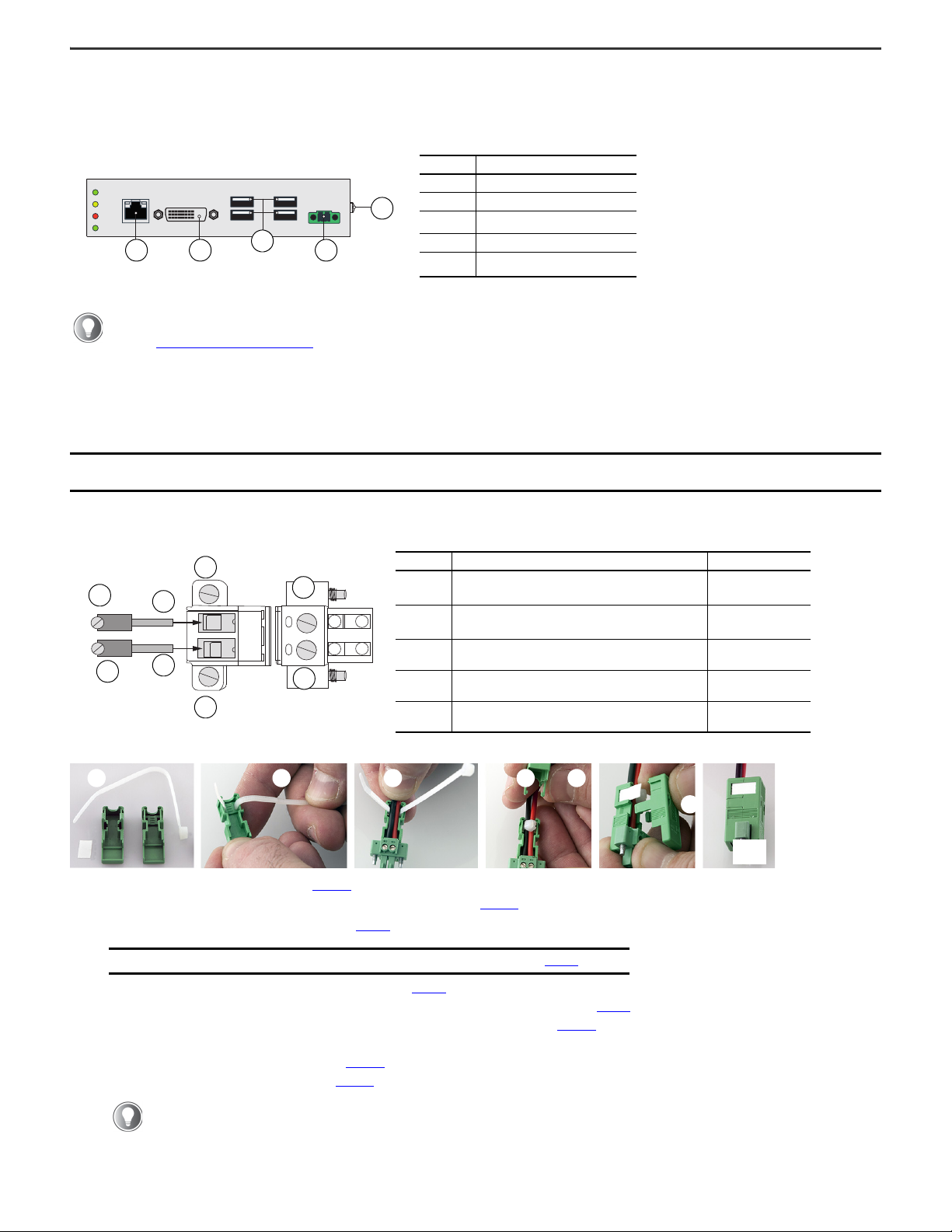
• DC terminal block kit
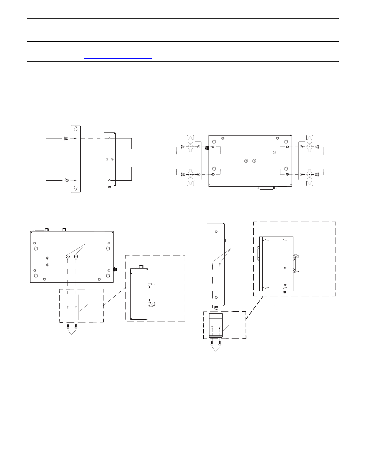
•Mountingkits
- Book mount kit: bracket (quantity 1) and screws (quantity 2)
- Wall mount kit: brackets (quantity 2) and screws (quantity 4)
- DIN rail mount kit: rail hook (quantity 1) and screws (quantity 2)
Installation Site Guidelines
Follow these installation site guidelines to make sure that your RVL receiver provides service with excellent reliability.
• When choosing the installation site, consider the following:
- The site must have sufficient power.
- The site must be indoors your RVL receiver to direct sunlight.
• The maximum operating ambient temperature of your RVL receiver is 50 °C (122 °F).
- Measure the ambient temperature 5 cm (2 in.) away from all cooling openings.
- Make sure all cooling openings/grids are not obstructed to confirm proper airflow.
- Your RVL receiver can be stored in a surrounding air temperature range of -5…+60 °C (23…140 °F).
- The relative humidity (RH) of the ambient air must be 80% non-condensing when your RVL receiver is operating or being stored.
• When planning the layout and connections of your RVL receiver:
- For electromagnetic compatibility (EMC), place the cables away from the source(s) of electric noise (such as power cables, high-voltage power sources,
transformers, electric welders, or radio frequency (RF) sources) that could compromise the quality of the signal.
- Do not place the RVL cable together with power cables unless an adequate insulation class is provided.
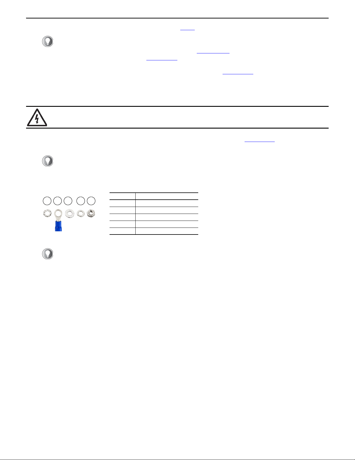
- The chassis of your RVL receiver must be connected to ground via the ground screw.
- Consider the placement of required components and the maximum length of the cables to connect your RVL receiver to other components. See Required
Equipment.
Required Equipment
To complete the installation of your RVL receiver, the following equipment is required.
ATTENTION: This equipment is intended to operate in an industrial or control room environment, which uses some form of power isolation from the
public low-voltage mains. Some computer configurations cannot comply with the EN 61000-3-2 Harmonic Emissions standard as specified by the EMC
Directive of the European Union. All I/O cables must be used only indoors.
Before you unpack your RVL receiver, inspect the shipping carton for damage. If damage is visible, immediately contact the shipper and request assistance.
If there is no visible damage, proceed with unpacking.
WARNING: This RVL receiver is:
• suitable for use in CLASS I, DIVISION 2, GROUPS A, B, and D Hazardous Locations or Non-hazardous Locations only.
• considered open equipment which means that it may only be integrated in housings or cabinets where the front panel can be accessed for operation.
Components Cables Tools
• Industrial monitor
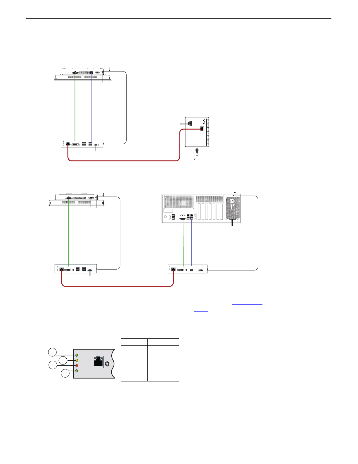
• Industrial PC with integrated transmitter or RVL transmitter
(6300V-RVLDV-TX) and Industrial PC
• DIN Rail (for DIN rail-mount installation only)
• 24V DC (input voltage 18…32V DC) power supply (1)
(1) The power supply must: (a) satisfy the requirements of a safe extra low voltage (SELV) in accordance with IEC/EN/DIN EN/UL60950-1 and (b) fulfill the requirements NEC Class 2 LPS in accordance with
IEC/EN/DIN EN/UL60950-1. Connect the system with a cable cross-section of 0.75 • 1.5 mm2(from AWG18 to AWG16 suitable in a minimum of 75 °C (167 °F).
• DVI cable, 11 m (36 ft) maximum length (2)
• USB 2.0 cable, 11 m (36 ft) maximum length (2)
• RVL (Cat. 5E/Cat. 6 A connection) cable, 100 m (328 ft)
maximum length, quantity 1
(2) Two cables are required if your installation requires a separate RVL transmitter (6300V-RVLDV-TX).
For wall mount, shelf mount, or DIN rail attachment:
• Drill and 4 mm drill bit
• #2 Phillips screwdriver
• M4x20 stainless steel screws, quantity 4
For DC power connector assembly and ground wire installation:
•2.5mmhexscrewdriver
• Wire stripper, cutter, and crimper tool
•Cuttingpliers
• Safety glasses