Rockwood 31565 User manual

3PC MICROMETER SET
INSTRUCTIONS
Item #31565

2Eastwood Technical Assistance: 800.544.5118 >> techelp@eastwood.com
The ROCKWOOD 3 PIECE MICROMETER SET relies on a proven, straightforward design to provide
many years of service. They feature rugged, all metal construction for maximum durability and
accuracy. Easy to use with a range that is ideal for most average automotive applications.
CONTENTS
(1) 0-1” range, 0.001” Micrometer
(1) 1-2” range, 0.001” Micrometer
(1) 2-3” range, 0.001” Micrometer
(1) 1” Gauge Block
(1) 2” Gauge Block
(1) Adjustment Wrench
(1) Heavy Duty Blow Molded Storage Case
SPECIFICATIONS
• Hardened, Mirror Polished Carbide Anvil and Spindle Faces
• SAE Ranges from 0 to 1”, 1” to 2” and 2” to 3”
• 0.001” Increments
• 5/16”, 1-11/4” and 1-5/8” Throat Depths
READ INSTRUCTIONS
• Thoroughly read and understand these product instructions before using this tool.
• Keep these product instructions for future reference.

To order parts and supplies: 800.345.1178 >> eastwood.com 3
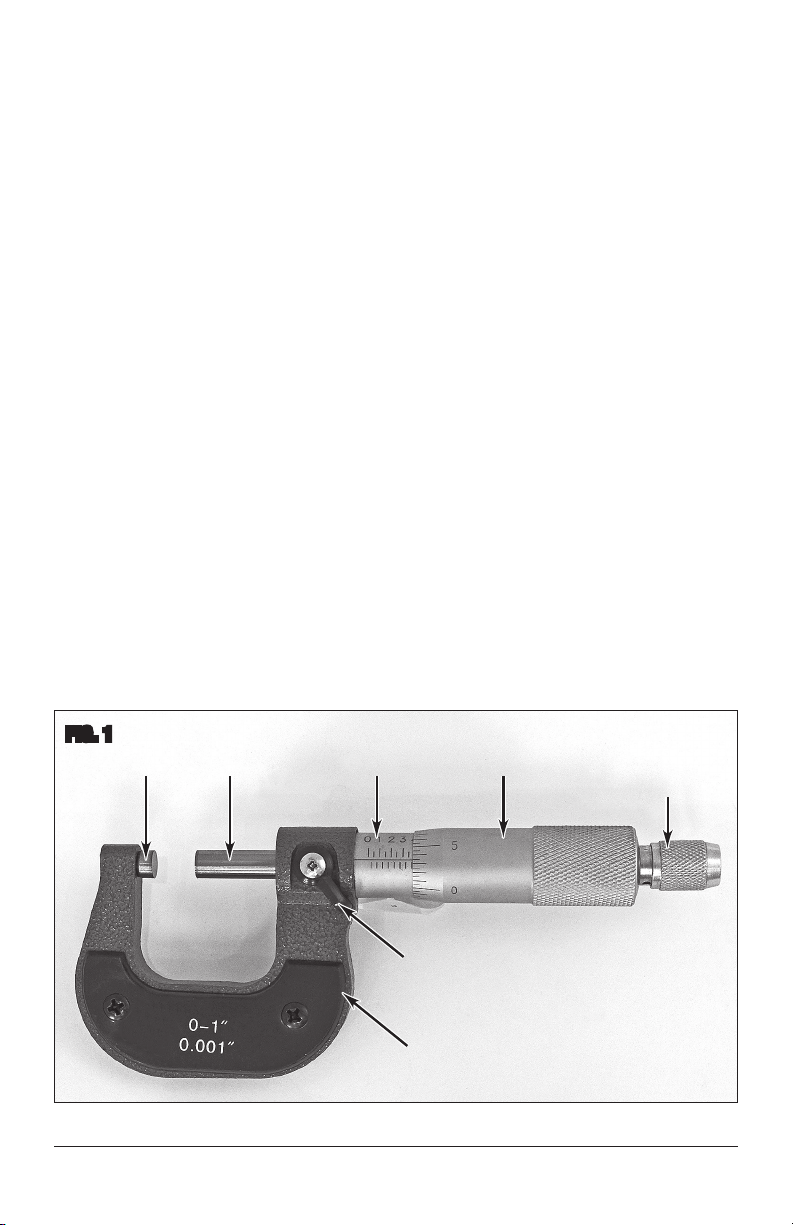
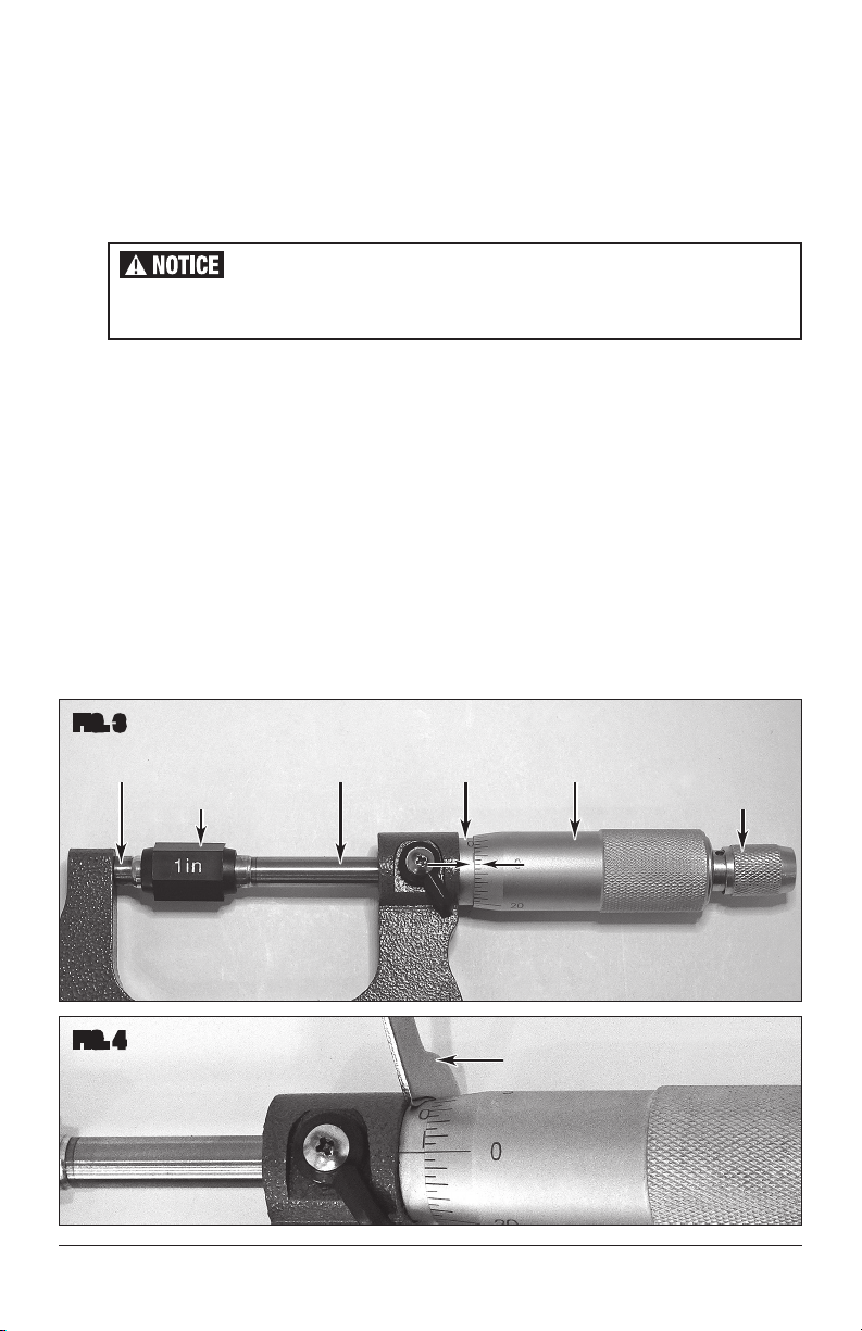
✓
FIG. 1
Frame
Ratchet
Knob
ThimbleSleeveSpindleAnvil
Lock Lever
✓
✓
✓
✓
✓
✓
OPERATION
The accuracy of Micrometer measurement can be adversely affected by temperature. Micrometer and
part temperatures of 72°F [22°C] are ideal while warmer or colder extremes will cause expansion or
contraction which can produce inaccurate results.
• Place the Micrometer in the palm of a hand, be sure the Spindle is unlocked, then rotate the
Thimble to open it slightly beyond the dimension of the part to be measured.
• Using care not to scratch the mirror polished Anvil and Spindle surfaces, place the part against
the Anvil first, then gently turn the Spindle inward until it makes contact with the part.
• Use only the Ratchet Knob to exert pressure on the part allowing 3 ratchet clicks to denote proper
tension. The dimension can now be read.
• To lock the Spindle at the desired dimension for easier reading, rotate the Locking Lever
15° Clockwise.
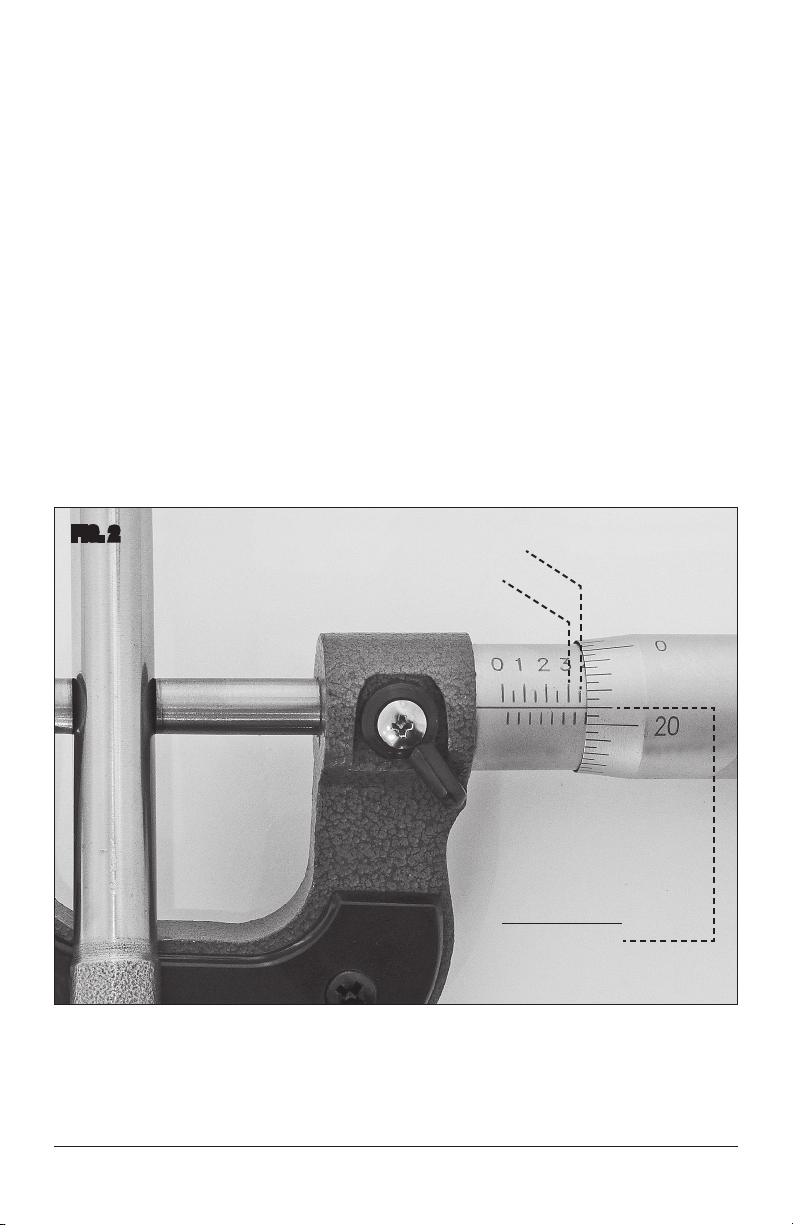
READING THE MICROMETER
THE SLEEVE
• The Micrometer Sleeve is fixed and does not move (FIG 1).
• It has 10 markings, each of these markings is equal to 0.100” or 1/10” (1 tenth of an inch).
Viewed another way; The space on the sleeve between “0” and “1” equals .100”, the space
between “1” and “2” equals 0.200” and so on to 8, 9, 0.
• Each of these 10 markings is divided into 4 equal parts. (Note that 2 markings are above the
line while 2 are below).
• Each of those 4 markings is equal to .025” or 1/40” (1 40th of an inch).

4Eastwood Technical Assistance: 800.544.5118 >> techelp@eastwood.com
THE THIMBLE
• The Thimble rotates about the Sleeve and moves in and out as it is turned (FIG 1).
• One complete rotation of the thimble is also equal to the smallest divisions of the Sleeve which,
of course, is 0.025” or 1/40” (1 40th of an inch).
• The Thimble is divided into five equal segments, each one with a “long” line and numbered
from “0” to “5”, “10”,”20” and back to “0”. Each of these numbered lines represents 0.005”
• Every one of the “medium” segments equals 0.001” or 1/10” (1 10th of an inch).
• The shortest lines between the “medium” 0.001” length lines represent 1/2 of 0.001 (0.0005”)
and are for approximation only.
EXAMPLE
In this example, a worn automotive valve stem is used to illustrate the sequence of determining a final
dimension of a part (FIG 2).
• The position of the Thimble edge over the Sleeve markings shows 0.300 + 2 additional marks
equaling 0.025 each which equals 0.050 for 0.350”.
• The marks on the indicted on the Thimble in relation to the horizontal line on the Sleeve is
showing 0.020 + one additional mark of 0.001 for a final dimension total of 0.371”.
FIG. 2
0.300”
0.350”
0.300
+ 0.050
+ 0.020
+ 0.001
= 0.371
Final Dimension

To order parts and supplies: 800.345.1178 >> eastwood.com 5
MAINTENANCE
• Before each use, inspect the condition of the Micrometer for any accumulated dirt, damage
or corrosion that may affect operation and accuracy.
• After each use, be sure to inspect and clean any contaminates from the mirror polished
surfaces of the Anvil and Spindle.
• Keep the Micrometer stored in a clean, dry location, in the supplied case. Periodically coat bare
metal with a rust preventative coating such as a light machine oil.
Micrometers will require periodic calibration and adjustment with use. They are as follows:
• Zero the Thimble to the Sleeve:
-Place the appropriate sized (1” or 2”) Gauge block against the Anvil then gently close
the Spindle against it using the Ratchet Knob (FIG 3).
-Observe the “0” line of the Thimble in relation to the horizontal line on the Sleeve.
The “0” of the Thimble should align with it. If not, it must be adjusted.
-Hook the large end of the included Adjustment Wrench into the hole in the back side of
the Sleeve and very gently turn it Clockwise or Counterclockwise as required to bring it
into alignment (FIG 4).
FIG. 3
FIG. 4
✓
Ratchet
Knob
ThimbleSleeveSpindleAnvil
✓
✓
✓
✓
Gauge
Block
✓
✓
✓
Adjustment Wrench
✓
Dropping the Micrometer can have an adverse effect on accuracy.
Do Not drop the Micrometers or allow them to fall.

6Eastwood Technical Assistance: 800.544.5118 >> techelp@eastwood.com
• Adjust Thimble Knob Ratchet Tension:
-Hook the small end of the included Adjustment Wrench in the hole on the side of the
Thimble Knob Ratchet then increase or decrease tension using a small screwdriver in
the slot on the end of the Spindle Ratchet Knob (FIG 5).
• Set Thimble Thread Lash:
-Remove the Thimble from the Micrometer completely by unthreading it fully and exposing
the threaded portion of the Sleeve (FIG 6).
-Hook the large end of the included Adjustment Wrench in the hole on the side of the collar,
then decrease lash by turning it in slightly (FIG 6). Reassemble the Spindle to the
Micrometer to test lash and rotational resistance. Readjust if required.
FIG. 5
FIG. 6
Adjustment Wrench
✓
Ratchet Knob
✓
Thimble
✓
Adjustment Wrench
✓
Sleeve
✓
Thimble
✓
Spindle
✓

To order parts and supplies: 800.345.1178 >> eastwood.com 7

© Copyright 2016 Easthill Group, Inc. 11/16 Instruction item #31565Q Rev 1
If you have any questions about the use of this product, please contact
The Eastwood Technical Assistance Service Department: 800.544.5118 >> email: techelp@eastwood.com
PDF version of this manual is available online >> eastwood.com/31565manual
The Eastwood Company 263 Shoemaker Road, Pottstown, PA 19464, USA
US and Canada: 800.345.1178 Outside US: 610.718.8335
Fax: 610.323.6268 eastwood.com
ADDITIONAL ITEMS
#31568 Digital 6” Caliper
#28038 Sheet Metal Gauge
Table of contents
Other Rockwood Measuring Instrument manuals
Popular Measuring Instrument manuals by other brands

Hanna Instruments
Hanna Instruments HI 723 quick start guide

Megger
Megger IDAX 300 user guide

Horiba Scientific
Horiba Scientific LAQUA F-73G Setup and lnstruction manual

KROHNE
KROHNE OPTISONIC 7300 quick start

Endress+Hauser
Endress+Hauser Promag installation instructions

RIDGID
RIDGID SeeSnake CS65x Operator's manual