Roger GNSS-L1G1GA-EU User manual

THE GNSS REPEATER TECHNOLOGY EXPERT
ROGER™ GNSS-L1G1GA-EU/-UK/-US
Repeater
User Manual

Version 2.0 Copyright Roger™-GPS 2019 10 01
2
Thank you for choosing Roger™-GPS Ltd for your requirements. We appreciate your support and are certain that our
product will serve you reliably. This product is designed to provide many years of reliable service, provided it is used as
intended and taken care of. This user manual will assist you in assembly and general operation of this product.
It is not our intent to teach you about GNSS satellite navigation. It is assumed that you are an experienced user of
satellite navigation products and services with the relevant skills and experience necessary to use this product safely. If
after reading the following instructions, you are unsure or uncomfortable about safely using this product, we urge you
to seek additional information through our local partner or widely available GNSS and GPS information sources. Some
of the information sources are listed at the end of this manual.
ROGER™GNSS Repeater key features
1. ROGER™GNSS Repeater products are designed and manufactured in Finland.
2. ROGER™ GNSS Repeater products are carefully tested and have full two years warranty.
3. ROGER™GNSS Repeater products are CE-certified and approved worldwide by the communications
authorities e.g. in EEA countries for use as radio-licensed devices.
4. ROGER™ GNSS repeaters have a proprietary gain control system that provides up to 15dB more
signal than other systems in the market and providing up to 10 times more signal gain while still
maintaining the ETSI EN 302 645 standard.
5. ROGER™ GNSS intelligent repeaters provide more gain in difficult conditions and oscillation
(feedback) protection to protect your GNSS signals.
6. SUMMARY
–Automatic gain limitation
–Oscillation prevention with indicator
–Maximal coverage for CE approved repeater
–Seamless GNSS service and signal when moving indoors to outdoors
–Full product family with repeaters, amplifiers, splitters and power supplies
IMPORTANT!
Read carefully the contents of this manual before assembly or operation of this product.
Please check, apply and fulfil the radio licensing regulations and directives of the use of GNSS
repeaters in your country from your regulator.

Version 2.0 Copyright Roger™-GPS 2019 10 01
3
Roger-GPS Ltd. –the Company
The increasing dependence on GNSS –Global Navigation Satellite System (GPS, Glonass, Galileo, Beidou)
and their applications has placed an additional demand on them having the capability of operating both
indoors and outdoors without interruption to the data.
ROGER™GPS Ltd. is a company that specializes in GNSS (GPS) repeating technology. The ROGER™-GPS
proven system concept enables the use of GNSS repeater devices to provide services in places where it was
previously unavailable. We have a wide range of customers who always require reliable GNSS signal
reception or time synchronization; they include telecommunications providers, Public Safety Services,
Utilities, Defence, Transport, Airlines, Logistics and the companies who manufacture, sell and maintain
GNSS systems, receivers, terminals and services.
The Roger™-GPS Ltd. business concept permits the use of GNSS repeater devices and services in places
where it was not previously possible.
In September 2008 Sparklike Ltd. launched the first CE-certified GPS repeater product family approved by
the communications authorities in Finland and Sweden for use as radio-licensed device. ROGER™-GPS was
established as spin-off in February 2009 to continue the development, manufacturing and marketing of GPS
products started by Sparklike Ltd.
The private company owners of Roger-GPS Ltd. are Maktub Consulting Ltd., and Naxim Ltd.
CE CERTIFICATE, radio licensing
The Roger™-GPS L1 GPS repeater product was recertified in January 2012
according to the renewed ETSI EN 302 645 V1.1.1 (2010-03) Harmonized
European Standard. The equipment conforms to the essential requirements of
Directive 2014/53/EU (hereafter “The Radio Equipment Directive”) and EN 301
489-1 (V1.8.1), EN 301 489-3 (V1.4.1), EN 302 645 (V1.1.1).
Roger™-GPS products have been classified in NATO N-S-N code and NATO
NCAGE code.
This product can be put into service throughout the European Economic Area.
Study this documentation of use and installation instruction provided in this
manual and in your local country sales area of Roger™-GPS LTD. The user must
have the necessary frequency licence for operation in that area.

Version 2.0 Copyright Roger™-GPS 2019 10 01
4

Version 2.0 Copyright Roger™-GPS 2019 10 01
5
What is ROGER™ GNSS Repeater?
The ROGER™ GNSS repeater operates by receiving GNSS satellite signals with an externally mounted
antenna and relaying or repeating those signals to the area requiring coverage.
To use GNSS satellite devices inside your building you will need a repeater system to relay the signals from
the outside to inside where there is no coverage. A repeater is a device that receives GNSS signals and re-
transmits them to the area required. This is achieved by connecting the repeater to an externally mounted
antenna via a coaxial cable to its location inside the building.
The GNSS satellite navigation device can now receive the GNSS signal using the relayed signal from the
ROGER™ GNSS repeater. When the satellite navigation device is moved from the repeater covered area to
outdoors, the receiver seamlessly tracks the location, without resorting to the time-consuming acquisition
of GNSS almanac data (its history).
Notes:
1. The ROGER™ GNSS repeater can be used for indoor navigation, however it should be noted that the
receiver gives the position of the outdoor antenna.
2. The ROGER™ GNSS repeater fulfils the EN 302 645 V1.1.1 (2010-03) specification requirements,
meaning that it can be used throughout the EEA and in fact, world-wide.
3. The use (taking into use) of GNSS repeaters (such as ROGER™ GNSS Repeaters) in many markets
requires a radio licence to allow its use. The GNSS repeaters are intended for use by professional
business users, companies and institutes. Check the licensing regulations, conditions and how to
apply for a license from your local regulator authority before operation.
4. If the user of the GNSS repeater is an individual person, a radio license must be applied for before
the GNSS repeater is taken into use, usually available from the local regulation authority.

Version 2.0 Copyright Roger™-GPS 2019 10 01
6
Description of GNSS Repeater controls and connectors (applies to repeater GNSS-L1G1GA):
1. Gain control knob: The gain control knob is used to control the output signal level (gain variation
when turning the knob is 0-40dB) of the GNSS repeater output power.
2. DC power connector: The repeater power is supplied through the DC input connector. The
connection is reverse polarity protected with 12V DC.
3. Receiving antenna connector: The outdoor antenna is connected to the SMA input on the repeater
front panel with the coaxial cable.
a. ROGER™-GPS has product packages that include the cable.
b. Alternatively, a 50Ω custom cable can be used. On the repeater
panel, the connector is SMA female so the cable end
should terminate with a SMA male. The other end of
the cable should terminate in a TNC male, the antenna
itself being TNC female.
c. The repeater feeds +5VDC 100mA for
active outdoor antenna.
4. Status LED indicator
5. Integrated transmitter (TX) antenna inside the case.
ROGER™-GPS Repeater GNSS-L1G1GA
A single ROGER™ GNSS Repeater is enough to provide a GNSS indoor coverage area up to 1600 square
meters (m2). The modern receivers can detect the signal at very low power levels, so the distance can
reach up to 50-60 meters from the repeater’s center, depending on surrounding structures. Several
ROGER™ GNSS Repeaters can be installed in the same building. Alternatively, the signal coverage
provided by a single package can be extended with ROGER™ GNSS additional products such as line
amplifiers and signal splitters.
WHAT IS GNSS-L1G1GA (-EU/-UK/-US) PRODUCT
•1x ROGER™ GNSS Repeater unit GNSS-L1G1GA
•1x Power supply with EU or UK or US plug respectively
•1x User Manual in English

Version 2.0 Copyright Roger™-GPS 2019 10 01
7
ROGER™ GNSS repeater installation for GNSS-L1G1GA
Prior to commencing work on the installation, make a survey of the locations of the individual units,
ensuring that:
1. The antenna has good line of sight to the sky and is not shrouded or shadowed by buildings, trees
etc. and will not cause an obstruction to doors, windows, or ventilators and is located away from
any machinery HVAC, fans etc. Always connect the antenna cable before powering the repeater.
2. The antenna feeder cable can easily be routed indoors and can be properly secured to walls and or
ceilings.
3. The building protection and integrity is not compromised; i.e. breaching of fire stopped
compartments.
4. If possible, install the power supply and antenna feeder cables away from existing cables, pipes etc.
5. There is a nearby power supply to connect the repeater to.
6. The final location of the repeater allows for maximum coverage of the area.
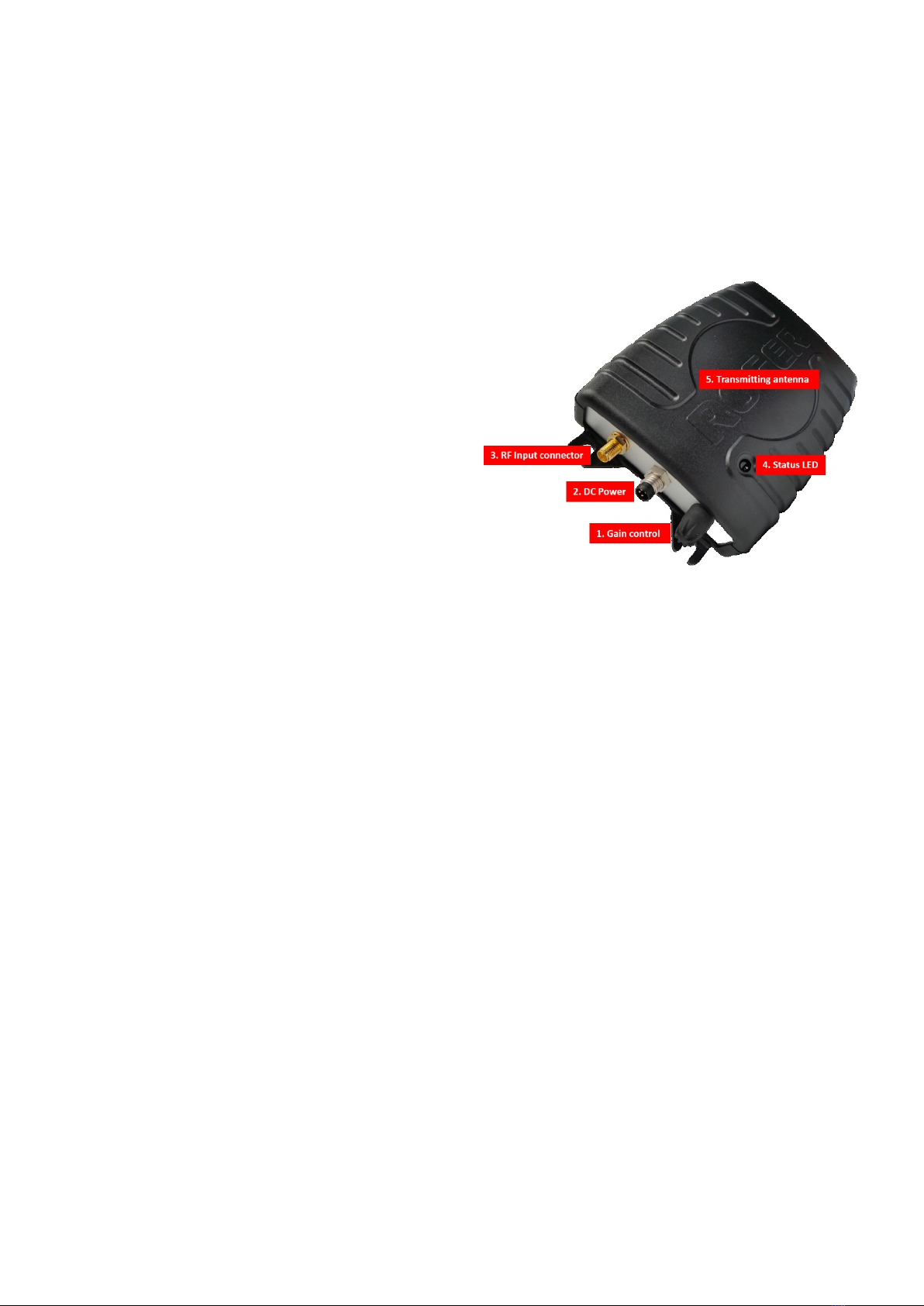
Install the GNSS repeater transmitter by fixing it to the ceiling, wall or other suitable mounting point. The
repeater has an integrated transmitter TX antenna, located internally, on the same side as the status LED.
The transmitter antenna generally radiates in the same direction as the LED. Ideally the transmitter should
be located so that any desired GNSS receiving location, for example an antenna on top of a van in a garage
has a direct line-of-sight to the repeater antenna. After installation, prior to switching on, ensure all
connections are tight.
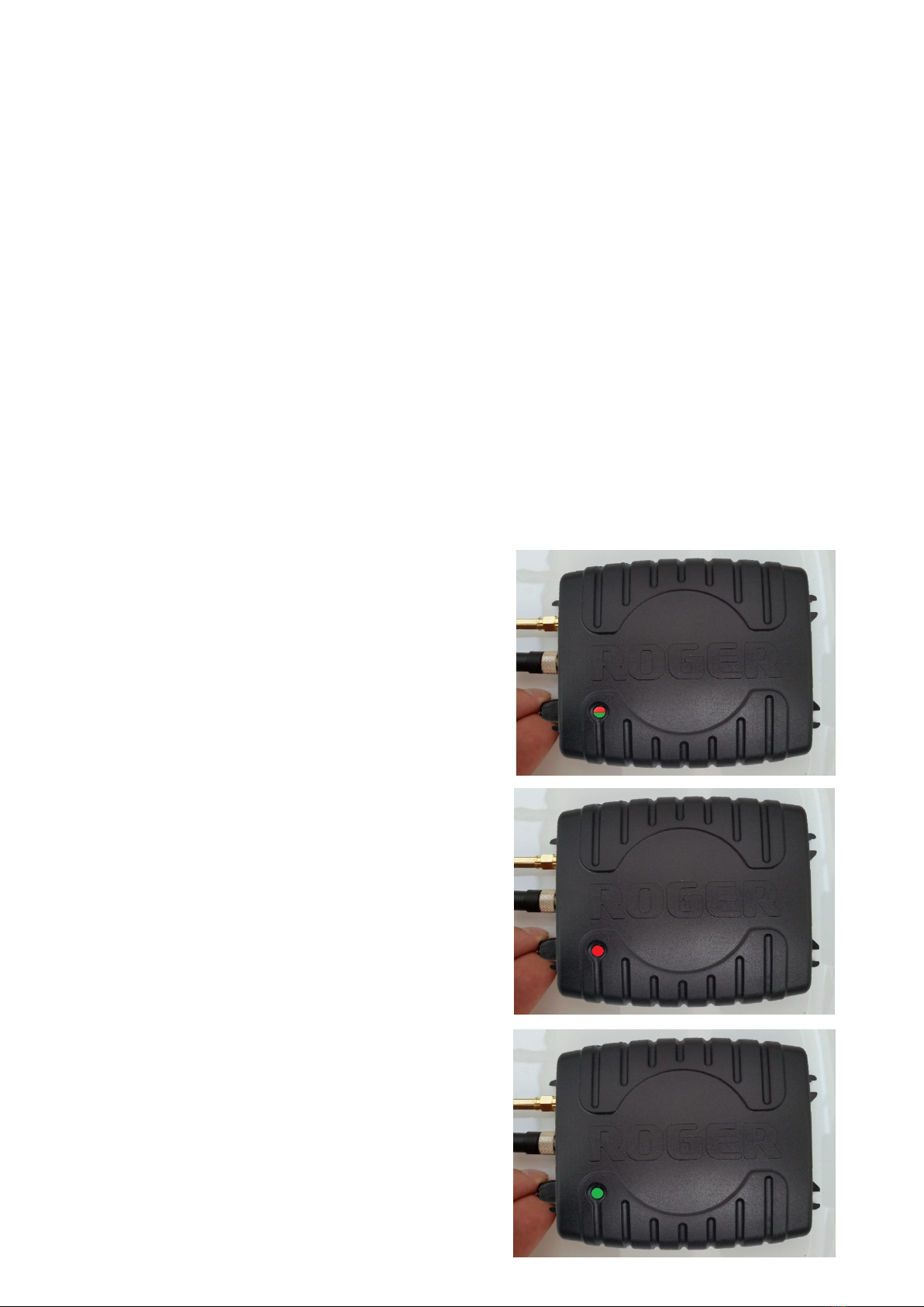
Switch the power on and the indicator LED will flash
green for between two and three seconds during the
start-up phase.
Turn the control knob in order to set the gain. A higher
gain increases the coverage of the GNSS signal.
Watch for the LED flashing to red and green, this means the
maximum power has been reached.
Turning the knob too far clockwise will result in the LED
turning red, indicating the gain setting is too high.
Constant green light indicates proper gain setting. Turning
the knob too far counterclockwise will result in the green
LED to blink indicating too low gain setting.

Version 2.0 Copyright Roger™-GPS 2019 10 01
8
The indications of the status LEDs are:
CONSTANT GREEN:
The transmitter is working correctly, no further adjustment is required.
CONSTANT RED/GREEN:
The transmitter is working at its maximum output and the gain should be reduced slightly until a
constant green is achieved.
CONSTANT RED:
The Transmitter has detected an error or interfering signal. One reason may be that the external
antenna is picking up the signal from the transmitter and a feedback oscillation is occurring; it is
strongly advised not to locate the external antenna and repeater too close together.
It may be that the power is set too high; decrease the gain on the repeater slightly.
Another common reason is that there is an interference source close to the receiving antenna.
Locating the antenna, repeater and associated cables as far away from existing wiring, machinery and
pipework will normally avoid this situation.
Troubleshooting guide:
Problem: No LED indication
Solution: Check power supply and connection.
Problem: Red light is on.
Solution: The gain setting is too high. Turn the control knob counterclockwise to decrease the gain
until the green LED is lit.
Problem: Green light flashing around 5 times per second, red light is off.
Solution: Transmitted signal level is too low. Turn the control knob clockwise to increase the gain. In
normal operation, only the green LED is continually on. In all other cases please check the
antenna connections at both ends before making any gain adjustments.

Version 2.0 Copyright Roger™-GPS 2019 10 01
9
Extending the ROGER™ repeater’s distance
from the outdoor antenna.
ROGER™ GNSS Amplifier (GNSS-A)
ROGER™ GNSS Line Amplifier is used to allow
longer cable runs and/or signal splitting to several
GNSS Repeaters.
It has a gain of +16dB and it includes a filter to
remove unwanted signals that may have entered
the cable at some point. Amplifier is powered
through the output signal cable by the ROGER™
GNSS Repeater and it passes on DC power for the
GNSS receiving antenna or another GNSS line
amplifier.
Extending the number of repeaters by
adding a Splitter 1 to 5.
ROGER™ GNSS Splitter 1 to 5 (GNSS-S)
With the ROGER™ GNSS Signal Splitter, the signal
from one external antenna can be redistributed
to up to five repeater units.
It is advisable to use a separate amplifier with the
signal splitter to ensure adequate transmission
power to all the five repeaters. If the signal is to
be transmitted to fewer than five repeaters, the
unused ports must be terminated with a 50ohm
termination. The splitter is powered through the
output signal cable by the ROGER™ GNSS
Repeater and it passes on DC power for the GNSS
receiving antenna or GNSS line amplifier.

Version 2.0 Copyright Roger™-GPS 2019 10 01
10
Extending the number of repeaters by
adding an Amplifier/Splitter
ROGER™ GNSS Amplifier& Splitter(GNSS-AS)
ROGER™ GNSS Amplifier & Splitter is a combined
signal splitter and line amplifier with an output of
+12dB (1 port) and +4 dB (2 ports) that can
transmit to up to three separate repeater units.
In order to get the amplification, the ports must
be connected as shown below. The unused ports
must be terminated with a 50ohm termination if
less than 3 repeaters are connected to GNSS-AS.
Extending the number of repeaters by
adding a Splitter 1 to 2
ROGER™ GNSS Splitter 1 to 2 (GNSS-S2)
With the ROGER™ GNSS Signal Splitter 1 to 2, the
signal from one external antenna can be
redistributed to up to two repeater units.
It is advisable to use a separate amplifier with the
signal splitter to ensure adequate transmission
power to all the two repeaters. If the signal is to
be transmitted to only one repeater, the unused
port must be terminated with a 50ohm
termination. Splitter is powered through the
output signal cable by the ROGER™ GNSS
Repeater and it passes on DC power for the GNSS
receiving antenna or GNSS line amplifier.

Version 2.0 Copyright Roger™-GPS 2019 10 01
11
ROGER™ GNSS-L1G1GA repeater technical information:
Size:
110*143*28 mm
Frequencies:
GALILEO E1: 1.57542 GHz
GPS L1: 1.57542 GHz
GLONASS G1: 1.602 GHz
BEIDOU B1: 1.5611 GHz
Weight:
165 g
Overall Gain:
> 40dB
Noise Figure:
< 2dB
Variable attenuation:
0-40dB
Impedance:
50Ω
RF Input connector:
SMA-female
Power consumption:
max 300 mA
Operating temperature:
-25 … +55°C
Power supply:
110-230VAC/+12VDC, 1600mA
Antenna power output:
+5VDC, 100mA
TX antenna gain:
max +4dBd, RHCP polarization
Indoor coverage radius:
1-50m (depends of the sensitivity of the receiver) and the gain position
Other features:
Automatic gain control
Feedback oscillation suppression Status/power LED
Output power limit –60dBm, 0,000001mW
Manual gain control
Internal transmit antenna
CE-certified
Yes
More information about GNSS specification, look at:
•http://www.gps-repeating.com/
•http://www.etsi.org/deliver/etsi_en/302600_302699/302645/01.01.01_60/en_302645v010101p.pdf

Version 2.0 Copyright Roger™-GPS 2019 10 01
12
GNSS Technology Expert ROGER™-GPS
Roger-GPS Ltd
Finnoonniitynkuja 4
02270 Espoo, Finland
www.gps-repeating.com
WARRANTY
Roger-GPS Ltd agrees that any hardware supplied under these Conditions shall be free from defects in materials and
workmanship for a period of 24months from the date of the delivery "(the Warranty Period") covering material and
workmanship. The 24 months period is calculated from the date, the products are shipped from the Byer’s
warehouse in the case that the Byer has an accounting system that keeps track on the shipment dates.
Nevertheless, the warranty period cannot exceed in any circumstances 26 months from the date of delivery from
Roger-GPS Ltd warehouse.
Roger-GPS Ltd undertakes to remedy all defects in the Products notified to it by the Buyer during the Warranty
Period by either repairing or replacing or refunding at Roger-GPS Ltd.’s option the defective Product or defective
part at Roger-GPS Ltd.’s cost.
Goods returned under this guarantee shall be delivered to Roger™-GPS Ltd at the Buyer’s expense. Before shipping
the products to Roger™-GPS Ltd, the buyer must follow the instructions (Roger-GPS RMA procedure) given by
Roger™-GPS Ltd and the inward processing directives set by the Finnish Customs.
Warranty will be void in respect of goods which in Roger-GPS Ltd.’s reasonable opinion, have been subjected to
unauthorised modification or repair, improper installation, neglect, misuse or operation in environmental
conditions outside of specified safe operating extremes. The warranty applicable to non-Roger™-GPS Ltd product
supplied by Roger™-GPS Ltd shall be limited to the warranty terms offered by the manufacturer of the product.
Roger-GPS Ltd shall not be liable to the Buyer for any consequential loss.
No warranties, expressed or implied, including but not limited to, any implied warranty of merchantability of
fitness for any purpose, are made or deemed to have been made by the Roger-GPS Ltd.
Roger-GPS Ltd shall not be responsible to the Buyer or any other party in respect of any claims arising out of the
sale of the products. Roger-GPS Ltd does not warrant the software delivered under these conditions per se but
agrees to maintain the software for a period of 90 days from the date of delivery of the relevant software.
The Buyer shall indemnify Roger-GPS Ltd against all proceedings, claims or demands in any way connected with the
Conditions brought or threatened against Roger-GPS Ltd by a third party except to the extent that Roger-GPS Ltd is
liable to the Buyer under the Conditions.
Supplier reserves all rights for product changes and upgrades.
Pictures and texts are indicative
This manual suits for next models
2
Table of contents
Other Roger Repeater manuals