Roland PR-80 Specification sheet
******
New Features Added with Ver. 1.2 of the PR-80
Version 1.2 of the PR-80 is provided with the added or changed features described below.
This leaflet provides an overview and brief descriptions of these features.
• MIDI System Settings – Dual Stream Focus
• MIDI System Settings – Video Mixer Control
• MIDI implementation
Controlling Presenter with MIDI
Using MIDI Devices
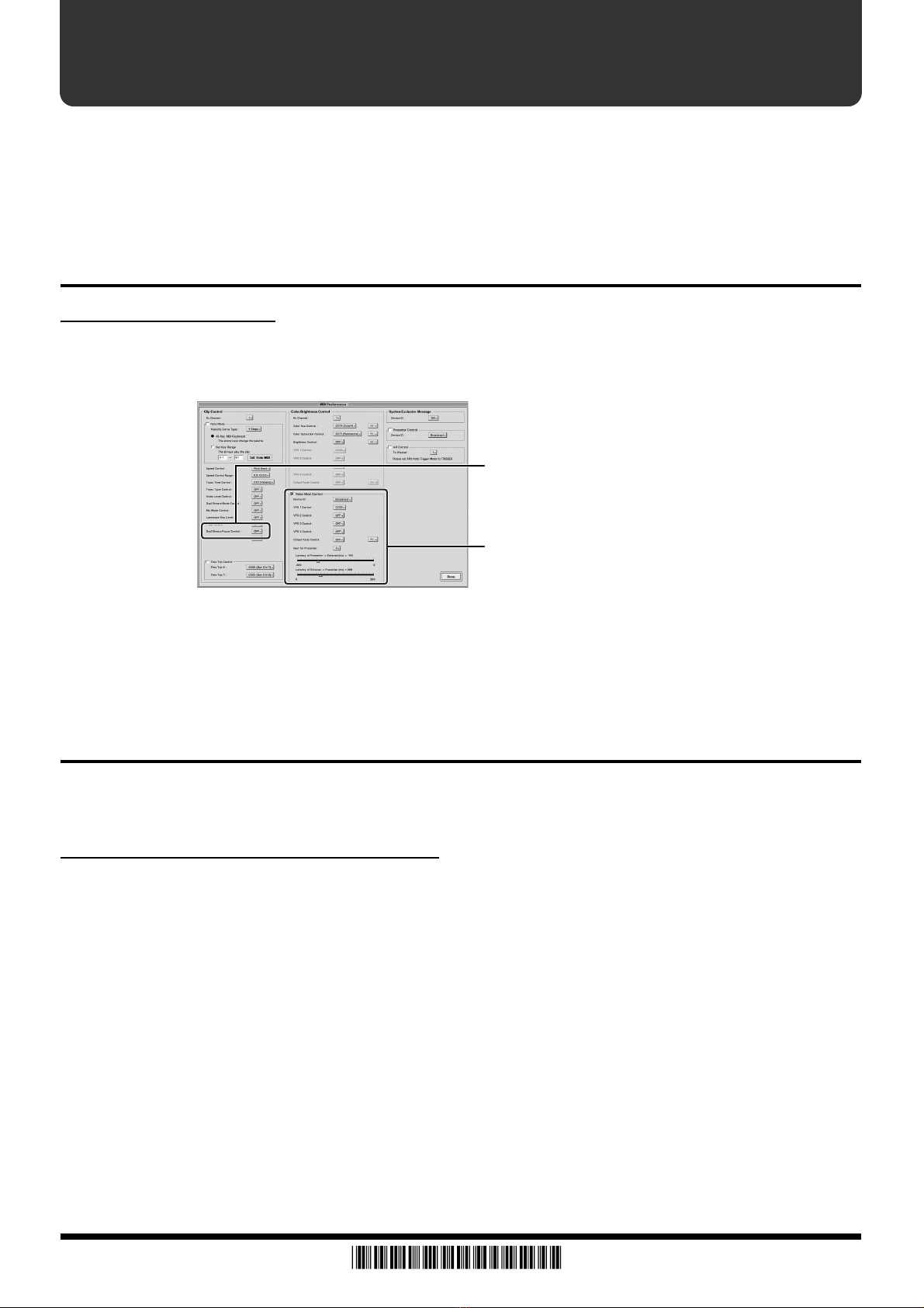
Because the items "Dual Stream Focus" and "Video Mixer Control" have been added to the MIDI
System Settings (p. 88 in the PR-80 Owner's Manual), the screen layout and the names of some items
have changed.
Dual Stream Focus
This lets you select the stream that selects the clip in the Dual Stream mode. If you're manipulating
this control via MIDI, go to "Dual Stream Focus" and set the MIDI message to be used. (Controls are
not accepted via MIDI when this is set to [OFF].)
The stream for the Dual Stream mode is selected using the chosen MIDI message.
Using Other Devices to Control Presenter
The feature known as "V-4 Control" in previous versions is now called "Video Mixer Control" and
also supports other video mixers in addition to the V-4. Along with this, some other features have
been added or changed.
Controlling an Edirol Video Mixer
Using a video mixer from Edirol (such as the V-4 or V-440HD) in combination with the PR-80 lets you
control the video mixer using the PR-80. When you do this, you can take the video input to the video
mixer from the external source and work with it as clips using the PR-80. Additionally, you can use
an external MIDI device to control the video mixer's effect settings and fade the final video output.
1.
Using MIDI cables, connect a USB MIDI interface to the PR-80 and connect the MIDI
interface's MIDI OUT to the video mixer's MIDI IN.
For more information about USB MIDI interfaces, refer to p. 88.
2.
Input the video output from the PR-80 to the video mixer.
3.
Turn on the power to the PR-80 and the video mixer.
When you're making the connection, first turn on the power to the video mixer, then turn on the
PR-80.
4.
Set the Device ID for the video mixer.
For instructions on how to set the Device ID, refer to the owner's manual that came with the video
mixer.
Video Mixer Control
Dual Stream Focus
*40678612-01*
PR-80 40678612 1REC
5.
If you're in the Play mode, click the [Preferences] button and then the [MIDI Preferences]
button. If you're in the Edit mode, click the [Preferences] button.
6.
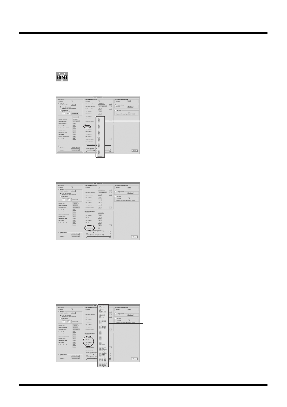
Use "Device ID" to set the Device ID for "Video Mixer Control."
Select the same Device ID as the one you set for the video mixer in Step 4.
When set to Broadcast, control messages can be transmitted regardless of the setting for the video
mixer.
7.
Use "Presenter Connection Input" to set the input channel on the video mixer used to input
PR-80 video in Step 2.
8.
Go to "Video Mixer Control" and use "VFX1 Control" to set the MIDI message that controls the
video mixer's effects.
(Controls are not accepted via MIDI when this is set to [OFF].)
The effects are controlled with the selected MIDI message.
A MIDI value of 0 corresponds to "OFF," and values 1 through 127 correspond to "ON" (or to changes
in the parameter if the effect has variable parameters). Set "VFX2 Control" through "VFX4 Control" in
the same way.
Some video mixers may not support this feature.
This setting is shared with “Controlling Effects” (p. 95).
Select a Device ID
Select a MIDI message
9.
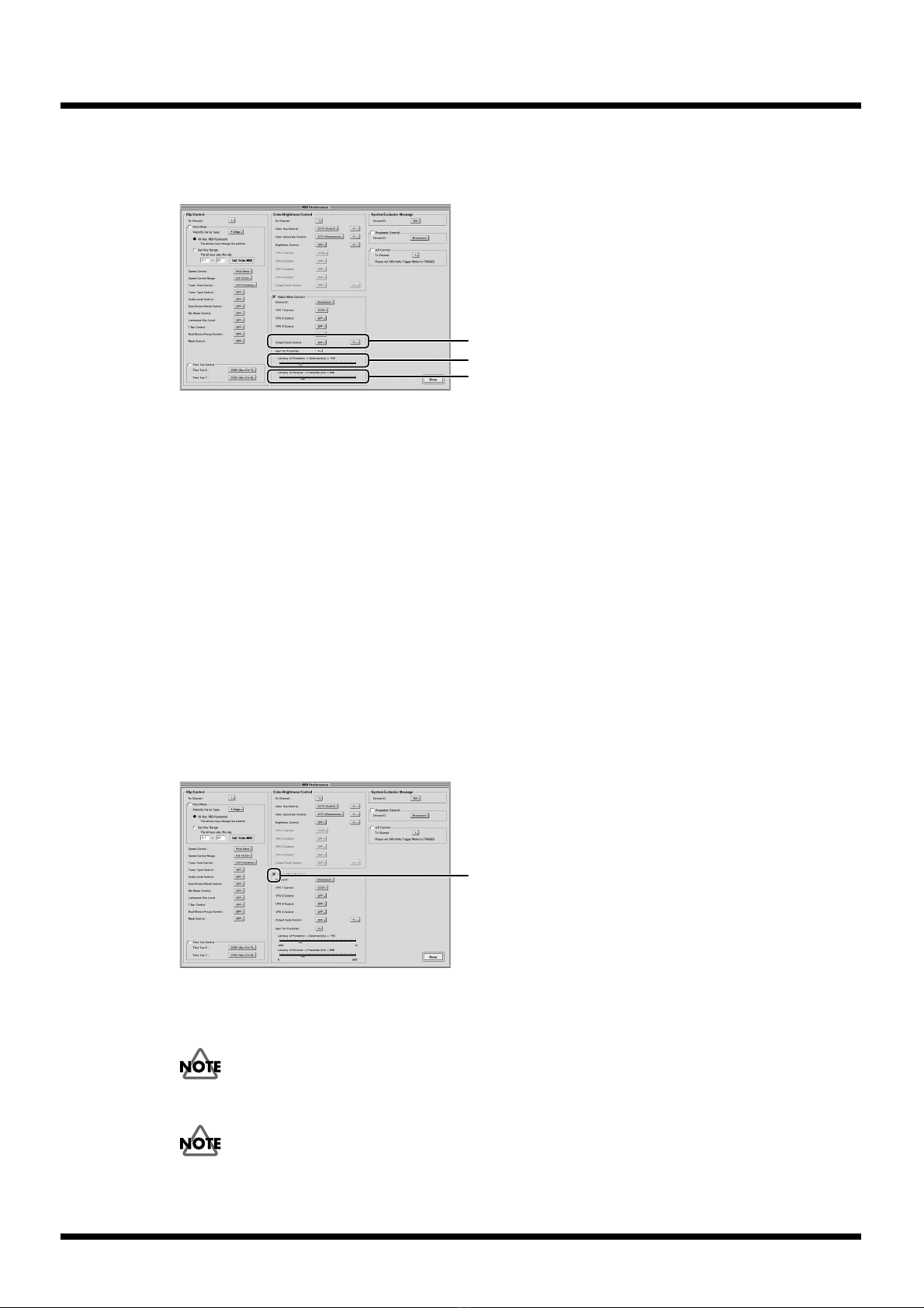
Go to "Color/Brightness Control" and use "Output Fade" to select the MIDI message that
controls the fade applied to the video mixer's final video output.
(Controls are not accepted via MIDI when this is set to [OFF].)
The fade applied to the video mixer's final video output is controlled by the selected MIDI message.
The range of MIDI values, 0–64–127, corresponds to the range of the minimum to maximum values
for the parameter.
You can use the box on the right side to select the polarity of the control. Select "+" to set the parameter
targeted for MIDI control to [0: normal playback – 64: 50% white fade – 127: 100% white fade], "-" for
[127: 100% black fade – 64: 50% black fade – 0: normal playback], and "+/-" for [-127: 100% black fade
– 0: normal playback – 127: 100% white fade].
Some video mixers may not support this feature.
This setting is shared with “Controlling Fades” (p. 94).
10.
To set the latency between the PR-80 and the video mixer, use the "Presenter => External
Latency" and "External => Presenter Latency" settings.
The latency (delay) for operations made from the PR-80 may differ from one video mixer to another.
If video transitions under control from the PR-80 are corrupt, or if unexpected video is seen during
such transitions, then adjust these two values to make video transitions smooth. Delay can also be
applied to input switching on the video mixer, so adjusting this may also be a good idea.
(For information on the V-4 and the V-440HD, refer to “Setting Examples for Edirol Video Mixers”.)
11.
Select the "Video Mixer Control" check box.
This enables the Video Mixer Control feature.
12.
Click the [Done] button.
For more details about operating the video mixer, refer to the owner's manual that came with the
video mixer.
Presenter's output-fade and effects cannot be controlled with MIDI while the Video Mixer Control
feature is on.
If you find the controls are not working well, try turning off the control feature (clearing the check
box) and turning it on again (selecting the check box once more).
Set "Output Fade"
Set "Presenter => External Latency"
Set "External => Presenter Latency"
Mark the checkbox
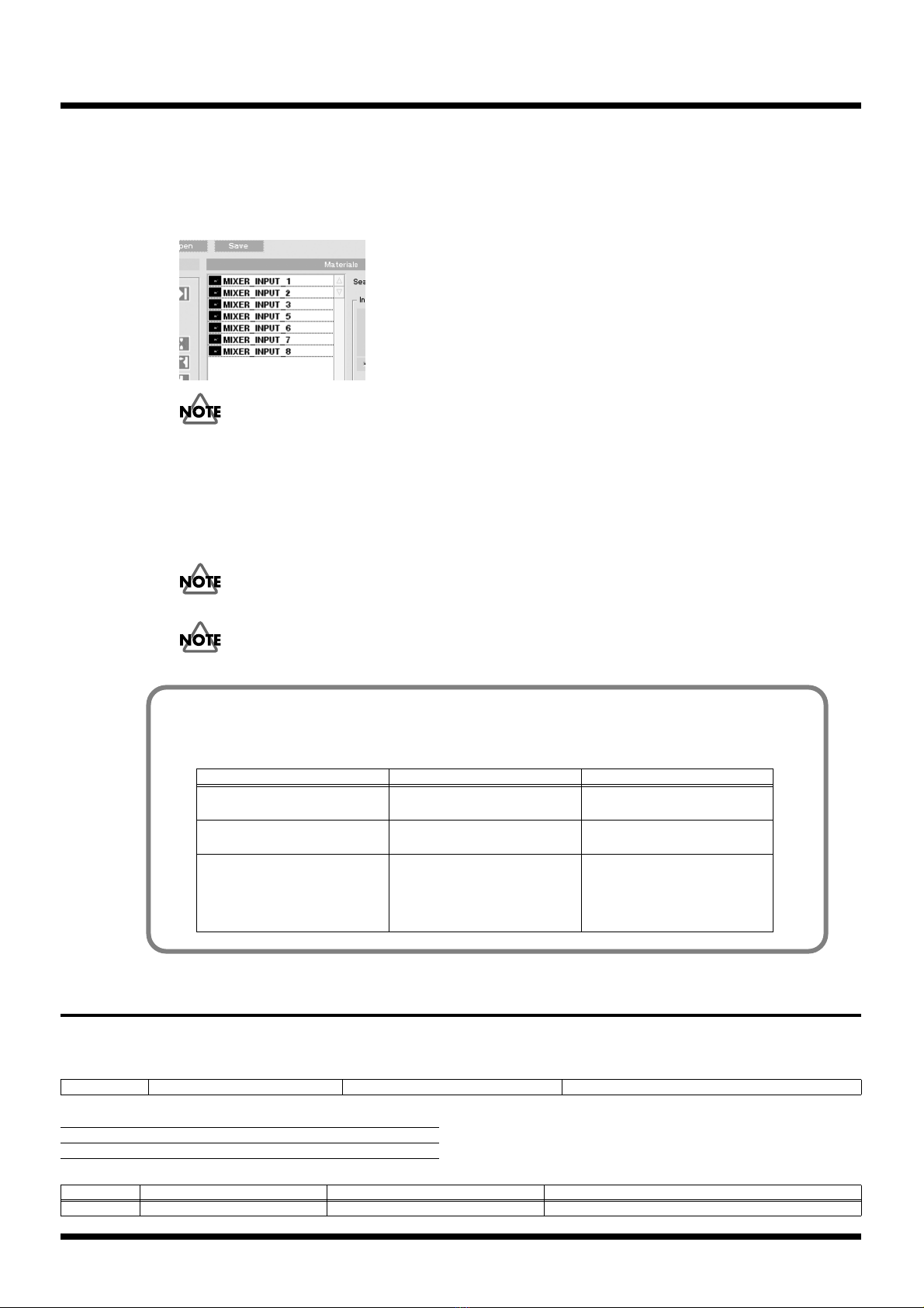
13.
Input from the video mixer appears on the "Material" list with a name like "MIXER INPUT 1."
You can assign input from the video mixer to a clip by dragging material having such names
to the "Clips" list.
"MIXER INPUT" data items from 1 through 8 are displayed. The video-mixer input you set in Step 10
is not displayed.
When you are connecting to the PR-80 a video mixer that has fewer than eight inputs, such as the V-
4, never drag to the "Clips" list a "MIXER INPUT" item whose number exceeds the number of input
channels on the video mixer.
When a clip has been created by dragging a "MIXER INPUT" item whose number exceeds the number
of input channels on the video mixer to the "Clips" list, selecting the clip while in the Play mode may
cause the words "MIXER INPUT" to appear in the output video or result in a failure to switch the
input channel.
In the Play mode, never rapidly switch clips created by dragging "MIXER INPUT" to the "Clips" list.
When you're using Video Mixer Control, never try to operate the video mixer directly.
MIDI implementation (Presenter)
3.Parameter address map
3-1-1. Clip Control Preference Area
3-2. V-LINK (Model ID = 00H 51H)
3-2-2. Clip Control Assignment Area
#10H 10H 16H Dual Stream Focus Control Assignment 01H-05H, 07H-1FH, 40H-5FH, D0H, E0H, FFH Control Change, Channel Press, Pitch Bend, OFF
Parameter Assigned Value
Dual Stream Focus OFF -
Address Parameter Name Sys.Ex.Value Meaning of Value
#10H 10H 26H V-LINK Rx Setting (Dual Stream Focus) 01H-05H, 07H-1FH, 40H-5FH, D0H, E0H, FFH Dual Stream Focus : Control Change, Channel Press, Pitch Bend, OFF
Setting Examples for Edirol Video Mixers
When you have connected an Edirol video mixer, using settings for the "Video Mixer Control" items
like the ones in the examples shown below may be useful.
V-4 V-440HD
Presenter =>
External Latency
-150 -80
External =>
Presenter Latency
60 70
Additional tips Set the memory 8 MIX button
on the V-4 to Mix01. Also, when
performing control from a PR-
80, flip the video fader to the A
channel.
Of "MIXER INPUT" items
1 – 8, 1 – 4 correspond to SD in-
put and 5–8 correspond to HD/
RGB input.
Copyright © 2006 ROLAND CORPORATION
All rights reserved. No part of this publication may be reproduced in any form without the written permission of ROLAND CORPORATION.
Table of contents
Other Roland Digital Presenter manuals

Popular Digital Presenter manuals by other brands


Samsung
Samsung SDP-850 user manual

Dukane
Dukane DV-P303A Specifications

RemotePoint
RemotePoint Presenter Global user manual

Kensington
Kensington Wireless Presenter with Laser Pointer Operating instruction guide

NEC
NEC DS1-MP10RX2 Important information

Logitech
Logitech R800 - Professional Presenter Presentation Remote... quick start guide