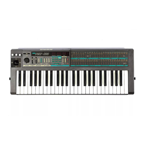
Roland Juno-GJ Operating and maintenance manual

SERVICE NOTES
Issued by RJA
Copyright © 2006 ROLAND CORPORATION
All rights reserved. No part of this publication may be reproduced in any form without the written permission
of ROLAND CORPORATION.
Printed in Japan (0500) (SC-KWS)17058414E0
Apr. 2006 JUNO-G/JUNO-G (J)
Table of Contents
Cautionary Notes ..............................................................2
Specifications .....................................................................2
Location of Controls/Location of Controls Parts List .4
Exploded View (1).............................................................6
Exploded View (1) Parts List...........................................7
Exploded View (2).............................................................8
Exploded View (2) Parts List...........................................9
Keyboard Parts List.........................................................10
Parts List ...........................................................................11
Wiring Diagram...............................................................14
Checking Version Number ............................................15
Data Save (User Backup)................................................15
Data Load (User Restore)...............................................16
Factory Reset....................................................................16
System Update.................................................................16
Test Mode.........................................................................17
Block Diagram .................................................................23
Circuit Board (MAIN Board: 1/2).................................24
Circuit Board (MAIN Board: 2/2).................................25
Circuit Board (JACK, PANEL-C, LCD Board: 1/2)....26
Circuit Board (JACK, PANEL-C, LCD Board: 2/2)....27
Circuit Board (PANEL-A, B Board)..............................28
Circuit Diagram (MAIN Board: 1/4)............................30
Circuit Diagram (MAIN Board: 2/4)............................32
Circuit Diagram (MAIN Board: 3/4)............................34
Circuit Diagram (MAIN Board: 4/4)............................36
Circuit Diagram (JACK Board: 1/2) .............................38
Circuit Diagram (JACK Board: 2/2) .............................40
Circuit Diagram (PANEL-A Board) .............................42
Circuit Diagram (PANEL-B Board) ..............................44
Circuit Diagram (PANEL-C Board: 1/2) .....................46
Circuit Diagram (PANEL-C Board: 2/2) .....................48
Error Messages ................................................................50

2
Apr. 2006 JUNO-G/JUNO-G (J)
Cautionary Notes
User data status
User data status after each of the following processes is described below.
Whenever carrying out procedures that involve deleting or erasing user data,
always be sure to back up the user data to some form of external storage
media. Refer to Data Save (User Backup) (p. 15).
* Executing Test Mode during Factory Reset deletes the user data.
Parts List
Due to one or more of the following reasons, parts with parts code ********
cannot be supplied as service parts.
• Part supplied only as a component in a complete assembly
• Copyright does not permit the part to be supplied
• Part is sold commercially
Circuit Diagram
In the circuit diagram, ‘NIU’ is an abbreviation for ‘NOT IN USE’.
The circuit board and circuit-board diagram show silkscreened indications, but
no components are mounted.
Specifications
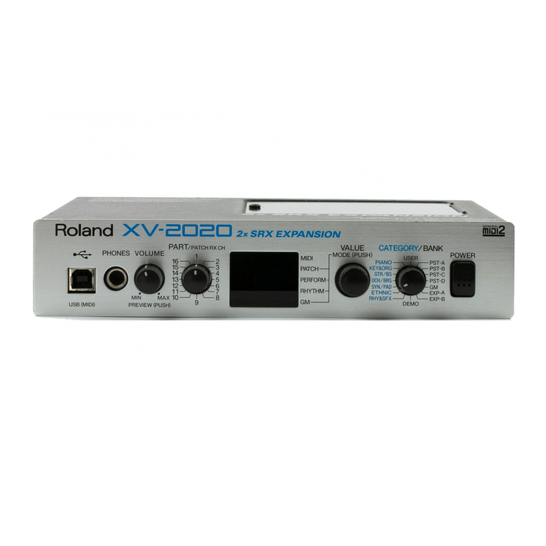
JUNO-G: Synthesizer Keyboard (Conforms to General MIDI 2 System)
Keyboard
61 keys (with velocity)
■Sound Generator Section
Maximum Polyphony
128 voices (shared with audio track section)
Parts
16 parts
Wave Memory
64 M bytes (16-bit linear equivalent)
Preset Memory
Patches: 768 + 256 (GM2)
Rhythm Sets: 36 + 9 (GM2)
Performances: 64
User Memory
Patches: 256
Rhythm Sets: 32
Performances: 64
Effects
Multi-Effects: 3 systems, 78 types
Chorus: 3 types
Reverb: 5 types
Input Effects: 6 types
Mastering Effects: 3-band compressor
■Song Recorder Section
Tracks
MIDI tracks: 16
Audio tracks: 4 stereo tracks
Tempo track: 1
Beat track: 1
Song Length
9998 measures
Tempo
5–300
MIDI Track
Resolution: 480 TPQN
Note Capacity: approx. 400,000 notes
Recording Method: Realtime recording, Step recording
Process User Data
Checking Version number Preserved
Factory Reset Deleted
System Update Deleted
Test Mode Preserved

3
Apr. 2006 JUNO-G/JUNO-G (J)
Audio Track
Data Format: 16-bit linear
Sample Rate: 44.1 kHz
Recording Time:
• memory not expanded (4 M bytes)
approx. mono 47 seconds (stereo 23.5 seconds)
• memory fully expanded (516 M bytes)
approx. mono 102 minutes (stereo 51 minutes)
■Others
Arpeggiator
Preset: 128
User: 128
Rhythm Pattern
Preset: 256 (32 groups)
User: 256 (32 groups)
Chord Memory
Preset: 64
User: 64
Controllers
D Beam Controller
Pitch Bend/Modulation Lever
Sound Modify Knob x 6
Display
240 x 96 dots graphic LCD (with backlit)
Expansion Slots
SRX expansion board: 1 slot
DIMM: 1 slot (memory expansion for audio recording)
External Storage Device
PC Card: 1 slot
(supports SmartMedia and CompactFlash using a PC card adaptor)
Connectors
Headphones Jack
Output Jacks (L (MONO), R): 1/4 inch phone type
Input Jacks (L (MONO)/MIC, R): 1/4 inch phone type
MIDI Connectors (IN, OUT)
Hold Pedal Jack
Control Pedal Jack
USB Connector (supports file transfer and MIDI)
Power Supply
DC 9 V (AC Adaptor)
Current draw
2000 mA
Dimensions
1022.8 (W) x 298.4 (D) x 101.7 (H) mm
40-5/16 (W) x 11-3/4 (D) x 4-1/16 (H) inches
Weight
6.2 kg / 13 lbs 11 oz (excluding AC Adaptor)
Accessories
Owner’s Manual English (#04232578)
CD-ROM (Editor/Librarian/USB MIDI driver) (#04349890)
CD-ROM (SONAR LE) (********)
PC Card Protector (#04124301)
AC Adaptor (#03017356)
AC Cord Set (#02562456 for 117V U and 117V U/CS)
(#01903356 for 230V EU and 230V E)
(#03785590 for 240V A)
Options
Wave Expansion Board: SRX Series
Keyboard Stand: KS-12
Pedal Switch: DP series
Foot Switch: BOSS FS-5U
Expression Pedal: EV-5

Apr. 2006 JUNO-G/JUNO-G (J)
Location of Controls/Location of Controls Parts List
fig.top-panel@L
fig.rear-panel@L
No. Parts Code Parts Name Description Q'ty
101343089 ESCUTCHEON D-BEAM CONTROLLER ESCT BLK 1
2 03126134 LED (INFRARED) TLN233 (F) 1
3 01900612 DIODE TPS611(F) 1
4 02891789 TACT SWITCH SKRGADD010 H=5.0 1
4 04348801 D S-KEYTOP SX1H-B GRS 1
4 03893601 LED SLR343BCT3F 1
5 01904112 LED (RED) SLR-342VCT32 N.P.Q RANK 25
5 02891789 TACT SWITCH SKRGADD010 H=5.0 25
5 04348801 D S-KEYTOP SX1H-B GRS 25
6 01904112 LED (RED) SLR-342VCT32 N.P.Q RANK 10
6 02891789 TACT SWITCH SKRGADD010 H=5.0 10
6 04124312 N S-KEYTOP MD1H BLK MNP 10
7 04010634 LCD 1
7 04128778 DISPLAY COVER 1
8 03122134 ROTARY ENCODER EC12E2420802 1
8 04128090 D R-KNOB L-ELA MNP 1
9 02891789 TACT SWITCH SKRGADD010 H=5.0 13
9 04348801 D S-KEYTOP SX1H-B GRS 13
10 01239867 LED (RED/GREEN) CLR SML72423C TP15 1
10 02891789 TACT SWITCH SKRGADD010 H=5.0 1
10 04348801 D S-KEYTOP SX1H-B GRS 1
11 02454278 LED SLR-322MC-T32 1
11 02891789 TACT SWITCH SKRGADD010 H=5.0 1
11 04348801 D S-KEYTOP SX1H-B GRS 1
12 04124278 S-KNOB SLV 5
12 04233478 SLIDE POTENTIOMETER 30M/M RS30111AC019 5
2 4 7 851 316 129 14
5 10 13
65
1115
17 1918 20
5 9
21 22 23 25 26 27 28
24 29
54
No. Parts Code Parts Name Description Q’ty
13 00899023 LED LNJ282RKRXE 3
14 02455223 9M/M ROTARY POTENTIOMETER EVUF2KFK4B14 6
14 04124267 J R-KNOB SF-ELA BLK/SLV 6
15 02455234 12M/M ROTARY POTENTIOMETER EVJY15F02B14 1
15 04124267 J R-KNOB SF-ELA BLK/SLV 1
16 04122867 TOP PANEL 1
17 04124223 SIDE PANEL L 1
18 03234723 BENDER PB-H0204 1
19 04344189 KEYBOARD ASSY MSK-2 61KEY (W/O CABLE) 1
20 04124234 SIDE PANEL R 1
21 04128767 POTENTIOMETER RK09K1110AFG 1
22 02781189 USB CONNECTOR B TYPE FEMALE YKF45-0021 1
23 01343545 CONNECTOR SCAA1A0900 1
23 02900867 CARD EJECTOR SCAB1A5600 1
23 04124290 PC CARD ESCUTCHEON BLK MNP 1
24 13429825 MIDI CONNECTOR YKF51-5054V 2
25 02781390 9M/M ROTARY POTENTIOMETER RK09K12A0D0S 20KAX2 1
26 04451556 CORD HOOK MNP 1
27 13449711 AC ADAPTOR JACK HEC0470-01-630 (for JUNO-G (J)) * equivalent to #13449720 1
27 13449720 DC JACK HEC2305-01-250 (for JUNO-G) * equivalent to #13449711 1
28 01676512 PUSH SWITCH SDKLA10200 1
28 12499175 BUTTON JSPUE0011A 1
29 00569278 6.5MM JACK LGR4609-7000 9

6
Apr. 2006 JUNO-G/JUNO-G (J)
Exploded View (1)
fig.bunkai
View 3
19
18
16
17
23 24
21
22
26
27
30
29
28
33
32
31
15
46
7
3
2
13
8
33
1
5
9
10
11
20 14
View 1
View 2
Rear
Bottom
21
22
12
25

7
Apr. 2006 JUNO-G/JUNO-G (J)
Exploded View (1) Parts List
No. Parts Code Parts Name Description Q'ty
1 04124267 J R-KNOB SF-ELA BLK/SLV 1
2 01676512 PUSH SWITCH SDKLA10200 1
3 04451556 CORD HOOK MNP 1
4 04128090 D R-KNOB L-ELA MNP 1
5 04124278 S-KNOB SLV 5
6 04124301 PROTECTOR PC CARD 1
7 04124267 J R-KNOB SF-ELA BLK/SLV 6
8 04122867 TOP PANEL 1
9 04124223 SIDE PANEL L 1
10 04128778 DISPLAY COVER 1
11 04010634 LCD 1
12 04124256 LCD HOLDER 2
13 04124234 SIDE PANEL R 1
14 04231889 PANEL-A BOARD ASSY 1
15 04235178 INSULATING SHEET FOR PANEL-A BOARD 1
16 04231890 PANEL-B BOARD ASSY 1
17 04235189 INSULATING SHEET FOR PANEL-B BOARD 1
18 73342067 PANEL-C BOARD ASSY JAPAN equivalent to #04231923 1
19 04235190 INSULATING SHEET FOR PANEL-C BOARD 1
20 03234723 BENDER PB-H0204 1
21 03671278 METAL HOLDER FOR SIDE PANEL 2
22 04124334 PWB HOLDER 5
23 73342078 LCD BOARD ASSY 1
24 00673067 PWB SPACER WLS-04-0 4
25 04344189 KEYBOARD ASSY MSK-2 61KEY (W/O CABLE) 1
25 04344201 CABLE ASSY FOR MSK-2 1
26 04124323 PANEL HOLDER 3
27 73342089 JACK BOARD ASSY JAPAN equivalent to #04231934 1
28 73342090 MAIN BOARD ASSY JAPAN equivalent to #04231867 1
29 03671290 REINFORCE BAR 1
30 04129323 SHIELD SHEET 1
31 04124212 BOTTOM CASE 1
32 04124245 EXPANSION COVER 1
33 12359137 RUBBER FOOT SJ-5012 BLK 4

8
Apr. 2006 JUNO-G/JUNO-G (J)
Exploded View (2)
fig.heimen
e
e
View 2
View 3
View 1
e
b
b
e
e
b
b
a
e

9
Apr. 2006 JUNO-G/JUNO-G (J)
fig.heimen
Exploded View (2) Parts List
Rear
Bottom
d
c
b
a
f
a
a
h
gg
No. Parts Code Parts Name Description Q'ty
a 40012956 SCREW M3X8 PAN MACHINE W/SW+PW FE BZC 16
b 40011312 SCREW 3X8 BINDING TAPTITE P BZC 14
c 40340812 SCREW M3X10 PAN MACHINE W/SW BZC 1
d 40454856 SCREW M4X10 BINDING NI 1
e 40011101 SCREW 3X8 BINDING TAPTITE B BZC 35
f 40011334 SCREW 3X12 BINDING TAPTITE-P FE BZC 12
g 40012501 SCREW M4X12 BINDING TAPTITE P FE BZC 5
h 40011123 SCREW 4X8 BINDING TAPTITE B BZC 5

10
Apr. 2006 JUNO-G/JUNO-G (J)
Keyboard Parts List
fig.keys
10
2
6
7 118
4
5
1 3
9 a
No. Part Code Part Name Description Q'ty
1 03786378 NATURAL KEY C FOR MSK-2 5
1 03786389 NATURAL KEY D FOR MSK-2 5
1 03786390 NATURAL KEY E FOR MSK-2 5
1 03786401 NATURAL KEY F FOR MSK-2 5
1 03786412 NATURAL KEY G FOR MSK-2 5
1 03786423 NATURAL KEY A FOR MSK-2 5
1 03786434 NATURAL KEY B FOR MSK-2 5
1 03786445 NATURAL KEY C’ FOR MSK-2 1
2 03786456 SHARP KEY FOR MSK-2 25
3 03786312 KEY FELT MSK-2 HOOK T2.0MM L828XW5.5 1
4 03456967 COILED SPRING MSK-1 NATURAL KEY 36
4 03456978 COILED SPRING MSK-1 SHARP KEY 25
5 03786301 KEY FELT MSK-2 BACK T4.0MM L840XW6.0 1
6 03456856 RUBBER SW KEYBOARD 12P FOR MSK-1 4
6 03456867 RUBBER SW KEYBOARD 13P FOR MSK-1 1
7 03786345 PWB KEYBOARD LO ASSY FOR MSK-2 1
7 03786356 PWB KEYBOARD HI ASSY FOR MSK-2 1
8 ******** CHASSIS KEYBOARD FOR MSK-2 1
9 03786334 KEY FELT MSK-2 BOTTOM M T2.0MM L840XW10 1
10 03786323 KEY FELT MSK-2 BOTTOM L T2.0MM L840XW15 1
11 15019126 SWITCHING DIODE 1SS133 T-77 122
a 40011189 SCREW 3X8 PAN TAPTITE-P FE ZC 34

11
Apr. 2006 JUNO-G/JUNO-G (J)
Parts List
CASING
01343089 ESCUTCHEON D-BEAM CONTROLLER ESCT
BLK
1
# 04124290 PC CARD ESCUTCHEON BLK MNP 1
# 04124212 BOTTOM CASE 1
# 04128778 DISPLAY COVER 1
# 04124245 EXPANSION COVER 1
# 04124223 SIDE PANEL L 1
# 04124234 SIDE PANEL R 1
# 04122867 TOP PANEL 1
CHASSIS
03671278 METAL HOLDER FOR SIDE PANEL 2
# 04124256 LCD HOLDER 2
# 04124323 PANEL HOLDER 3
# 04124334 PWB HOLDER 5
03671290 REINFORCE BAR 1
KNOB, BUTTON
# 04348801 D S-KEYTOP SX2H-B GRS MNP 9
# 04124278 S-KNOB SLV 5
04124267 J R-KNOB SF-ELA BLK/SLV 6
# 04124312 N S-KEYTOP MD1H BLK MNP 1
# 04128090 D R-KNOB L-ELA MNP 1
12499175 BUTTON JSPUE0011A 1
SWITCH
02891789 TACT SWITCH SKRGADD010 H=5.0 1
01676512 PUSH SWITCH SDKLA10200 1
JACK, EXT TERMINAL
13429825 MIDI CONNECTOR YKF51-5054V 1
02781189 USB CONNECTOR B TYPE FE-
MALE
YKF45-0021 1
02900867 CARD EJECTOR SCAB1A5600 1
01343545 CONNECTOR SCAA1A0900 1
00569278 6.5MM JACK LGR4609-7100F 1
13449711 AC ADAPTOR JACK HEC0470-01-630 for JUNO-G (J) (equivalent to #13449720) 1
13449720 DC IN JACK HEC2305-01-250 for JUNO-G (equivalent to #13449711) 1
DISPLAY UNIT
# 04010634 LCD 1
BENDER UNIT
03234723 BENDER PB-H0204 1
KEYBOARD ASSY
# 04344189 KEYBOARD ASSY MSK-2 61KEY (W/O CABLE) 1
# 04344201 CABLE ASSY FOR MSK-2 FOR KEYBOARD ASSY 1
* KEYBOARD ASSY and CABLE ASSY need to be ordered separately.
PWB ASSY
# 73342078 LCD BOARD ASSY 1
# 73342089 JACK BOARD ASSY JAPAN equivalent to #04231934 1
# 73342090 MAIN BOARD ASSY JAPAN equivalent to #04231867 1
# 04231889 PANEL-A BOARD ASSY 1
# 04231890 PANEL-B BOARD ASSY 1
# 73342067 PANEL-C BOARD ASSY JAPAN equivalent to #04231923 1
DIODE
01900612 DIODE TPS611(F) 1
03126134 LED(INFRARED) TLN233(F) 1
01239867 LED (RED/GREEN)CLR SML72423C TP15 1
03893601 LED SLR343BCT3F 1
01904112 LED(RED) SLR-342VCT32 N.P.Q RANK 1
02454278 LED SLR-322MC-T32 1
00899023 LED LNJ282RKRXE 1

12
Apr. 2006 JUNO-G/JUNO-G (J)
15019126 SWITCHING DIODE 1SS133 T-77 D1, D2, D3, D4, D5, D6, D7, D8, D9, D10,
D11, D12, D13, D14, D15, D16, D17, D18,
D19, D20, D21, D22, D23, D24, D25, D26,
D27 on PANEL-A
D28, D29, D30, D31, D32, D33, D34, D35,
D36, D37, D38, D39 on PANEL-B
39
DIODE
POTENTIOMETER
02781390 9M/M ROTARY POTENTIOM-
ETER
RK09K12A0D0S 20KAX2 1
# 04128767 POTENTIOMETER RK09K1110AFG 1
02455223 9M/M ROTARY POTENTIOM-
ETER
EVUF2KFK4B14 1
02455234 12M/M ROTARY POTENTI-
OMETER
EVJY15F02B14 1
# 04233478 SLIDE POTENTIOMETER 30M/M RS30111AC019 1
ENCODER
03122134 ROTARY ENCODER EC12E2420802 1
CONNECTOR
02010078 CONNECTOR TX25-80P-6ST-E1 for CN10 on MAIN 1
13369668 CONNECTOR S8B-PH-K-S JST(LF/SN)(8P) for CN2 on PANEL-A and CN13 on PAN-
EL-C
2
13369666 CONNECTOR S6B PH-K-S(LF/SN)(6P) for CN5 on PANEL-A 1
13369664 CONNECTOR S4B-PH-K-S(LF/SN)(4P) for CN15 on PANEL-C 1
# 04126190 CONNECTOR PS-26PE-D4T1-B1E for CN6 on JACK 1
03340289 CONNECTOR B8B-PH-K-S (PB FREE) for CN4 on MAIN and CN3 on JACK 2
13369566 CONNECTOR B6B-PH-K-S JST(LF)(SN)(6P) for CN2 on JACK 1
13369564 CONNECTOR B12B-PH-K-S JST(LF)(SN) for CN11 on MAIN and CN1 on JACK 2
02458456 CONNECTOR 30FE-ST-VK-N for CN3 on PANEL-B and CN12 on PANEL-
C
2
02122467 CONNECTOR 24FE-ST-VK-N for CN1 on PANEL-A and CN4 on PANEL-
B
2
02780734 CONNECTOR 18FMN-STK for CN14 on PANEL-C and CN16, 17 on
LCD
3
02011956 CONNECTOR 18FMN-BTK for CN12 on MAIN and CN4 on JACK 2
02235467 CONNECTOR 14FMN-STK for CN7 on PANEL-C 1
02011912 CONNECTOR 14FMN-BTK for CN13 on MAIN 1
13369826 HEADER CONNECTOR PS-26PE-D4T1-B1-K for CN6 on JACK
WIRING, CABLE
# 04344201 CABLE ASSY FOR MSK-2 for KEYBOARD ASSY 1
# 04232501 BAN CARD BNCD-P=1.25-K-30-170 1
# 04232490 BAN CARD BNCD-P=1.25-K-24-150 1
# 04232456 BAN CARD BNCD-P=1.00-K-18-700 1
# 04232489 BAN CARD BNCD-P=1.00-K-18-200 1
# 04232478 BAN CARD BNCD-P=1.00-K-14-500 1
02343645 WIRING 8X650-P2.0-PHR-PHR-F 1
02343623 WIRING 8X550-P2.0-PHR-PHR-F 1
02343234 WIRING 6X150-P2.0-PHR-PHR-F 1
02342167 WIRING 4X900-P2.0-PHR-PHR-F 1
# 04232445 WIRING 12X900-P2.0-PHR-PHR-F 1
SCREWS
40343367 SCREW M2X14 PAN MACHINE W/
SW+SMALL PWZC
1
40012956 SCREW M3X8 PAN MACHINE W/SW+PW FE
BZC
16
40340812 SCREW M3X10 PAN MACHINE W/SW BZC 1
40011501 SCREW M3X8 PAN MACHINE W/SW BZC 1
40011334 SCREW 3X12 BINDING TAPTITE-P FE BZC 12
40011312 SCREW 3X8 BINDING TAPTITE P BZC 14
40011101 SCREW 3X8 BINDING TAPTITE B BZC 35
40011123 SCREW 4X8 BINDING TAPTITE B BZC 1
40454856 SCREW M4X10 BINDING NI 1
40011189 SCREW 3X8 PAN TAPTITE-P FE ZC for Bender Unit 3
40012501 SCREW M4X12 BINDING TAPTITE P FE BZC 5
PACKING
# 04232534 PACKING PAD SIDE R 1
# 04232523 PACKING PAD SIDE L 1
# 04232545 PACKING PAD CENTER 1
# 04232556 PACKING PAD ADAPTOR 1
# 04232512 PACKING CASE 1

13
Apr. 2006 JUNO-G/JUNO-G (J)
MISCELLANEOUS
00673067 PWB SPACER WLS-04-0 1
40016534 INSULOK TIE 204M/M T-18L 1
12359137 RUBBER FOOT SJ-5012 BLK 1
01902756 PWB SPACER RSPS-12L 1
02019034 PWB SPACER RSPLS-12L 1
40122812 ACETATE TAPE NITTO NO.5 BLK W15MM 30M 1
12199584 GROUNDING TERMINAL M1698 1
02230578 LED SPACER LDS-50R 1
12169368 LED SPACER LDS-40B 1
# 04235190 INSULATING SHEET FOR PANEL-C BOARD 1
# 04235189 INSULATING SHEET FOR PANEL-B BOARD 1
# 04235178 INSULATING SHEET FOR PANEL-A BOARD 1
40120967 COATING CLIP CS-3 6
# 04236390 LCD CUSHION 400MM 1
# 04450089 HEATSINK PC1115-25-PB-SN for JUNO-G (J) (equivalent to #04236412) 1
# 04236412 HEATSINK 25X15X11 for JUNO-G (equivalent to #04450089) 1
# 04236378 CUSHION 20X30X40 1
40122556 DOUBLE FACED ADHESHIVE
TAPE
#575X W30MM 30M 10P 30CM 1
40122901 DOUBLE-FACED TAPE #501F W10MM 20M 20P (CM) 1
04451556 CORD HOOK MNP 1
01343090 LED SPACER 1
# 04124301 PROTECTOR PC CARD 1
# 04129323 SHIELD SHEET 1
ACCESSORIES (Standard)
# 04232567 (HP)OWNER’S MANUAL JAPANESE 1
# 04232578 OWNER’S MANUAL ENGLISH 1
# 40674601 (HP)LEAFLET CONTENTS LIST 1
# 04349890 CD-ROM EDITOR & DRIVER
V1.01
1
03017356 AC ADAPTOR WITHOUT AC
CORD
PSB-1U(R) UNIVERSAL 1
01903334 AC CORD SET PSE 100V 1.0M FOR PSB-1U for 100V 1
02562456 AC CORD SET 120V 1.0M (NON POLAR) for 117V U, 117V U/C 1
01903356 AC CORD SET 230V 1.0M FOR PSB for 230V EU, 230V E 1
00905234 EURO CONVERTER PLUG ECP01-5A for 230V E 1
03785590 AC CORD SET SC-078-NA05 240VA for 240V A 1
40232334 WARRANTY CARD MOCHIKOMI JAPAN ONLY 1

14
Apr. 2006 JUNO-G/JUNO-G (J)
Wiring Diagram
fig.wiring_85
CN5 (Audio)
6pin 2.0mm PHR
CN2 (Audio)
6pin 2.0mm PHR
CN6 (Keyboard)
26pin 1.25mm Flat
CN1 (Audio)
12pin 2.0mm PHR
CN3 (Power)
8pin 2.0mm PHR
CN4 (Power)
8pin 2.0mm PHR
CN4 (Serial and etc)
18pin 1.0mm FPC
CN13 (D-BEAM)
8pin 2.0mm PHR
CN2 (D-BEAM)
8pin 2.0mm PHR
CN7 (serial)
14pin 1.0mm FPC
CN14 (Serial and etc)
18pin 1.0mm FPC
CN12 (SW & LED)
30pin 1.25mm FPC
CN15 (Bender)
4pin 2.0 PHR
CN4 (SW & LED)
24pin 1.25mm FPC
CN1 (SW & LED)
24pin 1.25mm FPC
CN3 (SW & LED)
30pin 1.25mm FPC
CN11 (Audio)
12pin 2.0mm PHR
CN12 (LCD)
18pin 1.0mm FPC
CN17 (LCD)
18pin 1.0mm FPC
CN13 (serial)
14pin 1.0mm FPC
1
3
6
8
75
9
4
11
210
Panel A Board
Panel B BoardPanel C Board
Jack Board
Main Board
LCD Board
Bender
MKS-2 Keyboard
No. Parts Code Parts Name Description
1 02343234 WIRING 6X150-P2.0-PHR-PHR-F
2 02343645 WIRING 8X650-P2.0-PHR-PHR-F
3 # 04232445 WIRING 12X900-P2.0-PHR-PHR-F
4 02343623 WIRING 8X550-P2.0-PHR-PHR-F
5 02342167 WIRING 4X900-P2.0-PHR-PHR-F
6 # 04232489 BAN CARD BNCD-P=1.00-K-18-200
7 # 04232478 BAN CARD BNCD-P=1.00-K-14-500
8 # 04232456 BAN CARD BNCD-P=1.00-K-18-700
9 # 04232501 BAN CARD BNCD-P=1.25-K-30-170
10 # 04232490 BAN CARD BNCD-P=1.25-K-24-150
11 # 04344201 CABLE ASSY FOR MSK-2

15
Apr. 2006 JUNO-G/JUNO-G (J)
Checking Version Number
1. Turn on the power of the JUNO-G.
2. Press the [MENU] button in EDIT section on the top panel.
3. Press [ ] [ ] to select 2. System, and press [ENTER].
System Menu appears.
fig.00
4. Press [F6 (INFORMATION)].
SYSTEM INFO appears.
fig.01
5. Press [F3 (VERSION)] to confirm the System Program version.
fig.02
6. After confirming, press [EXIT] to return to PATCH PLAY screen.
Data Save (User Backup)
Saves all of user data in the User Area to a memory card. User data which are
saved by this procedure are as follows.
• Performances
• Patches
• Rhythm Sets
• Rhythm Patterns
• Rhythm Groups
• Arpeggio Styles
• Songs
• Samples
• Chord Forms
• System Settings
* When executing User Backup, about 16 MB as the maximum free space is
necessary in the memory card.
1. Insert a memory card into the slot.
2. Press [MENU] in EDIT to open Top Menu.
3. Press [ ] [ ] to select 3. Utility], and press [ENTER].
UTILITY MENU appears.
fig.03
4. Press [F1 (BACKUP)].
Confirming message appears.
fig.04
5. Press [F6 (EXEC)] to execute the backup.
6. Press [EXIT] to return to PATCH PLAY screen.
Function Buttons
Six buttons of [KBD/ORG]--[VOCAL/PAD] standing in the bottom of
the screen work as buttons (Function Buttons) to select various functions.
They are written like [F1]--[F6] in this document.

16
Apr. 2006 JUNO-G/JUNO-G (J)
Data Load (User Restore)
Restores the user data which have been saved in the memory card with the
User Backup to User Area in JUNO-G.
* All of contents in User Area will be erased after executing User Restore.
1. Insert the memory card in which user data have been saved.
2. Press [MENU] in EDIT to open Top Menu.
3. Press [ ] [ ] to select 3. Utility, and press [ENTER].
UTILITY MENU appears.
fig.03
4. Press [F2 (RESTORE)].
Confirming message appears.
fig.05
5. Press [F6 (EXEC)] to execute the restore.
6. After the message “Completed. Turn the Power off and on again.”
appears, turn off and on the power of the JUNO-G.
Factory Reset
All data in User Area will be lost after executing Factory Reset. If the data
which should not be lost are left in the JUNO-G, save them in memory card by
User Backup function. Refer to Data Save (User Backup) (p. 15).
Never turn off the power while executing Factory Reset. Contents of memory
may be lost.
1. Press [MENU] in EDIT to open Top Menu.
2. Press [ ] [ ] to select 3. Utility, and press [ENTER].
UTILITY MENU appears.
fig.03
3. Press [F3 (FACTORY)].
Confirming message appears.
fig.06
4. Press [F6 (EXEC)] to execute Factory Reset.
5. After the message “Completed. Turn the Power off and on again.”
appears, turn off and on the power of the JUNO-G.
System Update
Before executing System Update, save data in the User Memory to memory
card by User Backup function. Refer to Data Save (User Backup) (p. 15).
Required Items
• JUNO-G
• UPDATE CD-ROM (#17041856)
• Memory Card x 2 (1 GB or less, for updating and for backup of User
Data)
• PC (with a CD-ROM drive and a memory card reader/writer, OS:
Windows Me/2000/XP)
* Don’t use Macintosh.
Update Procedure
1. Save the data in User Memory to a memory card. Refer to Data Save
(User Backup) (p. 15).
2. Boot up the PC, and insert the UPDATE CD-ROM and a memory card
which is not used in step 1.
3. Format the memory card by the PC.
4. Copy the “Roland” folder with its contents in the UPDATE CD-ROM to
the memory card.
5. Release the connection of the PC and the card reader/writer by device
eject button shown in the taskbar at the lower right of the PC screen.
6. Remove the memory card from the card reader/writer.

17
Apr. 2006 JUNO-G/JUNO-G (J)
7. Insert the memory card to the JUNO-G which power is turned off.
8. Turn on the power of the JUNO-G.
Updating starts automatically.
When message “- Completed!” appears in the screen, updating is
completed.
9. Remove the memory card and turn off and on the power.
Work after Updating
1. After System Update, execute Checking Version Number (p. 15) and
Test Mode (p. 17).
2. Restore the data which were saved in User Memory by step 1in Update
Procedure (p. 16). Refer to Data Load (User Restore) (p. 16).
If You Made a Mistake on
Updating
• Turn off the power of the JUNO-G and operate from the beginning again.
• If the updating still cannot be successful, exchange the MAIN Board.
Test Mode
All data in User Area will be lost after executing Test Mode. If the data which
should be saved are left in the JUNO-G, save them in memory card by User
Backup function. Refer to Data Save (User Backup) (p. 15).
Procedure of JUNO-G Test Mode is different between ver. 1.01 or before and
ver. 1.02 or later. This service notes explains procedure for ver. 1.02 or later.
Check the version (Checking Version Number (p. 15)), and if the version is
1.01 or before, then update to ver. 1.02 or later before executing Test Mode.
(System Update (p. 16))
Required Items
• JUNO-G
• Memory Card (equal or less than 1GB)
• Memory (DIMM: 128--512 MB)
• Wave Expansion Board: SRX series
• Expression Pedal (e. g. EV-5)
• Headphones
• Noise Meter
• PC (with USB connector, OS: Windows Me/2000/XP)
• USB Cable x 1
• MIDI Cable x 1
• Audio Cable x 4 or 6
• Monitor Speaker
• Oscillator
• Oscilloscope
Preparation of Test
1. Turn off the power of JUNO-G.
2. Remove the cover on the bottom and set the memory (DIMM) and the
SRX.
3. Turn on the power of the JUNO-G and execute the Factory Reset.
(Factory Reset (p. 16))
4. After completing the Factory Reset, turn off and on the power of the
JUNO-G.
5. Now, boot up the PC for the test of 14. USB (p. 21).
Entering Test Mode
1. Press [MENU] in EDIT.
2. Press [ ] to select 2. System, and press [ENTER].
System Menu appears.
fig.00
3. Press [F6 (INFORMATION)].
SYSTEM INFO appears.
fig.01
4. Press [SHIFT], [F4 (WORLD)], [F5 (BRASS)] and [ENTER] one by one in
this order.
Test Mode starts.
* If you make a mistake in the order, turn off and on the power of the JUNO-G and
retry from the step 1.
Exiting Test Mode
Turn off the power of the JUNO-G.

18
Apr. 2006 JUNO-G/JUNO-G (J)
Test Items
In Test Mode, there are eighteen test items as follows.
1. Version Check
2. Device
3. DIMM
4. Expansion Board
5. Card
6. Encoder
7. Switch & LED
8. Switch2
9. LCD
10. AD
11. Mute
12. MIDI
13. Sound
14. USB
15. D Beam
16. Keyboard
17. Noise
18. Factory Reset
Selecting Test Items
1. Press [MENU] in EDIT to display Line Test Menu.
2. Select test items by rotating VALUE dial or pressing [INC] [DEC] or [ ]
[].
3. Press [ENTER] to execute the test.
Skipping Test Items
When a test item finishes, basically, the test program advances to the next test
item automatically. When the test is NG, however, the test program will not
advance to the next automatically.
In that case, skip the test item by force with the following operations.
[SHIFT] + [ ]: Moves to the next test item by force.
[SHIFT] + [ ]: Moves to the previous test item by force.
Details for Test Items
1. Version Check
Program version number appears in the screen.
fig.07
Press the [F6] button to advance to the next test item.
2. Device
Checks every device.
The following messages appears in the screen and nine test items are
automatically executed.
fig.08
If the all is OK, the test program advances to the next test item automatically.
If there are any problems, NG indicates that point---the test program will not
advance to the next items automatically.
3. DIMM
Checks sockets of DIMMs and the peripheral circuit.
When entering the DIMM test, the following message appears in the screen
and the DIMM test starts automatically.
fig.09
When the test finishes without problem, the test program advances to the next
items automatically.
4. Expansion Board
Checks sockets of the Expansion Board and the peripheral circuit.
When entering the Expansion Board test, the name of the Expansion Board
which is inserted appears in the screen.
fig.10
After checking the name, press the keys to check whether correct tones in the
Expansion Board sound or not.
After checking the tones, press the [F6] button to advance to the next test item.
(If no key were pressed, when the [F6] button are pressed, the test program
doesn’t advance to the next test item.)
Items in Screen Correspond Devices
FLASH (NOR) IC2
FLASH (NAND) IC25
SD-RAM (MAIN) IC3, IC6
SD-RAM (SMPL) IC41, IC45
SD-RAM (DSP) IC49
WAVE ROM IC67
WX IC43
USBC IC26
SUB-CPU JACK SHEET IC13

19
Apr. 2006 JUNO-G/JUNO-G (J)
5. Card
Checks connectors of the PC card and the peripheral circuit.
When entering the Card test, the following message appears in the screen.
fig.11
Insert the PC card prepared previously to the card slot.
If the test is passed, the following message appears.
fig.12
When removing the PC card, the test program advances to the next test item
automatically.
6. Encoder
When entering the Encoder test, the following message appears in the screen.
fig.13
Rotate the VALUE dial counterclockwise for a while, and confirm the Left: 72
OK message appears in the screen.
Next, rotate the VALUE dial clockwise for a while; the Right: 72 OK message
appears in the screen and the test program advances to the next test item
automatically.
7. Switch1 & LED
Checks the function of switches with LED.
When entering the Switch1 & LED test, the following message appears in the
screen.
fig.14
One of the switches with LED on the top panel lights. When pressing the
switch, the next switch with LED lights. Continue this operation. When the
tests of all switches are passed, the test program advances to the next test item
automatically.
8. Switch2
Checks the function of switches without LED.
When entering the Switch2 test, the following message appears in the screen.
fig.15
Press the switches drawn with solid lines one by one.
Confirm the color of the corresponding switch will be light.
When all switch’s color are light and the test result is OK, the test program
advances to the next test item automatically.
9. LCD
Checks the function of the LCD.
When entering the LCD test, the following message appears in the screen.
fig.16
Display pattern are changed whenever [F6] is pressed, then check whether
dots are chipped, density is uniform, dust exist or not.
Tiles
fig.17
Tiles (reversed)
fig.18

20
Apr. 2006 JUNO-G/JUNO-G (J)
All Over
fig.19
Nothing
fig.20
At last, press the [F6] button to advance to the next test item.
10. AD
Checks the functions of rotary volume or slide volume.
When entering the AD test, the following message appears in the screen.
fig.21
Except for the VOLUME knob and the AUDIO INPUT LEVEL knob on the rear
panel, rotate or slide all knobs, sliders, the pitch bend lever and the expression
pedals connected to the CONTROL jack and the HOLD jack one by one from
MAX to MIN within available range.
* Set the knob of EV-5 to 0.
Check the color of the corresponding bar changes light when each knob/slider
is adjusted to MIN.
When all bars change light and test result is OK, the test program advances to
the next test item automatically.
11. Mute
Checks the muting circuit.
When entering the Mute test, the following message appears in the screen and
the built-in demo song starts to play.
fig.22
Rotate the VOLUME knob toward the MAX position slowly, confirm the
sound is outputted from the PHONES jack.
Next, confirm the sound is muted while the [F4] button is pressed.
Press the [F6] button to advance to the next test item.
12. MIDI
Checks the MIDI signal flows correctly.
When entering the MIDI test without connecting MIDI IN and MIDI OUT with
a MIDI cable, the following message appears in the screen.
fig.23
Connect MIDI IN and MIDI OUT with a MIDI cable. When the test is OK, the
test program advances the next test item automatically.
13. Sound
Checks the audio input/output circuit.
Step 1/4 PHONES
Checks the audio signals (L and R) from the PHONES jack.
When the following message appears in the screen, connect an oscilloscope to
the PHONES jack.
fig.24
Adjust the VOLUME knob to MAX, and confirm the following audio signals
are outputted correctly.
L: 110 Hz sine wave
R: 220 Hz sine wave
After confirming, press the [F6] button.

21
Apr. 2006 JUNO-G/JUNO-G (J)
Step 2/4 INPUT (LINE), OUTPUT A
Checks the AUDIO INPUT, OUTPUT A and AUDIO INPUT LEVEL knob.
The following message appears in the screen.
fig.25
1. Connect an oscillator to the AUDIO INPUT L and R jacks, and connect an
oscilloscope to the OUTPUT L and R jacks.
2. Adjust the VOLUME knob to MAX, and adjust the AUDIO INPUT
LEVEL knob to MIN.
3. Input the following Input Signal 1 to AUDIO INPUT L and R.
Input Signal 1: Stereo Sine Wave, 1 kHz, 2 V pp
4. Check the output signals from OUTPUT A L and R change (increase or
decrease) correctly correspond to the operation of the AUDIO INPUT
LEVEL knob.
5. When the AUDIO INPUT LEVEL knob is adjusted to MAX, confirm the
output signals of OUTPUT A L and R are as Output Signal 1.
Output Signal 1: Stereo Sine Wave, 1 kHz, 6 V pp
6. Next, when inputting Input Signal 2 to AUDIO INPUT L and R, confirm
the output signals of OUTPUT A L and R change to Output Signal 2.
Input Signal 2: Stereo Sine Wave, 20 kHz, 2 V pp
Output Signal 2: Stereo Sine Wave, 20 kHz, 4.8 V pp
7. After confirming, press the [F6] button.
Step 3/4 INPUT (LINE), OUTPUT B
Checks the OUTPUT B.
The following message appears in the screen.
fig.26
1. Remove the connections of the OUTPUT A L and R jacks, and connect the
oscilloscope to the OUTPUT B L and R jacks.
2. Adjust both the VOLUME knob and the AUDIO INPUT LEVEL knob to
MAX.
3. When inputting the following Input Signal 1 to AUDIO INPUT L and R,
confirm the output signals of OUTPUT B L and R are like Output Signal
1.
Input Signal 1: Stereo Sine Wave, 1 kHz, 2 V pp
Output Signal 1: Stereo Sine Wave, 1 kHz, 6 V pp
4. Next, when inputting Input Signal 2 to AUDIO INPUT L and R, confirm
the output signals of OUTPUT B L and R change to Output Signal 2.
Input Signal 2: Stereo Sine Wave, 20 kHz, 2 V pp
Output Signal 2: Stereo Sine Wave, 20 kHz, 4.8 V pp
5. After confirming, press the [F6] button.
Step 4/4 INPUT (MIC), OUTPUT A
Checks the MIC input.
The following message appears in the screen.
fig.27
1. Remove the connection of the AUDIO INPUT R, and leave the connection
of L (MONO)/MIC as it is.
2. Adjust both the VOLUME knob and the AUDIO INPUT LEVEL knob to
MAX.
3. When inputting the following Input Signal 1 to AUDIO INPUT L
(MONO)/MIC, confirm the output signal of OUTPUT A L (MONO) is
like Output Signal 1.
Input Signal 1: Mono Sine Wave, 1 kHz, 0.16 V pp
Output Signal 1: Mono Sine Wave, 1 kHz, 6 V pp
4. After confirming, press the [F6] button.
14. USB
Checks the function of USB.
When entering the USB test, the following message appears in the screen.
fig.28
Connect the JUNO-G and PC (equipped with an USB connector, OS: Windows
Me/2000/XP) with an USB cable.
When they are connected correctly, the message Status: Connect appears.
Cancel the connection with the JUNO-G by device eject button shown in the
taskbar at the lower right of the PC screen.
If the test is OK, the test program advances to the next test item automatically.
This manual suits for next models
1
Table of contents
Other Roland Synthesizer manuals

Roland
Roland JUNO 6 User manual

Roland
Roland D-20 User manual

Roland
Roland AIRA TB-3 User manual

Roland
Roland JU-1 Operating and maintenance manual

Roland
Roland AX-EDGE User manual

Roland
Roland PG-800 User manual

Roland
Roland Fantom G6 User manual

Roland
Roland MKS-70 User manual

Roland
Roland E-66 User manual

Roland
Roland System-8 User manual

Roland
Roland Jupiter-Xm User manual

Roland
Roland TB-303 User manual

Roland
Roland JD-990 User manual

Roland
Roland JV-1010 User manual

Roland
Roland JUNO-Gi User manual

Roland
Roland SH-1 Operating and maintenance manual

Roland
Roland XV-88 User manual

Roland
Roland SH-32 Manual

Roland
Roland E-15 User manual

Roland
Roland Juno-6 User manual