manuals.online logo
Brands
  1. Home
  2. •
  3. Brands
  4. •
  5. Rolls
  6. •
  7. Transmitter
  8. •
  9. Rolls HR70 User manual

Rolls HR70 User manual

Digital FM Transmitter
Rolls Corporation
Salt Lake City, UT
5/21
www.rolls.com
QUICK START OPERATION GUIDE
HR70
FM TRANSMITTER
+
-
15 VDC
ANTENNA
FREQUENCY
DN UP
HR70
PWR
DUCK
MIC
MIC
LINE
RELEASE
TIME
MIC
AUX IN
LINE INOUTPUT
fast
slow
www.rolls.com
LEVEL
MUTE
CLIP
1 2
1 - TALK OVER OFF
2 - PHANTOM POWER
SENSITIVITY
LEVEL
ON
103.5MHz
HR70
FCC ID: K48HR70
Rolls HR70 this device complies with Part 15 of the FCC Rules. Operation
is subject to the following two conditions: (1) this device may not cause
harmful interference, and (2) this device must accept any interference
received, including interference that may cause undesired operation.
SPECIFICATIONS
Frequency Response: 20 Hz - 12.5 kHz
Input Impedance: 100KΩ Unbalanced, 600Ω Balanced
Indicators: Power LED and Clip LED
Input/Output jacks: XLR balanced INPUT
RCA unbalanced input and output
Power: Rolls PS27s 12 - 15 VDC 500mA
Antenna Jack: RP-SMA connector
Antenna Impedance: 50Ω
Tuning Range: 88.3 - 107.7 MHz
Dimensions: 6.75"w x 4.25"d x 1.6"h
Weight: 1.5 lbs
Changes or modications not expressly approved by Rolls Corp. could
void the user's authority to operate the equipment.
For Class A equipment:
Note: This equipment has been tested and found to comply with the
limits for a Class A digital device, pursuant to part 15 of the FCC Rules.
These limits are designed to provide reasonable protection against
harmful interference when the equipment is operated in a commercial
environment. This equipment generates, uses, and can radiate radio
frequency energy and, if not installed and used in accordance with the
instruction manual, may cause harmful interference to radio commu-
nications. Operation of this equipment in a residential area is likely to
cause harmful interference in which case the user will be required to
correct the interference at his own expense.
INTRODUCTION
Thank you for your purchase of the Rolls HR70 FM Digital Transmitter. This unit has been careful-
ly designed and assembled to provide years of reliable FM transmission. Please read this manual
carefully as it contains important information regarding the proper setup and operation of the
HR70. Changes or modications of any kind to the Rolls HR70 or its included antenna are not ap-
proved or permitted in any way, and could void the user's authority to operate the equipment.
INSPECTION
Unpack and Inspect the package. Your HR70 was carefully packed at the factory in a protective
carton. Nonetheless, be sure to examine the unit and the carton for any signs of damage that
may have occurred during shipping. If obvious physical damage is noticed, contact the carrier
immediately to make a damage claim.
WARRANTY
For complete Warranty information and registration, please visit our web site; www.rolls.com.
Click on the REGISTER YOUR WARRANTY HERE line.
DESCRIPTION
FRONT PANEL
HR70
FM TRANSMITTER
+
-
15 VDC
ANTENNA
FREQUENCY
DN UP
HR70
PWR
DUCK
MIC
MIC
LINE
RELEASE
TIME
MIC
AUX IN
LINE INOUTPUT
fast
slow
www.rolls.com
LEVEL
MUTE
CLIP
1 2
1 - TALK OVER OFF
2 - PHANTOM POWER
SENSITIVITY
LEVEL
ON
103.5MHz
• DISPLAY: LCD display showing the active information relevant to the current operation of the
HR70.
• MIC/LINE: When pressed in, the gain of the XLR Mic In is reduced by 30 dB.
• CLIP: LED for indication of when the circuit is over driven/clipping.
• MUTE: When pressed unit will MUTE.
• LEVEL: Adjusts the level of output.
• FREQUENCY UP / DN: Selects the frequency that the HR70 is transmitting.
• RELEASE TIME: Adjusts the amount of time for the “ducked” signal to return to its normal level.
Counterclockwise; slow - Clockwise; fast.
• MIC LEVEL: Adjusts the amount of gain for the Mic In circuit.
• DUCK SENSITIVITY: The Threshold at which “ducking” begins. When the microphone level
reaches the threshold, the signal present at the Line In jacks is reduced until the announcement
is over, then the Line In signal returns to its previous level.
A NOTE ON THE HR70 THRESHOLD SETTING, WITH THE SENSITIVITY CONTROL FULLY CLOCKWISE: If a signal is
on the XLR input, the ducking will begin (the threshold is) at -30 dB when the Mic/Line switch is set to “Mic”,
and 0 dB when the switch is set to“Line”. If the control signal is on the RCA input, ducking begins at -30 dB.
DESCRIPTION CONTINUED
HR70 DISPLAY
-Channel Mhz - indicates Megahertz of FM transmission being sent
- Mute indicator
CONNECTION
- Connect the Rolls supplied adapter to the VDC power jack of the HR70, then to an AC outlet
with the proper voltage.
- Connect the HR70 Left and Right line input to a mixer, or other audio device.
WE RECOMMEND TURNING THE DUCK SENSITIVITY FULLY CLOCKWISE (ALL THE WAY
UP) TO START. THIS IS THE HIGHEST SENSITIVITY AND MOST DUCKING AVAILABLE ON
THE UNIT.
OPERATION
If you are using a condenser microphone, switch the Phantom Power on. Set the level of the music signal
(Line In) for a comfortable level. Speak into the microphone and adjust the Mic Level for a comfortable level,
then adjust the Sensitivity so that the music is muted when speaking with a normal voice. Set the Release
Time control for the amount of time you wish for the Aux In signal to return to normal.
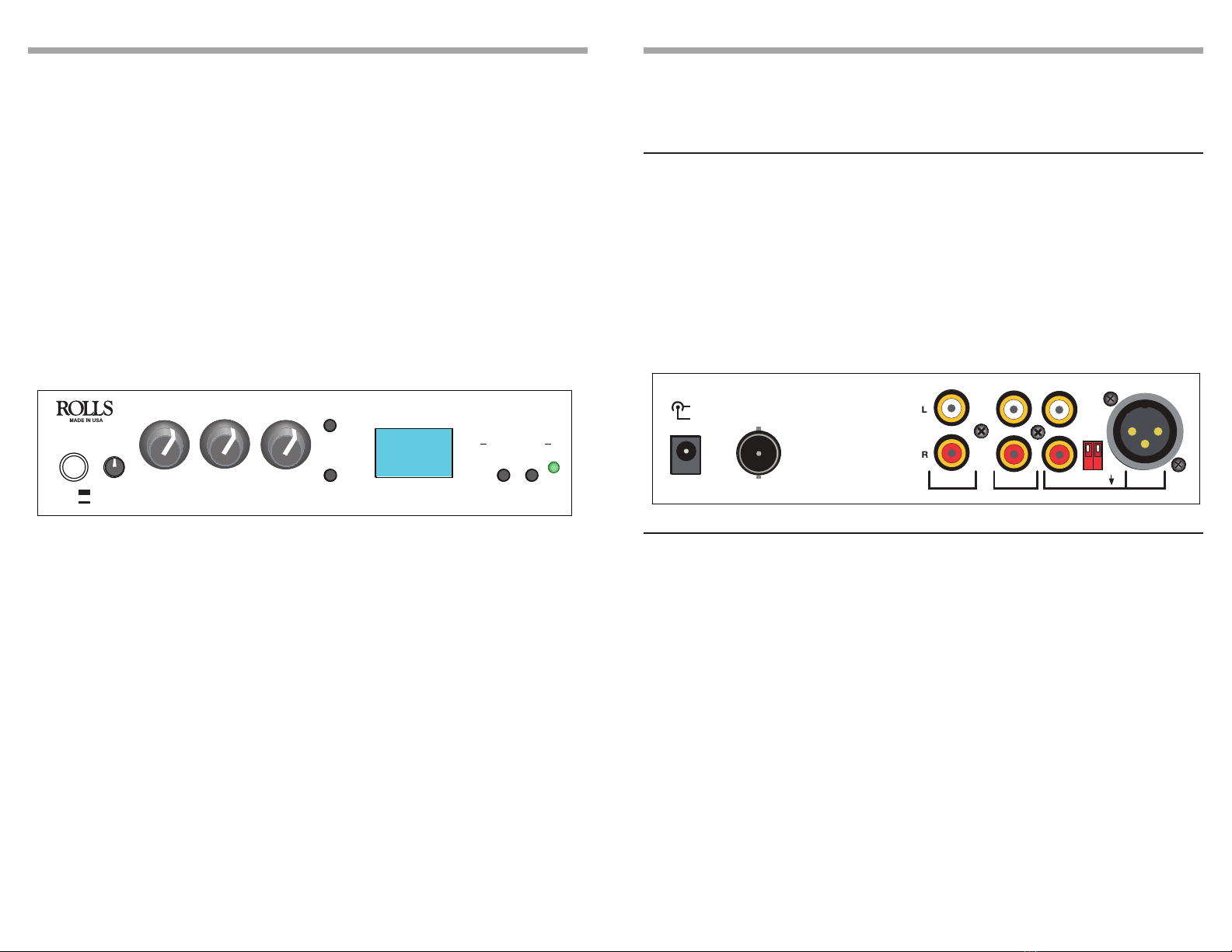
REAR PANEL
• 15VDC: USE THE ROLLS SUPPLIED PS27s ADAPTER ONLY!!!
• Aux In: The Aux in is an input that will talk over the Line In (Main input)
• Line in: This is the main line level input to the HR70.
• Outputs: RCA stereo outputs.
• Mic: XLR microphone input.
• ANTENNA: Connects to the included RP-SMA FM transmitting antenna.
HR70
FM TRANSMITTER
+
-
15 VDC
ANTENNA
FREQUENCY
DN UP
HR70
PWR
DUCK
MIC
MIC
LINE
RELEASE
TIME
MIC
AUX IN
LINE INOUTPUT
fast
slow
www.rolls.com
LEVEL
MUTE
CLIP
1 2
1 - TALK OVER OFF
2 - PHANTOM POWER
SENSITIVITY
LEVEL
ON
103.5MHz

Other Rolls Transmitter manuals

Rolls HR70 User manual

Rolls

Rolls HR70 User manual

Rolls HR70 User manual

Rolls

Rolls HR70 User manual

Rolls HR70 User manual

Rolls

Rolls HR70 User manual

Rolls HR70 User manual

Rolls

Rolls HR70 User manual

Popular Transmitter manuals by other brands

Marti Electronics STL-10 instruction manual

Marti Electronics

Marti Electronics STL-10 instruction manual

ADDER AdderLink DV104T user guide

ADDER

ADDER AdderLink DV104T user guide

TechnipFMC Proline 300 HART manual

TechnipFMC

TechnipFMC Proline 300 HART manual

ROBBE-Futaba FX-40 operating instructions

ROBBE-Futaba

ROBBE-Futaba FX-40 operating instructions

Warner RF FMT3.0 English Manual

Warner RF

Warner RF FMT3.0 English Manual

GREISINGER electronic GLMU 200 MP operating manual

GREISINGER electronic

GREISINGER electronic GLMU 200 MP operating manual

Sony DWT-P30 operating instructions

Sony

Sony DWT-P30 operating instructions

Emerson Rosemount 644 quick start guide

Emerson

Emerson Rosemount 644 quick start guide

Extron electronics VERSATOOLS MTP user guide

Extron electronics

Extron electronics VERSATOOLS MTP user guide

Worldcast Systems Ecreso Series user manual

Worldcast Systems

Worldcast Systems Ecreso Series user manual

Messtechnik optoUSB-3.0 manual

Messtechnik

Messtechnik optoUSB-3.0 manual

Risco Beam 7225 installation guide

Risco

Risco Beam 7225 installation guide

evertz 7700 MultiFrame manual

evertz

evertz 7700 MultiFrame manual

B-Speech Tx user manual

B-Speech

B-Speech Tx user manual

M-system Mini-M M2MS instruction manual

M-system

M-system Mini-M M2MS instruction manual

Technaxx FMT1500BT user manual

Technaxx

Technaxx FMT1500BT user manual

TFA 30.3110 manual

TFA

TFA 30.3110 manual

ATI Technologies A12-17 Operation and maintenance manual

ATI Technologies

ATI Technologies A12-17 Operation and maintenance manual

manuals.online logo
manuals.online logoBrands
  • About & Mission
  • Contact us
  • Privacy Policy
  • Terms and Conditions

Copyright 2025 Manuals.Online. All Rights Reserved.