Risco Beam 7225 User manual

‐1‐
IR Beam 72
(Beam 7225/Beam 7250/Beam 7275)
Installation Guide
1. Introduction
TheIRBeam72outdoordetectorsemploytwinbeamswithadvancedopticsandfourselectablechannels,providingreliabledetection.
2. Layout
Cover
Screw
WireEntry
4ChannelOptionSwitch
OpticalAxisMonitorJack(Receiver)
OpticalAxisRotation
ReflectorandFilter
BracketandBaseAttachingHoles
OpticalAxisWindows
OpticalAxisScrew
ResponseSpeedVR(Receiver)
TerminalBlock
13 LED
SenseLED
D‐beltforpolemounting
(purchasedseparately‐P/N:RBM72P00000A)
Bracket
3. Mounting Location 4. Installation Method
1.Mountthetransmitterandreceiverwithinmaximumrange.
2.Incasethereceivedsignalislow,installwithinrotationanglerange
ofthereflector.
3.Avoiddirectsunlight(facing
sunriseorsunset)or
headlamps.
4.Avoidobstacles(flowerpots,
laundry,pets)betweenreceiverand
transmitter.
5.Wheninstallingseveraldetectorsorcrossinstallationtoavoid
collisioninstallaccordingtothefollowingdiagram:
6.Donotinstallonunstable
surfaces.
7.Aftermounting,adjustoptical
axisandconductawalktest.
1.Toremovefrontcover,
unscrewfrontbottomscrew.
3.Mountondesiredwallorpole
andconnectwiresthroughwire
entry(seeterminalblock).
4.Connectthewirethroughthe
upperterminalblock.Replace
thebracketandfixingscrew.
2.Toseparatebracketfrom
detector,unscrewbottomscrew.
Whenmountingtwo
bracketsononepole,installa
pairofD‐beltsattheupperand
lowerpartsandinstallanother
D‐beltinthemiddleforequal
mountingheight.
5.Adjusttheopticalaxisand
conductawalktest.Then,
replacefrontcover.

‐2‐
5. Terminal Block 7. Response Time
•POWERInput:10V~28VDC(nonpolar)
•ALARMOutput:NC,30VDC/0.5A
•4.7KΩ(EndofLineTermination)
•TAMPER
6. Beam (Viewfinder) Adjustment
1.Afterconfirmingdetector
mountinglocation,adjustthe
reflectorangleusingtheview
finder.
2.Usingtheviewfinder,adjust
thereflectorʹslocationtobe
withinthedetectionrangeofthe
oppositedetector.
3.Toadjusttheaxisangle,turntheaxisleftorrightsideandupor
downwardwithascrewdriver.
Iftheoppositedetectorisnot
shownclearly,attachawhite
papercoveronthebackofthe
oppositedetector.Thedistance
betweentheinstallerand
viewfindershouldbeabout3‐
5cm(1.1ʺ‐1.9ʺ)toobservethe
oppositedetectorclearly.
TheResponseperiodadjustmentVRallowsyoutomatchthe
sensitivitytothesurroundingsandavoidfalsealarms.Slowersettings
reducesensitivity.
1
3.5
6
VRindicator1~22~33~44~5
(Default)
5~6
DetectiontypeQuick
running
JoggingQuick
pace
Normal
pace
Slow
pace
Detectionspeed0.05sec0.1sec0.2sec0.35sec0.5sec
8. Technical Specifications
ModelBeam7225Beam7250Beam7275
DetectionMethodInfraredphotoelectric
BeamChannelOption4channelssetbydipswitch
DetectionRange(Outdoor)25m(82ft)50m(165ft)75m(250ft)
DetectionRange(Indoor)50m(165ft)100m(328ft)150m(492ft)
ResponsePeriod0.05sec‐0.5sec
AlarmPeriodReceiver:Standby‐LEDis“OFF”,
Alarm‐LEDis“ON”
Transmitter:LEDis“ON”innormalsituation
AlarmOutputStandby:short,Alarm:disconnection
ContactPoint:30VDC/0.5A,
resistance:2.2Ω
OpticalAxisAdjustmentrangeHorizontal:±90°,Vertical:±5°
PowerInput10~28VDC(non‐polarity)
PowerconsumptionReceiver:22mA,Transmitter:12mA,±3mA
TamperCoverremoval
IPRatingIP44
Weight1.058kg(2.3lb)
OperatingTemperature‐20°Cto+55°C(‐4°Fto131°F)
StorageTemperature‐25°Cto+60°C(13°Fto140°F)
MaterialABSresin,Polycarbonate
9. External Dimensions
Fineadjustmentofanopticalaxis:
Anerrorcanbecausedintheinstaller’sfieldofvision.So,fine
adjustmentmustbeconductedusingabuilt‐inmonitorjackanda
tester.
4.Fineadjustmentmethod:
(1)Insert“+”ontestertoreceiver’spositivevoltage,“_”ontester
shouldconnectto“_”onreceiver.Turnthereceiverʹsreflectortothe
rightorleftsotestervoltageismaximized.Avoidblockingthe
reflectorwithyourhands.
Adjustment
monitor jack
Sense
LED
Tester
Receiver
* Non block Monitor
* Bottom block,
Top Monitor
Ifadjustedexactly,withoutablocktest,senseLEDisswitchedoff
andthemonitorvoltageiskeptconsistent.
(2)Refertothetablebelowfortesterindicatedvoltageandreliability.
Formaximumoutput,performfineadjustment.Preferably,adjust
testervoltagetohighsensitivity.(Powerinput:12VDC)
Tester
indicated
voltage
Sensitivity
(outdoor)
Sensitivity
(indoor)
Over6.1VHigh
Over5.8VSatisfactoryHigh
Over5.3VAverageSatisfactory
Over4.8VAverage
Below4.8V
Needs
adjustmentNeedsadjustment
RISCO Group Limited Warranty
RISCOGroupanditssubsidiariesandaffiliates(ʺSellerʺ)warrantsitsproductstobefreefromdefectsinmaterialsand
workmanshipundernormalusefor24monthsfromthedateofproduction.BecauseSellerdoesnotinstallorconnect
theproductandbecausetheproductmaybeusedinconjunctionwithproductsnotmanufacturedbytheSeller,Seller
cannotguaranteetheperformanceofthesecuritysystemwhichusesthisproduct.Sellerʹsobligationandliabilityunder
thiswarrantyisexpresslylimitedtorepairingandreplacing,atSellerʹsoption,withinareasonabletimeafterthedateof
delivery,anyproductnotmeetingthespecifications.Sellermakesnootherwarranty,expressedorimplied,andmakes
nowarrantyofmerchantabilityoroffitnessforanyparticularpurpose.Innocaseshallsellerbeliableforany
consequentialorincidentaldamagesforbreachofthisoranyotherwarranty,expressedorimplied,oruponanyother
basisofliabilitywhatsoever.Sellerʹsobligationunderthiswarrantyshallnotincludeanytransportationchargesorcosts
ofinstallationoranyliabilityfordirect,indirect,orconsequentialdamagesordelay.Sellerdoesnotrepresentthatits
productmaynotbecompromisedorcircumvented;thattheproductwillpreventanypersonalinjuryorpropertyloss
byburglary,robbery,fireorotherwise;orthattheproductwillinallcasesprovideadequatewarningorprotection.
Buyerunderstandsthataproperlyinstalledandmaintainedalarmmayonlyreducetheriskofburglary,robberyorfire
withoutwarning,butisnotinsuranceoraguarantythatsucheventwillnotoccurorthattherewillbenopersonal
injuryorpropertylossasaresultthereof.Consequentlysellershallhavenoliabilityforanypersonalinjury,property
damageorlossbasedonaclaimthattheproductfailstogivewarning.However,ifsellerisheldliable,whetherdirectly
orindirectly,foranylossordamagearisingunderthislimitedwarrantyorotherwise,regardlessofcauseororigin,
sellerʹsmaximumliabilityshallnotexceedthepurchasepriceoftheproduct,whichshallbecompleteandexclusive
remedyagainstseller.NoemployeeorrepresentativeofSellerisauthorizedtochangethiswarrantyinanywayorgrant
anyotherwarranty.
WARNING:Thisproductshouldbetestedatleastonceaweek.
Contacting RISCO Group
RISCOGroupiscommittedtocustomerserviceandproductsupport.Youcancontactusthroughourwebsite
www.riscogroup.comorasfollows:
UnitedKingdom
Tel:+44‐161‐655‐5500
technical@riscogroup.co.uk
USA
Tel:+1‐631‐719‐4400
support‐[email protected]
France
Tel:+33‐164‐73‐28‐50
support‐[email protected]
Israel
Tel:+972‐3‐963‐7777
Italy
Tel:+39‐02‐66590054
Brazil
Tel:+1‐866‐969‐5111
support‐[email protected]
China
Tel:+86‐21‐52‐39‐0066
support‐[email protected]
Belgium
Tel:+32‐2522‐7622
support‐[email protected]
Spain
Tel:+34‐91‐490‐2133
support‐[email protected]
Poland
Tel:+48‐22‐500‐28‐40
support‐[email protected]
Allrightsreserved.
Nopartofthisdocumentmaybereproducedinanyformwithoutpriorwrittenpermissionfromthepublisher.
©RISCOGroup09/095IN1281
This manual suits for next models
2
Table of contents
Other Risco Transmitter manuals

Risco
Risco WL T4RCP User manual
Risco
Risco RWX73F User manual
Risco
Risco RWX73M User manual
Risco
Risco WL T72C User manual
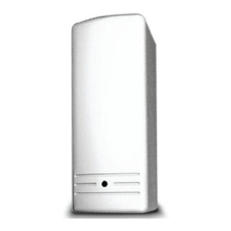
Risco
Risco WL T72C User manual
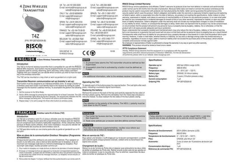
Risco
Risco T4Z User manual

Risco
Risco RP128T4RC User manual
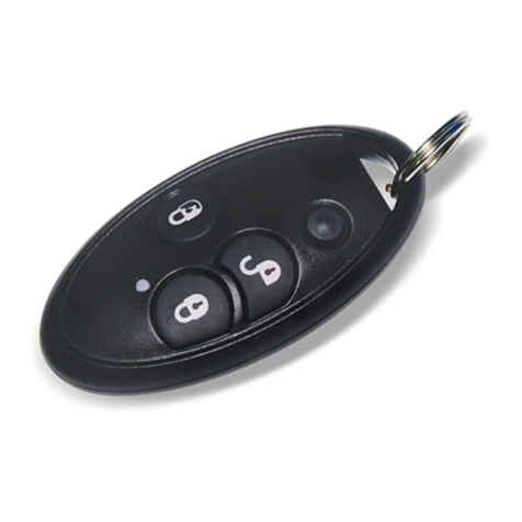
Risco
Risco 4 Button Rolling Code Keyfob User manual

Risco
Risco RWX73M User manual

Risco
Risco WL 132KF1 User manual
Popular Transmitter manuals by other brands

SI
SI KJ16 manual

AII
AII GPR-2500 manual

Zhongshan K-mate General Electronics
Zhongshan K-mate General Electronics AT1900 user manual
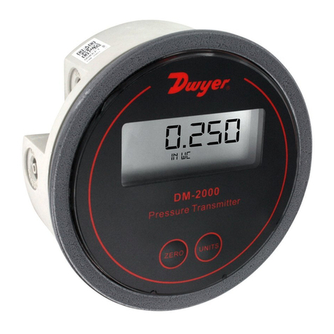
Dwyer Instruments
Dwyer Instruments DM-2000 Series Installation and operating instructions
Powercast
Powercast Powercaster TX91503 user manual
BWI Eagle
BWI Eagle 441-10100-AC Product information bulletin
