RollSeal RS-500 5K User manual

4801-5164J 20 October 2021
RS-500 5K Walk-In Cooler Door
Installation and Operation Manual
1

4801-5164J 20 October 2021
2
RS-500 5K Walk-In Cooler Door Installation and Operation Manual
Section 1: Introduction...........................................................................................................................................
Section 1.1: Definitions of Informational Headings...........................................................................................................................
Section 1.2: Scope of Manual..............................................................................................................................................................
Section 1.3: Limited Warranty.............................................................................................................................................................
Section 1.4: Components....................................................................................................................................................................
Section 1.4.1: RS-500 Walk-In Cooler Door.............................................................................................................................................
Section 1.4.2: Smart Controller...............................................................................................................................................................
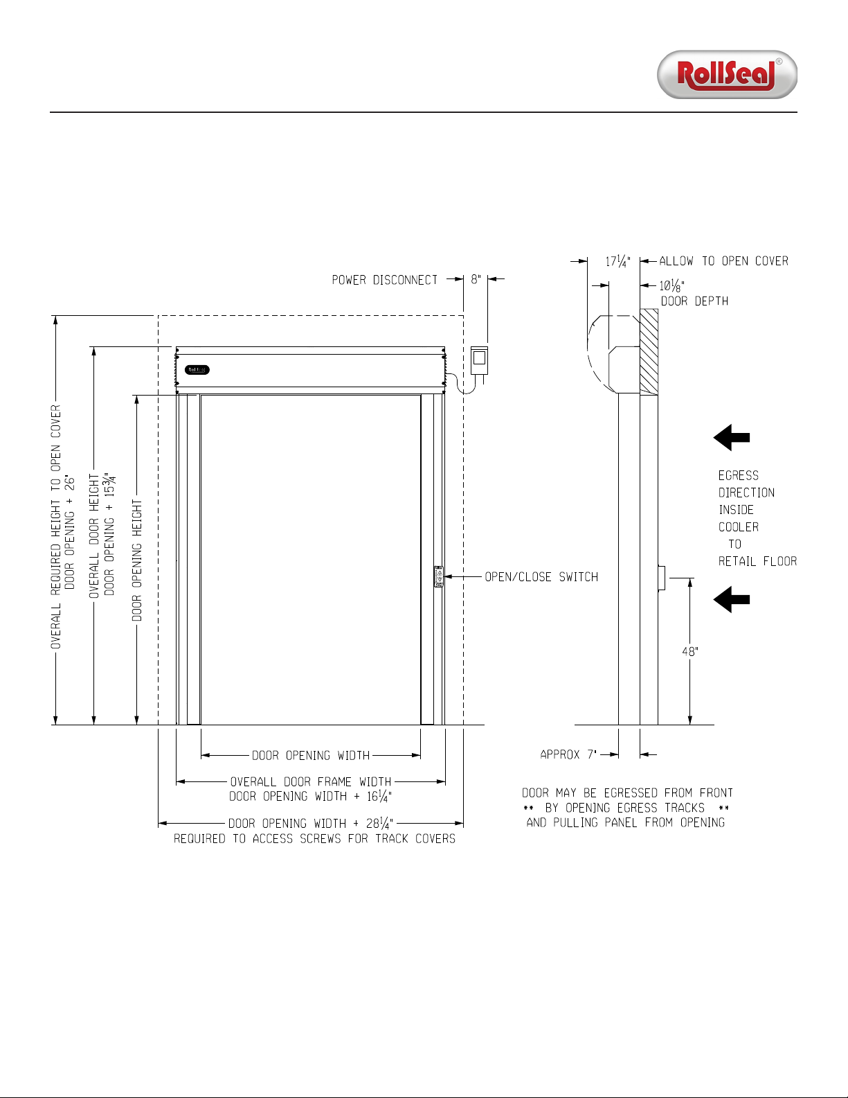
Section 1.5: Dimensions......................................................................................................................................................................
Section 2: Installation.............................................................................................................................................
Section 2.1: Preliminary Steps............................................................................................................................................................
Section 2.2: Adjust Framing and/or Clear Opening............................................................................................................................
Section 2.3: Connect Tracks to Head Unit..........................................................................................................................................
Section 2.4: Mount Door to Clear Opening.........................................................................................................................................
Section 2.5: Install Egress Track System.............................................................................................................................................
Section 2.6: Install Switches and Infrared Safety Beam.....................................................................................................................
Section 2.6.1: Interior Wave Switch........................................................................................................................................................
Section 2.6.2: Infrared Safety Beam System and Exterior Smart Switch..............................................................................................
Section 2.7: Connect Power to Door....................................................................................................................................................
Section 2.8: Install Power Disconnect.................................................................................................................................................
Section 2.9: Prepare for Operation......................................................................................................................................................
Section 3: Operation...............................................................................................................................................
Section 3.1: Activating Door.................................................................................................................................................................
Section 3.1.1: Switches and Smart Controller........................................................................................................................................
Section 3.1.2: Auxiliary Devices...............................................................................................................................................................
Section 3.2: Egress Track System........................................................................................................................................................
Section 3.3: Home and Auxiliary Safety Sensors; Leading Edge Switch............................................................................................
Section 3.4: Infrared Safety Beam.......................................................................................................................................................
Section 3.5: Power Switch...................................................................................................................................................................
Section 3.6: Communication Between Smart Controller and Door...................................................................................................
Section 3.7: Smart Controller User Interface......................................................................................................................................
Section 3.7.1: Overview...........................................................................................................................................................................
Section 3.7.2: Display Indicator Readings..............................................................................................................................................
Section 3.8: Configuration...................................................................................................................................................................
Section 3.8.1: Program Mode..................................................................................................................................................................
Section 3.8.2: Opening and Closing Speeds...........................................................................................................................................
Section 3.8.3: Deceleration Range..........................................................................................................................................................
Section 3.8.4: Open and Closed Limits...................................................................................................................................................
Section 3.9: Jog Mode..........................................................................................................................................................................
Section 3.10: Door Activation Inputs...................................................................................................................................................
Section 3.10.1: Directional Switch..........................................................................................................................................................
Section 3.10.2: Manual Switch................................................................................................................................................................
Section 3.10.3: Timed Switch..................................................................................................................................................................
Section 4: Maintenance...........................................................................................................................................
Section 4.1: Cleaning and Adjustment................................................................................................................................................
Section 4.1.1: Cleaning Panels and (if Present) Window.......................................................................................................................
Section 4.1.2: Adjusting Panels and Tension Pipes................................................................................................................................
Section 4.2: Component Replacement...............................................................................................................................................
Section 4.2.1: Egress Tracks....................................................................................................................................................................
Section 4.2.2: Panels...............................................................................................................................................................................
Table of Contents
4
4
4
5
6
6
8
9
10
10
10
12
13
15
17
17
18
20
21
22
23
23
23
23
24
25
26
27
27
28
28
29
31
31
36
37
37
37
38
38
38
38
39
39
39
39
40
40
41

4801-5164J 20 October 2021
3
RS-500 5K Walk-In Cooler Door Installation and Operation Manual
Section 5: Troubleshooting......................................................................................................................................
Section 5.1: Emergency Manual Operation.........................................................................................................................................
Section 5.2: P12 Input Status Indicators.............................................................................................................................................
Section 5.3: Error Codes and Recommended Actions........................................................................................................................
Section 5.4: Smart Controller/Smart Switch Error Indicators............................................................................................................
Section 5.5: Drive Board Diagnostic LEDs...........................................................................................................................................
Section 5.5.1: Door Idle............................................................................................................................................................................
Section 5.5.2: Door Moving......................................................................................................................................................................
Section 5.6: Testing Brake Relay..........................................................................................................................................................
Section 6: Wiring Diagrams......................................................................................................................................
Section 6.1: Switch Card and Safety Beams.......................................................................................................................................
Section 6.2: Head Unit.........................................................................................................................................................................
Section 6.3: Remote Receiver..............................................................................................................................................................
Section 7: Accessories.............................................................................................................................................
Section 7.1: Passive Infrared Motion Sensor.......................................................................................................................................
Section 7.2: Wave Close-Proximity Sensor..........................................................................................................................................
Section 7.3: Large Door Motion Sensor...............................................................................................................................................
Section 7.4: One-Button Control Station............................................................................................................................................
Section 7.5: Two-Button Control Station with Key Lock....................................................................................................................
Section 7.6: Pull-Cord Switch...............................................................................................................................................................
Section 7.7: Remote Receiver and Transmitter...................................................................................................................................
Section 7.8: Auxiliary Power Supply....................................................................................................................................................
Section 8: Replacement Parts..................................................................................................................................
Section 8.1: General.............................................................................................................................................................................
Section 8.2: Smart Controller..............................................................................................................................................................
Section 9: Warnings/Avertissements.........................................................................................................................
Table of Contents (Continued)
43
43
44
45
46
47
47
47
48
49
49
50
51
52
52
52
52
52
52
52
52
52
53
53
55
56

4801-5164J 20 October 2021
4
RS-500 5K Walk-In Cooler Door Installation and Operation Manual
Section 1.1: Definitions of Informational Headings
• DANGER: This heading indicates noncompliance with the stated information will lead to serious injury or death.
• WARNING: This heading indicates noncompliance with the stated information may lead to serious injury or death.
• CAUTION: This heading indicates noncompliance with the stated information may lead to minor or moderate injury.
• NOTICE: This heading draws attention to specific information.
Section 1.2: Scope of Manual
Section 1: Introduction
NOTICE: This document is subject to change without notice. The latest version is maintained at rollseal.net/rollseal-technicals/.
This manual describes the following aspects of the RollSeal RS-500 automated walk-in cooler door:
1. Installation of the door and its components.
2. Operation of the door and the SC-325M controller (henceforth referred to as the "Smart Controller"), including activation
methods and program configuration.
3. Maintenance, including cleaning, adjustment, and replacement of various components.
4. Troubleshooting, including diagnostic indicators and corresponding recommended actions, as well as manual operation.
5. Diagrams of the door and its components.
6. Accessory components, mostly including auxiliary activation options.

4801-5164J 20 October 2021
5
RS-500 5K Walk-In Cooler Door Installation and Operation Manual
Section 1.3: Limited Warranty
RollSeal, a division of HH Technologies, Inc., warrants the RollSeal Door ("the Product") to be free from defects in material and/or
workmanship for a period of either (a) one year from the date of invoice or (b) 100,000 cycles, whichever comes first, provided the
Product is installed and used in strict accordance with oicial documentation. Liability is limited to the sale price of the Product
or, at RollSeal's discretion, to the replacement of the Product upon its return.
This Limited Warranty excludes any labor, equipment, transportation, and/or service expenses that may be required to remedy the
warranted defect(s); all such charges must be funded by the purchaser. Neither the Product nor any of its component parts are to
be returned for repair or replacement until they have been inspected and/or a Return Goods Authorization (RGA) number has been
issued.
Complaints are to be directed first to the authorized distributor who sold the Product. If satisfaction is not obtained and/or the
distributor cannot be contacted, contact the Warrantor listed below, directed to the attention of "Customer Service Manager".
This Limited Warranty is void if (a) the Product and/or any of its component parts are found to have been misused, abused, or
otherwise tampered with by unqualified personnel; (b) any of the Product's component parts have been replaced by anything
other than authorized RollSeal replacement parts; (c) the Product has been modified in any way other than oicially sanctioned
upgrades made by qualified personnel using authorized RollSeal accessories; (d) the Product has not been appropriately
registered by its original purchaser; and/or (e) the customer cannot provide proof of purchase indicating them to be the Product's
original owner.
This Limited Warranty is made solely to the original purchaser of the Product. It cannot be transferred.
This Limited Warranty is in lieu of any and all other representations and/or warranties, expressed or implied, including any implied
warranty of merchantability and/or fitness for a particular purpose. The remedy set forth by this Limited Warranty shall be the
exclusive remedy available to any entity. No entity has the authority to bind RollSeal to any representation or warranty other
than this Limited Warranty. RollSeal shall not be liable for any damages or losses resulting from any application of the Product or
caused by any defect, failure, or malfunction of the Product.
This Limited Warranty gives you specific legal rights. You may have additional rights, as some areas do not allow the exclusion or
limitation of incidental or consequential damages. The above limitation or exclusion may therefore not apply to you.
Warrantor: HH Technologies (d.b.a. RollSeal)
Address: 1733 County Road 68; Bremen, AL 35033
Phone: 256-287-7000
Email: customerservic[email protected]

4801-5164J 20 October 2021
6
RS-500 5K Walk-In Cooler Door Installation and Operation Manual
Section 1.4: Components
Section 1.4.1: RS-500 Walk-In Cooler Door
Head Unit Cover
1/6 HP Motor
Aux. Safety Sensor
Smart Controller
Track Cladding
Track Cladding
Smart Switch
Egress Track System
Safety Beam
Emitter
Safety Beam
Receiver
RS-500 Walk-In Cooler (WIC) automated fabric roll-up doors are designed to separate diering environments. They are used in
various applications, including cold storage and environmental rooms. RS-500 WIC doors are manufactured up to 6' W x 9' H, have
a maximum speed of 27" per second, and are suitable for foot and pallet jack traic.
All RS-500 WIC doors have a fabric panel that consists of three layers of industrial-grade material. A dead air space between these
layers creates outstanding separation and insulation between the environments inside and outside the door. Each door model is
equipped with an NSF-grade patented sealing technology, as well as a patented Egress Track System that allows the user to easily
exit the cooler in an emergency.
Top Bar Cover End
Top Bar Cover End

4801-5164J 20 October 2021
7
RS-500 5K Walk-In Cooler Door Installation and Operation Manual
Technical Specifications
Power Supply 115VAC; 50/60 Hz; Single-Phase or 230VAC; 50/60 Hz; Single-Phase
Temperature Range 32°F to 115°F (0°C to 46°C)
Input 10A at 115VAC; Single-Phase or 6A at 230VAC; Single-Phase
Operational Power 3A at 115VAC; Single-Phase or 1.5A at 230VAC; Single-Phase
Standby Power 0.2A at 115VAC; Single-Phase or 0.1A at 230VAC; Single-Phase
Speed Up to 27" per Second
Horsepower 1/6 HP
Features
So Start/Stop Equipped
Programmable Control Equipped
Automatic Closure Equipped
Manual Override 3/4" Socket
Safety Beam System Monitored per UL 325
Tension Pipes Foam-Covered Fiberglass
Emergency Egress Egress Track System
Certifications
Energy Independence and Security Act Exempt
National Sanitation Foundation Certified
UL UL 325

4801-5164J 20 October 2021
8
RS-500 5K Walk-In Cooler Door Installation and Operation Manual
Section 1.4.2: Smart Controller
The Smart Controller is manufactured specifically for the RollSeal automated door. Located inside the head unit, it uses internal
safety devices, in conjunction with components of the door assembly, to open and close the door automatically. The Smart
Controller can also manage the opening and closing speeds of the door, count the number of door cycles, and provide status
information for remotely monitoring the door's position. Furthermore, the Smart Controller can incorporate several auxiliary
devices to improve the operation of the door:
1. Integrated infrared sensors can detect the presence of personnel and/or machinery requiring passage through the door.
2. Integrated auxiliary lights and/or audible alarms can be used to indicate the opening or closing of the door.
3. Auxiliary inputs (sold separately) can operate the door remotely. See Section 7 for details.
Drive Board PCB 201
Buzzer
Aux. IR Safety Sensor
Home Sensor

4801-5164J 20 October 2021
9
RS-500 5K Walk-In Cooler Door Installation and Operation Manual
Section 1.5: Dimensions

4801-5164J 20 October 2021
10
RS-500 5K Walk-In Cooler Door Installation and Operation Manual
Section 2: Installation
Read this manual in its entirety before beginning the procedure. Inspect the contents of the shipping crate for damaged, loose, or
missing components. If any components are damaged, loose, or missing, contact your RollSeal distributor immediately.
Section 2.1: Preliminary Steps
Installation Requirements
Door Size Personnel Equipment Tools PPE Time
Up to 6’ W x 9’ H 2 Ladder
- Standard Hand Tools
(Drill, Wrenches, Level, etc.)
- 1” Hole Saw (for Switch)
- Glasses
- Gloves
- Boots
- Hard Hat
~ 1 Hour
Section 2.2: Adjust Framing and/or Clear Opening
1. Using the diagram on the following page, determine the required dimensions of the clear opening. If necessary, adjust the
dimensions of the mounting posts and/or framing members to suit the nominal dimensions of the door.
2. The framing material must provide adequate support for screws. Ensure the mounting posts and/or framing members are
positioned so the screw holes in the vertical tracks will align with them.
3. Allow at least 12" (ideally 18") of clearance above the head unit.
4. Allow at least 6" of clearance on the outside of each track.
5. Ensure the top screw holes in the head unit will overlap and fit flush with the framing.
6. Ensure the screw holes in the vertical tracks align with the framing. The predrilled screw holes in the inner and outer flanges
will serve as attachment points when the assembly is mounted.

4801-5164J 20 October 2021
11
RS-500 5K Walk-In Cooler Door Installation and Operation Manual
Standard Diagonal Dimensions for Squaring Opening
x6' H 6.5' H 7' H 7.5' H 8' H 8.5' H 9' H
3' W 80-4/8" 85-7/8" 91-3/8" 96-7/8" 102-4/8" 108-1/8" 113-7/8"
3.5' W 83-3/8" 88-5/8" 93-7/8" 99-3/8" 104-6/8" 110-2/8" 115-7/8"
4' W 86-4/8" 91-5/8" 96-6/8" 102" 107-3/8" 112-6/8" 118-1/8"
4.5' W 90" 94-7/8" 99-7/8" 105" 110-1/8" 115-3/8" 120-6/8"
5' W 93-6/8" 98-3/8" 103-2/8" 108-1/8" 113-2/8" 118-3/8" 123-4/8"
5.5' W 97-5/8" 102-1/8" 106-7/8" 111-5/8" 116-4/8" 121-4/8" 126-5/8"
6' W 101-7/8" 106-1/8" 110-5/8" 115-2/8" 120" 124-7/8" 129-6/8"

4801-5164J 20 October 2021
12
RS-500 5K Walk-In Cooler Door Installation and Operation Manual
Section 2.3: Connect Tracks to Head Unit
1. Remove the cover from the head unit by releasing the two latches at the bottom, removing the Phillips-head screws as
needed, then pushing the cover upward. Set the cover aside.
2. Place the head unit face-down on a piece of cardboard.
3. Remove the cladding from the le track by removing the three screws from each side (six total). Once the screws have been
removed, pull the cladding upward and away from the track frame. Repeat this process on the right track cladding. Set the
screws aside to use when reinstalling the cladding in Section 2.6.2.
4. Align the upper track holes with the threaded holes on each end of the head unit.
5. Remove the three pre-installed 5/16" x 1" bolts from the head unit, then align the tracks with the bolt holes. Once the tracks
are aligned, reinstall the bolts and tighten them.
Latch Screw

4801-5164J 20 October 2021
13
RS-500 5K Walk-In Cooler Door Installation and Operation Manual
Section 2.4: Mount Door to Clear Opening
1. Ensure the door assembly is lying face-down with the bottoms of the tracks perpendicular to the bottom of the clear opening.
2. Slowly li the head unit until it is upright.
3. Walk the door backward, then slide the tracks until they contact the clear opening mounting structure.
4. Ensure the door assembly is square and level.
5. Ensure the mounting holes on the tracks and the back plate are aligned with the structural support members.
6. Secure the door assembly by installing the provided hex-drive rivets through the prepunched holes at the corners. For
all other prepunched holes, if mounting the assembly to metal, use the provided self-tapping screws or stitch screws. If
mounting the assembly to wood, use wood screws (not provided).
7. Ensure the bottoms of the tracks are square, then secure them to the floor using the provided concrete anchors.
NOTICE: If the tracks are not square, the safety beam will not function properly, triggering error code "PS" (see Section 5.4).
8. Reinstall the head unit cover by inserting the two downward-facing tabs on the back of the cover into the two slots at the top
of the door frame. Leave the cover open.

4801-5164J 20 October 2021
14
RS-500 5K Walk-In Cooler Door Installation and Operation Manual
Concrete Anchor
Hex-drive
Rivet
Self-tapping
Screw/Stitch
Screw (Metal)
or
Wood Screw
(Wood)
Hex-drive Rivet

4801-5164J 20 October 2021
15
RS-500 5K Walk-In Cooler Door Installation and Operation Manual
Section 2.5: Install Egress Track System
NOTICE: The le and right egress tracks are not interchangeable. A flange on each track is punched with the door height, followed
by either the letter "L" (le) or the letter "R" (right). For example, the image below depicts the le egress track for a 9' door.
1. Position the le egress track in front of the door, oriented as described above.
2. Align the L-shaped tab with the corresponding slot.
3. Pull the track down so the tab engages in the slot.
4. Repeat Steps 1-3 on the right track.
Tab
Height (X' - Y")
Side

4801-5164J 20 October 2021
16
RS-500 5K Walk-In Cooler Door Installation and Operation Manual
Tab Engaged
in Slot
Track
Open
Track Installed and in
Fully Open Position

4801-5164J 20 October 2021
17
RS-500 5K Walk-In Cooler Door Installation and Operation Manual
1. Drill a 1" hole in the wall in line with the 1" hole in the back of the right track, approximately 4' above the floor.
2. Route the harness from the back to the front through the hole you just drilled.
3. Apply sealant (ideally waterproof silicone; not included) around the harness from the back.
NOTICE: If the sealant is not applied or is applied incorrectly, condensation can form inside the switch enclosure.
4. On the inside of the door, center the Wave Switch bracket over the 1" hole in the base of the enclosure (orienting it with the
flanges at the top and bottom), then mount the enclosure to the wall using four screws. Ensure the enclosure remains level.
5. On the outside of the door, position the right track cladding next to the track frame.
6. Route the harness through the holes, then plug the two connectors into the corresponding receptacles on the front Wave
Switch.
7. Apply one of the "Moving Door" labels (4501-6312) 3" above the switch enclosure.
Section 2.6.1: Interior Wave Switch
Section 2.6: Install Switches and Infrared Safety Beam System

4801-5164J 20 October 2021
18
RS-500 5K Walk-In Cooler Door Installation and Operation Manual
Section 2.6.2: Infrared Safety Beam System and Exterior Smart Switch
1. Locate the three-wire harness inside the head unit between the motor and the Smart Controller.
2. Route the harness under the motor, through the grommet on the le end plate, and through the large holes in the braces on
the le track, then plug it into the safety beam connector. Coil any excess length and secure it to the inside track frame.
3. Reinstall the cladding on the le track by feeding it at an angle, pushing it upward against the rubber seal at the head unit,
pushing it in toward the track frame, and sliding it toward the track frame at the floor. Secure it using the screws you removed
in Section 2.3.
4. Locate the harness with a 20-pin connector to the right of the Smart Controller.
5. Route the harness through the grommet at the bottom of the right end plate, then route it through the large holes in the
braces on the right track.
6. Plug the 20-pin connector into the receptacle on the back of the switch card.
7. Locate the harness with a 4-pin connector next to the sensor in the right track.
8. Uncoil the harness, then route it up the right track, through the large holes in the track braces, and to the Smart Switch.
9. Plug the harness into the 4-pin receptacle on the back of the Smart Switch, matching the yellow dot on the harness clip to the
yellow dot on the switch card to avoid damaging the switch card.
10. Coil the excess length and secure it to the inside track frame, but leave enough slack for a service loop.
11. Reinstall the cladding on the right track by feeding it at an angle, pushing it upward against the rubber seal at the head unit,
pushing it in toward the track frame, and sliding it toward the track frame at the floor. Secure it using the screws you removed
in Section 2.3.
12. Apply the other moving "Moving Door" label (4501-6312) 1" to the right of the track.

4801-5164J 20 October 2021
19
RS-500 5K Walk-In Cooler Door Installation and Operation Manual
20-pin Connector
Rear Prewired
Switch Harness
4-pin Connector
for IR Safety Sensor

4801-5164J 20 October 2021
20
RS-500 5K Walk-In Cooler Door Installation and Operation Manual
Section 2.7: Connect Power to Door
NOTICE: The door is designed to accept either a 115VAC or 230VAC power supply.
1. Ensure the voltage selection switch at the bottom right of the control board is set to the appropriate voltage.
2. Mount the circular plastic connector (CPC) bracket to the right track using the provided hardware.
WARNING
Do not turn the power on until the following conditions have been met:
• All wire and cable connections are completed.
• The voltage selection switch is set to match the required supply voltage.
This manual suits for next models
1
Table of contents
Other RollSeal Air Conditioner manuals
Popular Air Conditioner manuals by other brands

Taurus
Taurus ALPATEC AC 201 manual

Olimpia splendid
Olimpia splendid Unico Twin Instructions for use and maintenance

LG
LG LP6011ER owner's manual

Panasonic
Panasonic CS-PZ25TKE operating instructions

Mitsubishi Electric
Mitsubishi Electric Mr. Slim PCA-RP-HAQ installation guide

Honeywell
Honeywell HB12CESV Series user manual

Innova
Innova 2.0 Instructions for installation, use and maintenance manual

Samsung
Samsung MWR-SH10N user manual

Fujitsu
Fujitsu AB A30TATA Series operating manual

Fujitsu
Fujitsu AIRSTAGE ASTH18CNTA Operation manual

Haier
Haier HCFU-18CF03 Service manual

Fujitsu
Fujitsu AU G18LVLB Series Design & technical manual