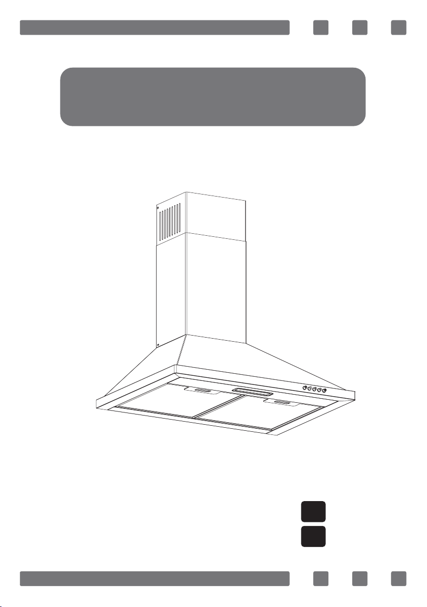
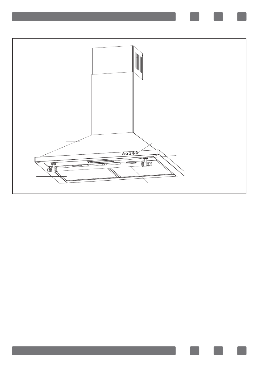
ROMMER D651 User manual

H10-20-300-048-Rev 003
GBUSER’S MANUAL
STANDARD COOKER HOOD
CAMPANA EXTRACTORA ESTÁNDAR
ESMANUAL DEL USUARIO

2
Dear Customer,
Thank you for choosing this product. We aim to ensure that you optimally
and efciently use this product produced in our modern facilities under
environmentally friendly and precise conditions with respect to total
sense of quality.
We advise you to read this user manual thoroughly before using the
hood and keep it permanently so that the features of the hood you have
purchased will stay the same as the rst day for a long time and it will
serve efciently.
This product has been produced in modern environmentally-friendly
facilities without harming the nature.
Complies with WEEE Regulation. Does not include PCB.
Note: This Operating Manual is prepared for multiple models. Your
appliance may not feature some functions specied in the manual.
These functions are marked by the sign *.
ATTENTION: READ THE INSTRUCTIONS BEFORE TESTING
OR USING THIS DEVICE.
GB

3
Table of Contents
Safety instructions ............................................................ 4
General appearance .......................................................... 7
Accessories ...................................................................... 8
Assembly ......................................................................... 9
Operation of the hood........................................................ 15
Control panel.................................................................... 17
Maintenance and cleaning ................................................. 17
Efcient use of the device ................................................. 19
Transporting the device ..................................................... 19
Service and spare parts ..................................................... 20
Troubleshooting ................................................................ 20
Packing information .......................................................... 21
Compliance with WEEE regulations and waste disposal......... 21

4
SAFETY INSTRUCTIONS
1. It is recommended that the product is installed by
authorized persons. Installation by unauthorized per-
sons could lead to poor operation performance, dam-
age to the product, and accidents. The product will not
be covered by the warranty.
2. Electric cooker hoods shall not be connected to
a ue or air duct that is used to discharge the smoke
from devices that use gas or other fuels (stove, water
heater, thermosiphon, etc.). This warning does not ap-
ply to uses without ue.
3. Comply with the regulations of the authorities on
the discharge of outlet air. (not applicable for devices
that discharge air back into the room)
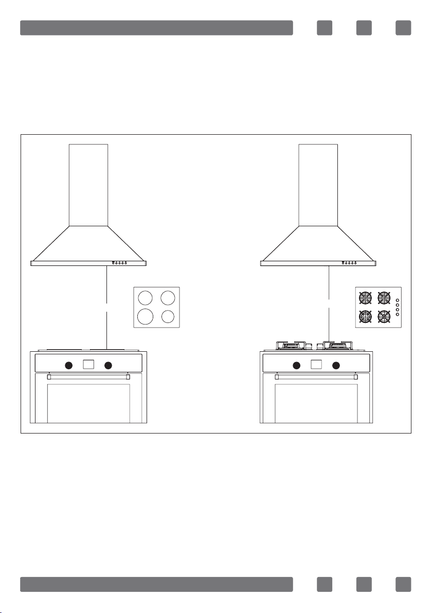
4. When the cooker hood is placed on a gas burning
device, the distance between the hob and the hood
should be at least 65 cm. If a larger distance is spec-
ied in the installation instructions of the gas burning
hob, this value should be taken into account.
5. While the hood is running, ensure fresh air can en-
ter the environment; especially when used at the same
time with ovens that use gas and appliances that use
solid and gas fuel.
6. For your safety, use ”Max 6 A” fuses in the hood
installation.
7. Do not leave boiling oil on the stove. Pots that con-
tain boiling oil may catch re by themselves.
GB

5
8. Do not operate the stove without cookwares placed
on them. High heat may cause some parts of your prod-
uct to deform and lead to re.
9. The packages pose a danger to children. Never al-
low children to play with packaging materials. Keep
packaging materials out of reach of children.
10. Clean the oil absorbent aluminum lters regularly.
Filters pose risk of re due to accumulated grease de-
posits on them.
11. Do not operate your product without lter, and do
not remove the lters when the product is in operation.
Do not use ltering materials that are not re-resistant
instead of the lter.
12. Flammable foods must not be cooked under the
appliance.
13. In case of any re, de-energize the device. Cover
the ames with a damp cloth or towel. Never use water
to extinguish the re.
14. Failure to comply with deadlines and instructions
while cleaning may result in a re hazard.
15. This device should not be used by children, per-
sons with physical, sensory or mental disabilities, per-
sons lacking experience or technical knowledge. Do
not allow the persons and children that are not under
custody to use the product, play with the product, to
perform maintenance and cleaning on the product.

6
16. Kitchen hoods are designed for domestic use.
They should not be used for other purposes. Otherwise,
it may cause various accidents and the device will be
out of warranty.
17. The electrical connection of the product must be
made to a grounded outlet.
18. The electrical connection should only be made once
the installation of the appliance has been completed.
19. Before the installation, maintenance and cleaning
of the product, de-energize the device. (Unplug the de-
vice or turn off the fuse).
20. It is forbidden to install the power cord near equip-
ment or materials that may come into contact with wa-
ter and cause distortion of the cord. This may cause
re.
21. Avoid touching the lamps in your product when
they have been operating for a long period of time.
Since they would be hot, they could burn your hand.
22. Accessible sections may be hot when used with
cooking appliances.
23. Failure to install screws or fasteners in accordance
with these instructions may result in electrical hazards.
24. Your device is manufactured in accordance with
220-240 V 50Hz AC power supply and requires a fuse
of 16 Amp. Should your electrical system differ from
these specied values, contact a licensed electrician or
your authorized service center.
GB

7
GENERAL VIEW
Note: Product images are representative. Product may vary in size and
model.
1. Inner ue
2. Outer ue
3. Body
4. Filter
5. Control panel
6. Light
7. Handle *
1
2
35
6
7
4

8
ACCESSORRIES
Inner Flue
Product body Outer Flue
Inner Flue Connection Sheet Ø8 Dowel - x 2 Ø4.8 x 50 Screw - x 2
Ø3.9 x 30 Screw - x 2 Ø6 Dowel - x 2 Flap - x 2
* *
Ø3.5 x 9.5 Screw - x 4 Handle Handle screw - x 2
Printed documents
GB

9
INSTALLATION
Mounting Distances
Distance between the cooker and the cooker hood must be considered
prior to assembly. The distance between the hob and the hood shall be at
least 65 cm.
Min. 65 cm Min. 65 cm

10
Body Mounting
Drill the product from points Awith a Ø8 drill bit and from points Bwith
a Ø6 drill bit as per the dimensions given below. Tap Ø8 and Ø6 dowels.
From the points A, perform installation to the body with a Ø5 x 50 mm
screw; and from points B, perform installation to the inner ue connection
plate with a Ø3.9 x 30 mm screw.
Note: The dimensions provided above are determined by considering
the distance between the lower contact point of the cooking pot and the
bottom of the hood is 650 mm
.
Min. 870
8
9
7
B
12
160
5
6
220
A
138
GB

11
Carbon Filter Assembly
Open the product cover and take out the aluminum lter. Turn the carbon
lter in the direction of the arrow by pressing the sides. (see Fig. 1-2)
Flap Assembly
Air Discharge valve prevents the entry of foreign bodies in the engine
group in the installation of the products with a ue. Install the ap as
shown in Figures 3 and 4 by removing the product from the installation
package.
Figure 1
Installation Direction
Figure 2
Direction of Removal
A
AB
B
Flap
plastic
Figure 3 Figure 4

12
Mounting of Aluminum Pipe
Mount the exible aluminum pipe on the ue. Install the other end
of the pipe to the ue hole in the kitchen. Spiral tube and screw clamp
are not included in the product accessories. They should be purchased
additionally. (See Fig. 6)
Note: Aluminum spiral tube is used for connections with ue.
Since twists and bends in the aluminum pipe will lead to reduction in
the air suction power, avoid formation of twists and bends as much as
possible. (see Fig. 7-8)
Figure 5 Figure 6
Spiral tube
Screwed clamp
Air outlet
Hood body
Figure 7 Figure 8
GB

13
Flue Installation
Secure the external ue to the body with 2 pieces of Ø3.5 x 9.5 mm screws
as shown in Figure 9. Secure the inner ue to the inner ue connection
plate with 2 pieces of Ø3.5 x 9.5 mm screws as shown in gure 10.
1. Outer Flue
2. Ø3.5 x 9.5 mm Screw x 4
3. Chimney connection sheet x 1
4. Inner Flue
Figure 9
1
2
Figure 10
3
4

14
Installation of the Handle *
To install the handle, remove the lters rst as shown in Figure 11.
After aligning the handle with the installation holes as shown in gure 12,
tighten the handle screw to the handle from the interior of the hood.
Figure 11 Figure 12
GB

15
USE OF THE HOOD
Hood may be used in kitchens with or without ue.
Air Outlet Connection
Air discharge can be done by ue connection (air discharge to the external
environment) or by ltering the air back to the environment (carbon lter).
Operation with Flue Connection
The absorbed air is delivered to a ue or outdoor environ-
ment with the help of a pipe attached to the blower motor
outlet of the hood in use with ue connection.
For ue-connected operation, Ø120 mm spiral pipe and clamp must be
provided from an authorized service or a point recommended by service.
Flueless operation
During ueless operation, the air sucked by the activated
carbon lter mounted on the blower motor side parts or
hood body is ltered and returned to the environment.
WARNING: In case of installation to a chimney, it is
necessary to note all relevant warnings in the safety and
environmental instructions.
WARNING: These parts are not included in the product
content and must be purchased.
WARNING: Since carbon lters are optional parts, they
must be purchased from the service at an additional fee.
Never wash the carbon lter.

16
Usage of the Carbon Filter
The product you are using has a feature of carbon lter usage.
Grease lters must be installed in the product, regardless of whether
carbon lters are used or not. Do not use your product without grease
lter.
Usage of carbon lter is as specied below.
De-energize your appliance before replacing the carbon lter.
Carbon lter shall be replaced once every 3-5 months depending on the
operation frequency because it is used in kitchens with no ue outlet.
Carbon lters shall never be washed.
Installation of the Carbon Filter
Carbon lters are used in kitchens without a ue outlet.
Carbon lters shall be installed on both sides of the fan by rotating them
clockwise for 10 degrees as shown in Figure 13.
Reverse this procedure for removal.
Usage of the Aluminum Cassette Filter
Aluminum cassette lter captures the dust and oil in the air. Do not ever
operate the hood without an aluminum cassette lter. (see Fig. 14)
Figure 13
Installation
Direction
Figure 14
GB

17
CONTROL PANEL
Push Button: Pressing the buttons activates different functions. To turn
them off, simply press the button.
MAINTENANCE AND CLEANING
1. Pay attention to clean the appliance, especially immediately after
cooking fried foods.
2. It is sufcient to use a soft cloth soaked in liquid detergent to clean
the exterior of the unit.
3. Never use abrasive or scratching products for cleaning.
4. In order to preserve the surface quality of the unit, avoid using cleaning
agents containing methylated spirits,bleach and abrasive powder when
cleaning. On stainless surfaces; use damp, soapy cloths or special cleaning
spray used for preferably stainless surfaces.
Motor operates at medium speed.
Turns off the motor.
(Excluding the lighting system) Motor operates at maximum speed.
Motor operates at low speed. Turns the light on and off.
WARNING: Prior to each maintenance and cleaning, the
unit must be unplugged or the fuse to which it is connected
must be turned off.
WARNING: Without periodic cleaning, there is a risk of
re and loss of performance.

18
Cleaning of Aluminum Filter
The lter helps to keep the oil particles in the air. It is recommended to
clean your lter once a month for normal use. Wash and rinse the lters in
the dishwasher or with a uid detergent and install them to their positions
after drying them.
Removal of Aluminum Filter
Pull the aluminum lter by pressing
it down as shown in gure 15.
Reverse the process to install the
lter.
Note: Avoid bending the aluminum
lter to prevent damage.
WARNING: When washed, discoloration can be ob-
served in aluminum lters. This is normal, you don't need
to change your lters.
WARNING: If the aluminum lter is not cleaned periodi-
cally, the oil accumulated on it creates a risk of re.
Figure 15
GB

19
EFFICIENT USE OF THE DEVICE
Use pipes with a diameter of 120 mm and few elbows as much as pos-
sible while connecting the hood to the ue.
Pay attention to the cleaning periods of the metal lters and replace-
ment periods of the carbon lters.
Use the device in the middle stage when it does not require intensive
suction power.
TRANSPORTINGTHE DEVICE
Save the original packaging of the device. Transport the device in its
original packaging, follow the transportation markings on the packaging.
If the Original Package of the Device Is Not Available;
Avoid putting weight on the device.
Protect the outer surface from impacts.
Carry the device by packing it in such a way that it is not damaged.

20
SERVICE AND SPARE PARTS
Spare parts for your device can be obtained from your dealer or authorized
service.
Upon contacting your service department or dealer, please indicate
the product model name that you can see on the unit label to request
replacement parts.
Once you remove the aluminum lter, you can see the label on the unit.
Check your device according to the table below before contacting the
service. If the problem persists, contact your dealer or an authorized
service.
TROUBLESHOOTING
Error Description Solution
The cooker hood
does not work.
Check the electrical connection.
Check engine switch. The engine switch should be in the on
position.
Lighting lamp
does not work.
Check the electrical connection.
Check lamp switch. Lamp switch must be at "on" position.
Air suction of the
hood is weak.
Check the aluminum lter. Aluminum lter should be washed once
a month under normal conditions.
Check the air outlet ue. The air outlet ue must be open.
Check the carbon lter. (For models with a carbon lter). Carbon
lter shall be replaced every 3 months under normal conditions.
Does not give
air outside. (in
environments
without ues).
Check the aluminum lter. Aluminum lter should be washed once
a month under normal conditions.
Check the carbon lter. (For models with a carbon lter). The carbon
lter shall be changed every 3 months under normal conditions.
GB
This manual suits for next models
1
Table of contents
Languages:
Other ROMMER Ventilation Hood manuals
Popular Ventilation Hood manuals by other brands

DeLonghi
DeLonghi TAFR60S user guide

KOBE
KOBE RA-094 Installation instructions and operation manual

VALBERG
VALBERG TSH 90 T X 962C(V2) instruction manual

ROBLIN
ROBLIN VIZIO 900 V BLAC SM Instructions for installation and use

Primada
Primada PRH900 instruction manual

Zephyr
Zephyr Spruce AK9834BS Use, care and installation guide