Romotop DYNAMIC B2G 66.50.13N User manual


ROMOTOP spol. s r.o., issued on 1 November 2017 Revised Nov 2017 ROMOTOP GmbH, herausgegeben am 01.11.2017 Revision 11/17
DE
EN
Product sheet under Regulation EU 2015/1186
Supplier's name or trademark: Romotop spol. s r. o.
Supplier's model identifier: DYNAMIC B 2G 66.50.13N
The energy efficiency class of the model: A+
The direct heat output in (kW): 4,8
The indirect heat output in (kW): 0
The energy efficiency index EEI: 113
The useful energy efficiency at nominal heat output (%): 84,6
The useful energy efficiency at minimum load (%): Pass
Special requirements (instalation, maintanance): See instructions
The information in the product sheet of the local space heater shall be provided in the
following order and shall be included in the product brochure or other literature provided
with the product.
EU 2015/1186
Name oder Warenzeichen des Lieferanten: Romotop GmbH
Modellkennung des Lieferanten: DYNAMIC B 2G 66.50.13N
Energieeffizienzklasse des Modells: A+
D (kW): 4,8
I (kW): 0
Energieeffizienzindex EEI: 113
(%): 84,6
Energieeffizienz bei Mindestlast (%): Pass
Besonderen Vorkehrungen (bei der Installation oder Wartung): siehe Anleitung
bereitgestellte Unterlagen aufzunehmen.

ROMOTOP S.A.R.L., 1/17 ROMOTOP spol. s r.o., rilasciato il 01.11.2017 Revisione 11/17
IT
FR
EU 2015/1186
Le nom du fournisseur ou la marque commerciale: Romotop S.A.R.L.
L : DYNAMIC B 2G 66.50.13N
L : A+
La puissance thermique directe en (kW): 4,8
La puissance thermique indirecte en (kW): 0
L EEI: 113
L (%): 84,6
L (%): Pass
cifiques (lors de l'assemblage, de la maintenance) : Cf. instructions
-
autre document fourni avec celui-ci.
Scheda prodotto secondo normativa EU 2015/1186
Nome oppure oppure marchio del fornitore: Romotop spol. s r. o.
Codice prodotto del fornitore: DYNAMIC B 2G 66.50.13N
classe di efficienza energetica del modello: A+
potenza termica diretta in (kW): 4,8
potenza termica indiretta in (kW): 0
indice di efficienza prodotto EEI: 113
efficienza del combustibile con potenza termica nominale (%): 84,6
efficienza del combustibile con carico minimo (%): Pass
precauzioni speciali ( ): Vedi introduzione
da indicare nella seguente successione e da inserire nel depliant o qualsiasi altro catalogo in
riferimento al prodotto.

EN DE FR IT
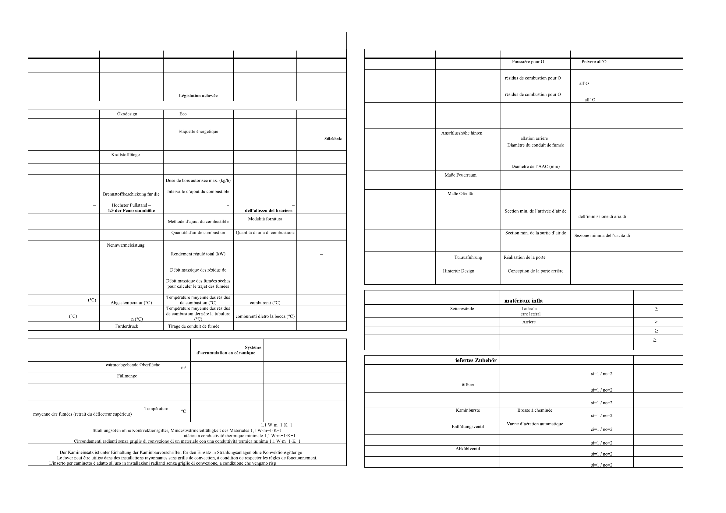
Product name Produktbezeichnung Nom du produit Nome del prodotto Dynamic B 2G
66.50.13N
Dimensions HxWxD (mm) Abmessungen HxBxT (mm) Dimensions HxLxP (mm) Dimensioni AxLxP (mm) 1091 x 720 x 464
Weight (kg) Gewicht (kg) Poids (kg) Peso (kg) 179
Completed legislation Abgeschlossene
Gesetzgebung Legislazione completata -
EN 13 229 / 15a B-VG / DIN plus / BImSch V 1 / BImSch V 2
Eco-design (%) (%) -conception (%) Eco-design (%) 75,6
EEI EEI EEI EEI 113,7
Energy Label Energielabel Etichetta energetica A+
Prescribed fuel Vorgeschriebener Brennstoff Combustible prescrit Combustibile prescritto Piece wood /
Morceau de bois / Pezzo
di legno
Fuel length (mm) (mm) Longueur de carburant (mm) Lunghezza del carburante
(mm) 330
Average wood consumption (kg/h)
Durchschnittlicher
Holzverbrauch (kg(h) Consommation de bois moyenne
(kg/h) Consumo medio di legna
(kg/ora) 1,33
Max. allowed wood batch (kg/h) Max. erlaubte Holzzuladung
(kg/h)
Dose massima di legna
consentita (kg/ora) 1,9
Fuel supply interval for the rated
output
Zeitabstand der
Nennleistung pour la puissance nominale
Intervallo fornitura
combustibile per potenza
nominale
1. hour, Stunde, heure,
ora
The greatest height of the filling
1/3 of the firebox Hauteur maximale de la charge
1/3 de la hauteur du foyer Altezza massima caricamento
1/3 -
Fuel delivery method Art der Brennstoffbeschickung
combustibile
manually, von Hand,
manuellement,
manualmente
Amount of combustion air (m3/h) Menge an Verbrennungsluft
(m3/h)
(m3/h) (m3/h) 16,9
Nominal heat output (kW) (kW) Puissance nominale (kW) Potenza nominale (kW) 4,8
Total regulated output (kW) Reg. Gesamtleistung (kW) Potenza totale regolata (kW) 2,4 6,2
Efficiency (%) Wirkungsgrad (%) Rendement (%) Efficienza (%) 84,64
Mass flow rate of dry flue gases
(g/s) Massendurchfluss der
trockenen Abgase (g/s) combustion secs (g/s) Flusso peso combustib
ile secco
(g/s) 4,1
Dry flue gases mass flow to
calculate the flue path (g/s)
Massendurchfluss von
trockenen Abgasen den
Schornsteinpfad berechnen(g/s)
(g/s)
Portata massica dei fumi secc
hi
per calcolare il percorso dei
fumi (g/s) 6,1
Average flue-gas temperature
Durchschnittliche Temperatura media gas
208
Average flue gas temperature after
Flue pipe
Durchschnittliche
Abgastemperatur hinter dem
Stutze
Temperatura media gas
241
Flue draught (Pa) (Pa) (Pa) Tiraggio del camino (Pa) 10
Ceramic accumulation system /
Keramisches Zugsystem / /
Sistema di accumulo di ceramica
Accumulation rings / Aufsatzspeicher
Set Ringe / Anneaux de l'ensemble de
rangement des accessoires / Set di
archiviazione degli attacchi Anelli
Minimum radiant area / Mindest- /
Surface radiante minimale / Area radiante minima 3,5 ---
Maximal load of wood / Maximal Brennstoff- /
Charge maximale
du bois / Carico massimo di legno kg 3,5 ---
Total heat output of the fireplace chamber / Feuerungsleistung / Puissance
thermique totale de la chambre du foyer / Potenza termica
totale della camera
del camino kW
11,0 ---
Average flue gas temperature (upper deflector removal) / Durchschnittliche
Rauchgastemperatur (Entfernen des oberen Deflektors) /
/ Temperatura media
dei gas di scarico (rimozione del deflettore superiore)
375 ---
Radiant surrounds without convection grids from a material with minimal thermal conductivity
Enveloppes rayonnantes sans grilles de convection en m
The fireplace insert is suitable for use in radiant fireplaces without convection grilles if the stove rules and regulations are followed.
eignet.
ettate le regole della stufa.
EN DE FR IT
Dust at O2 = 13%
(mg/Nm3) Staub bei O2= 13 %
(mg/Nm3) 2= 13%
(mg/Nm3) 2= 13 %
(mg/Nm3) 24
The concentration of CO
in the flue
gases at O2= 13% (mg/Nm3)
CO Konzentration in den
Abgasen bei O2= 13%
(mg/Nm3)
Concentration en CO dans les
2=
13% (mg/Nm3)
Concentrazione CO nei gas
comburenti
2
= 13 % (mg/Nm3) 1130
The concentration of CO
in the flue gases
at O
2
= 13% (%)
CO Konzentration
in den Abgasen
bei O
2
= 13% (%)
Concentration en CO dans les
2=
13% (%)
Concentrazione CO
nei gas comburenti
2
= 13 % (%) 0,0900
CO2 (%) CO2 (%) CO2 (%) CO2 (%) 9,54
OGC - 02=13% (mg/m3) OGC - 02=13% (mg/m3) OGC - 02=13% (mg/m3) OGC - 02=13% (mg/m3) 37
NOx - 02=13% (mg/m3) NOx - 02=13% (mg/m3) NOx - 02=13% (mg/m3) NOx - 02=13% (mg/m3) 118
Connection height for rear
installation (mm) (mm) Hauteur de raccordement pour
l'inst (mm) Altezza di collegamento per
l'installazione posteriore (mm)
-
Flue pipe diameter (mm) Rauchabfuhrdurchmesser (mm)
(mm) Diametro del condotto fumi
(mm) 150 200
Flue throat (mm) Flue Hals (mm) Flue la gorge (mm) Fumi gola (mm) 200
CAI diameter (mm) CPV-Durchmesser (mm) Diametro ACA (mm) 150
Dimensions of the
combustion
chamber HxWxD
(mm)
HxBxT
(mm) Dimensions de la chambre de
combustion HxLxP
(mm)
Dimensioni della camera di
combustione AxLxP
(mm)
457 x 574 x 180
Dimensions of the furnace
door HxWxD
(mm)
HxBxT
(mm) Dimensions de la porte du four
HxLxP
(mm)
Dimensioni della porta del
forno AxLxP
(mm)
456 x 619
Min. cross section of convect air
inlet for nominal output
(cm2)
Min. Querschnitt der
Konvektionsluftzufuhr f. die
Nennleistung
(cm2)
convection pour rendement
nominal
(cm2)
Sezione minima
convezione per la potenza
nominale (cm2)
500
Min. cross section of convect air
outlet for nominal output
(cm2)
Min. Querschnitt des
Konvektionsluftausgangs f. die
Nennleistung (cm2)
convection pour rendement
nominal
(cm2)
aria di convezione per la
potenza nominale (cm2) 700
Door design
(Right=1 / Left=2 / Sliding =3)
(Rechts=1/Links=2/Schieben
=3)
(
Droite=1 /
Gauche=2 / Coulissant = 3)
Versione dello sportello
(Destra=1 / Sinistra=2 /
estraibile = 3) 2
Back door design (No=0 /
Right=1
/ Left=2 / Sliding =3)
(Nein=0 /
Rechts=1 / Links=2 / Schieben
= 3)
(Non =0 / Droite=1 / Gauche=2 /
Coulissant = 3)
Design della porta posteriore
(No=0 / Destra=1 / Sinistra=2
/
estraibile = 3) 1,2
Distance from flammable
materials Abstand von
Brennstoffen Eloignement des
mmables Distanza da materiali
infiammabili
Side (mm)
Side with glass (mm) (mm)
Seitenglas (mm) (mm)
V (mm) Laterali (mm)
Vetro laterale (mm) X 400
-
Back (mm) Hinterwand (mm) (mm) Posteriore (mm) Z 400
Front (mm) Frontwand (mm) Frontale (mm) Anteriore (mm) Y800
From the ceiling (mm) Von der Decke (mm) Du plafond (mm) Dal soffitto (mm) V1000
Supplied accessories
Mitgel
Accessoires fournis
Accessori forniti
Protective glove
yes=1 / no=2 Schutzhandschuh
ja=1 / nein=2 Gant de protection
oui=1 / non=2 Guanto protettivo
1
Hook to open the ashtray
yes=1 / no=2
Haken um den Aschenbecher
ja=1 / nein=2
Crochet pour ouvrir le cendrier
oui=1 / non=2
Agganciare per aprire il
posacenere
1
Ashtray
yes=1 / no=2 Aschenbecher
ja=1 / nein=2 Cendrier
oui=1 / non=2 Portacenere 1
Chimney brush
yes=1 / no=2
ja=1 / nein=2
oui=1 / non=2 Spazzola camino
2
Automatic
ventilation valve
yes=1 / no=2
Automatisches
ja=1 / nein=2
oui=1 / non=2 Valvola di scarico a
utomatica
2
Cooling loop
yes=1 / no=2 Thermischen Ablaufsicherung
ja=1 / nein=2 Boucle de refroidissement
oui=1 / non=2 Ciclo di raffreddamento
2
Cooling valve
yes=1 / no=2
ja=1 / nein=2 Vanne de refroidissement
oui=1 / non=2 Valvola di raffreddamento
2
Cover with insulation
yes=1 / no=2 Abdeckung mit Isolierung
ja=1 / nein=2 Couvert avec isolation
oui=1 / non=2 Copertura con isolamento
2
Technical Sheet, Technisches Datenblatt, Fiche technique, Scheda tecnica Technical Sheet, Technisches Datenblatt, Fiche technique, Scheda tecnica

Air regulation, Luftregulierung, R Regolazione aria
Dimension sketch, Croquis des dimensions, Dimensioni ingombro
Description EN:
Beschreibung DE:
Description FR :
Descrizione IT:
A mm Installation space L'espace d'installation Dimensioni costruzione
B 200 mm Flue throat Flue Hals Flue la gorge Fumi gola
C CAI inlet CPV-Eingang Ingresso ACA
D 1 + 2 Air regulation Luftregulierung R Regolazione aria
Chamotte chamber, Schamottkammer, tte, Camera chamotte
EN Procedure for exchange of chamottes:
1. Pull out the ceiling fireclay plat 1,2
2. Pull out the side fireclay plates - 3
3. Pull out the bottom fireclay plates - 5
4. Pull out the rear fireclay plates - 4
5. Use the reverse order for re-assembly
Note: Cracks in the chamotte do not have any effect on the
combustion and service life of the stove. The chamottes
should not remain crumbled to the metal for prolonged
periods of time.
Warning: When stoking logs, make sure they do not hit the
chamottes hard to prevent damage!
DE -
1. Decken Schamottplatte herausziehen 1,2
2. Seitenschamottplatten herausziehen - 3
3. Untere Schamottplatten herausziehen - 5
4. Hintere Schamottplatten herausziehen - 4
5. Wiedereinbau in umgekehrter Reihenfolge
Bemerkung: Ein einzelner Sprung hat keinen Einfluss auf das
Brennverhalten sowie die Haltbarkeit des Ofens Die
langzeitig bis auf das Blech
Hinweis: Beim Zulegen mit den Holzscheiten nicht heftig an
FR - :
1. 1,2
2. S - 3
3. - 5
4. - 4
5. M
Remarque : flue pas
Avertissement :
frappent pas brusquement les chamottes, cela les abimerait !
IT Procedimento per la sostituzione dello chamotte
1. Estrarre gli chamotte superiore 1,2
2. Estrarre gli chamotte laterali - 3
3. Estrarre gli chamotte sul fondo - 5
4. Estrarre gli chamotte posteriori - 4
5.
Nota: Le eventuali screpolature dello chamotte non hanno alcuna
Si
consiglia di non lasciare gli chamotte a lungo sgretolati fino alla
lamiera.
Avvertimento: I pezzi di legno vanno applicati in modo tale da
non farli urtare bruscamente contro lo chamotte, per evitare
conseguenti danneggiamenti!


EN General installation and operation manual
for Romotop fireplace inserts
- valid in general for all types of fireplace inserts manufactured by Romotop spol. s.r.o.
The attached technical sheet lists detailed technical data for each type of fireplace insert.
Installation of fireplace inserts may only be done by reseller authorized by Romotop spol. s r. o. .
The fireplace inserts may only be operated in accordance with this manual!
No unauthorized changes may be performed on the fireplace inserts!
1. Introduction
2. Technical description
3. Safety regulations
3.1 Safe distances
3.1.1 Safe distance of fireplace inserts from flammable materials
3.1.2 Safe distance of flue pipes from flammable materials and building constructions
3.2 Floor protection
3.3 Chimney fire prevention measures
4. Assembly regulations
4.1 General
4.2 Chimney connection
4.3 Enclosure of fireplace inserts
5. Operation manual
5.1 Fuel
5.2 Starting the fireplace insert for the first time
5.3 Kindling and firing
5.4 Stoking fuel
5.5 Operation during the transition period
5.6 Ash removal
6. Cleaning and maintenance
6.1 Cleaning the glass
6.2 Cleaning the fireplace inserts / disassembly of chamotte
6.3 Cleaning the chimney
7. Disposal of covers and the discarded product
8. Warranty
1. Introduction
Thank you for purchasing our fireplace insert and congratulations for becoming the owners of top-notch
fireplace inserts by Romotop spol. s.r.o., one of the forefront European manufacturers of fireplace heaters.
Our fireplace inserts can function as additional heating to augment the atmosphere of your home or
recreational building or as the main source of environmentally-friendly heating with high heat output, dust-free
operation and perfect combustion. All fireplace heaters produced by our company are tested in accordance with
3 240/2002 or 229/2002.
Please read through the manual and technical sheet thoroughly. The user is obliged to get properly acquainted
with proper installation and operation of this device with regards to its safe operation. Please keep the manual
and technical sheet so that you can brush up all the information necessary for the correct operation of your
fireplace insert before each heating season.
We only provide a warranty on our products if all the instructions listed in this operation manual are adhered to.
2. Technical description
Fireplace inserts are intended for building into stoves in various interiors (apartments, recreation buildings,
restaurants). Romotop spol. s.r.o. fireplace inserts are manufactured from quality construction materials cast
metal, CORTEN steel and quality construction and fittings steel, with stressed parts made of HARDOX steel.
The surface of steel constructions is protected by a refractory opaque paint. Refractory paints are not anti-
corrosive. The combustion chamber of full-plate fireplace inserts is padded by removable chamotte desks, which
are not connected by any paste material to prevent damage by heat dilatation. The combustion chamber can be
firmly closed by doors with special heat-resistant glass. The glass not only increases the aesthetics of the
flickering flames, but also facilitates pleasant heat radiation. The glass also prevents the sparks from the burning
wood and smoke from entering the room. The floor of the combustion chamber is usually equipped with a
removable cast-iron grate. Usually, a barrier, or alternatively a sheet metal or ceramic mould, is placed in front
of the grate to prevent the fuel falling and sliding onto the doors (front window). Grate fireplaces include room
for an ashpan under the grate. Some types allow custom-configuration of the flue pipe throat for top- or back-
side exhaustion. Some types of fireplace inserts have a rotary exhaust flue pipe throat. The fireplace insert
design may include a single coating or be supplemented with an external coat of zinc-coated sheet metal with
outlets for connection to the heat system. Installation of a support fan is recommended for vertical heat pipes
longer than 4m.
Fireplace inserts equipped with a separate intake of primary and secondary combustion air include the
appropriate control elements. The primary air is taken to the burning fuel (usually through the ashpan and grate)
and is used for primary combustion. The secondary air supports combustion of residual combustible gases in the
exhaust, increasing the output of the heater and significantly reduces the amount of pollutants escaping into the
atmosphere. The secondary air is mostly taken to the area above the burning fuel. Its presence causes the cold
air to roll around the inner side of the front glass. This process simultaneously prevents the blackening of the
front glass. The secondary air also participates in the primary combustion process when the primary air intake is
partially or completely sealed. Keep the primary air intake fully open at the beginning of the combustion
process, when the chimney draft is still weak. After the chimney heats up, you can partially or even completely
close the primary air intake, based on the target output of the fireplace insert. It is also possible to reduce the
fueling or limit the chimney draft by attaching a smoke shutter (a manual shutter in the flue pipe limiting the air
intake to at most 75%) to reduce the output of the fireplace insert. This is recommended especially for chimney
draft around and above 20Pa. The secondary damper is intended to fully close the stove when it is not in
operation. The fireplace and ashpan covers must always be closed except for starting operation, adding fuel and
removing solid combustion remnants to prevent exhausts entering the room.
It is possible to install heat and accumulation exchangers behind certain fireplace inserts, increasing the
efficiency of the whole stove and maximally utilizing fuel energy. Heat exchangers can be built into certain
types of fireplace inserts, in which case the production of warm service water also utilizes the double external
cover of the fireplace insert.
Some fireplace inserts are manufactured with a external air intake (EAI). This allows air to flow into the
combustion chamber in the fireplace insert from the exterior*, halls, technical rooms etc. Fireplace inserts with a
EAI are not dependant on the amount of air in the heated area. Thus, they not only contribute to a pleasant
atmosphere in your home, but also reduce energy expenses (since heated air already in the room is not

consumed). When installing the External air intake (EAI) outlet to the wall, it is important to make sure that the
pipe runs at a negative angle from the product. EAI lines must be isolated.
Fireplace inserts with a EAI are very convenient for stoves in low-energy houses. It is also possible to equip
the heating system of some fireplace inserts with EAI with electronic combustion regulation to increase
comfort. This can additionally increase the combustion process and stoking intervals, increase operation safety
and prevent uneconomic heating and over-heating of fireplace inserts (the shutter of the central air intake is
controlled by a control unit and servomotor in relation to the current combustion phase and output exhaust
temperature).
Warning: The fireplace inserts are not manufactured to provide continual heating and are intended for
periodic interrupted operation, mostly due to the need to empty the ashpan when the ash has cooled down.
*When connecting to an external air intake (from the outside), it is recommended to install double-acting flap
with a silicone cuff with possibility of closing air intake. This will prevent corrosion due to moisture
condensation when the product is not in use. The warranty does not cover damage caused by corrosion!
Attention, care must be taken to ensure that the damper is always open when the product is in operation!
3. Safety regulations
The fireplace inserts may be used in normal environments in accordance with -1 ed.2/2009. In
case of change of environment that could cause a temporary danger of fire or explosion (e.g. gluing linoleum,
PVC, working with paints, etc), the fireplace insert must be put out of operation in time, i.e. before the
occurrence of the dangerous situation. Furthermore, the fireplace inserts can be used only after the room is
thoroughly aired, preferably by wind draft.
A supply of sufficient amount of combustion air and room ventilation air must be ensured when the fireplace
stoves are in operation, especially with another heat device running simultaneously (approx. 8to 15 m3for
burning 1 kg of fuel)! When doors and windows are tightly sealed, this might not be the case! This is solved by
a CAI connected into a separate room. The regulation grate for combustion, ventilation and heating air must not
be obstructed. When stoking fuel, always open the door very slowly. You will prevent smoke and ash from
escaping into the room. The fireplace inserts require casual attendance and inspection.
Flammable fuels must not be used for stoking or heating! In addition, burning plastic material of any kind,
wood materials with various chemical bonding agents (chipboards, etc) or unsorted domestic waste with
remaining plastics is prohibited by law no. 201/20212.
Make sure to prevent children from handling the fireplace insert during heating. The fireplace insert
may only be operated by an adult person!
During heating all handles and knobs must be operated using a pair of tongs, hook or by a hand protected by
a glove (pot-holder) - there's a danger of burns! Objects made from flammable materials that could be set on fire
must not be stored on the fireplace inserts during operation and while hot. Please pay special attention when
handling the ashpan and when removing hot ash due to danger of burns! The hot ash must not get in contact
with flammable objects - e.g. when throwing in communal waste containers.
When the fireplace insert is used only seasonally and with unfavorable draft or weather conditions, special
attention must be paid when putting the stove into operation. When the fireplace stove is not in operation for a
longer period of time, the flue ways must be checked for obstructions before further operation.
The appropriate safety regulations for fireplace insert operation and installation must be adhered to in
accordance with
3.1 Safe distance:
3.1.1 Safe distance of fireplace inserts from flammable materials
When installing the fireplace insert in a place containing flammable materials belonging to class B, C and D,
the required safe distance in accordance with is 80cm from doors and 40cm in other
directions (see Figure 1), for fireplace inserts with double coating this amounts to 20cm. When installing the
insert in a place containing flammable materials belonging to class E or F, the distance must be doubled.
Information on the degree of flammability of certain building materials is listed in 501-1+A1/2010
and . When the prescribed safe distance of the heater from the flammable materials cannot be
kept, it is necessary to use a protective screen according to
Building materials sorted based on their reactivity with fire
A1 or A2
B akumin, Heraklith, Lignos, Ita
C
D
E or F
3.1.2 Safe distance of chimneys from flammable materials and building constructions
The safe distance from door case covers and similarly located building constructions from flammable
materials and from pipeline installation including its insulation is at least 20cm. The safe distance from other
flammable parts of the building construction at least 40cm (see fig.2) according to . This
includes building materials belonging to classes B, C and D as defined in -1+A1/2010 (see table
no.1) The same applies for walls and especially ceilings with plaster on a flammable surface, e.g. crates, planks,
etc.! When the prescribed safe distances cannot be kept, the danger of fire must be prevented through
construction solutions, non-flammable applications, heat-resistant insulations or protection screens.
3.2 Floor protection
Unless the fireplace is installed on a 100% non-flammable floor, it is necessary to place it on a non-flammable
insulation mat, e.g. metal plate (at least 2mm thick), ceramics, hardened glass, stone, in order to prevent the
flammable floor to exceed a temperature of during operation in accordance with 4.
According to 5.1.3.3 of the insulation mat must exceed the fireplace by at least
-80cm in the vertical direction from the insert stoking door.
-40cm in the horizontal direction from the insert stoking door.

Items made of flammable materials may not be placed on top of or at a less-than-safe distance from the
fireplace insert.
3.3 Chimney fire prevention measures:
Ordinary operation, especially with humid fuel, leads to the settling of ash and tar in the chimney. Neglecting
regular checking and cleaning of the chimney in accordance with the government regulation no. 34/2016
Coll. from 22st January 2016 increases the danger of fire.
In case of ash or tar catching fire in the chimney, please follow this procedure:
- do not under any circumstances extinguish the fire with water as it would create an abnormal amount of
steam and subsequently rip the chimney open
- if possible, the combustion chamber should be covered with dry sand, which will extinguish the fire
- close all intakes of air for combustion; if possible, cover the chimney. However, the smoke must not
accumulate back in the house
- contact your nearest fire fighting brigade to assess the situation and the necessity to report it as a fire
fighting emergency
- do not leave the house until the chimney is burned up; regularly check the chimney temperature and the
course of combustion
- contact a chimney service before starting a new fire in the stove to assess the state of the chimney and also
contact the manufacturer of the fireplace insert for inspection.
4. Assembly regulations
Warning: All local regulations, including regulations concerning national and European standards for
this type of appliances, must be adhered to:
- Fireplaces with open and closable furnace
- Built-in heating appliances and open fire inserts for solid fuel
- Room heaters fired by solid fuel
.2 - Chimneys and connecting flue pipes - Design, construction and installation of
heating appliances
- Chimneys General requirements
-1+A1/2010 - Fire classification of construction products and building elements
/1997 - Fire protection of heating appliances
Decree No. 268/2011 Coll. - Technical conditions of fire protection of buildings
4.1 General
The fireplace insert must be installed on the appropriate stand supplied by the manufacturer or on a brick
pedestal on floors with an appropriate load capacity. In case of fireplace inserts with an enclosure, it is necessary
to also consider the weight of the enclosure! If the existing arrangement does not meet this basic requirement,
necessary steps must be taken (e.g. using a mat for distributing the load). Make sure that there is enough space
for cleaning the fireplace insert, connecting flue pipes and the chimney unless the chimney can be cleaned from
other place, e.g. a roof or through doors designed for this purpose.
4.2 Chimney connection
Before assembling the closed fireplace insert it is necessary to calculate that the chimney construction will be
suitable for the installed fireplace insert nominal output as far as design, vent size and effective height are
concerned.
A suitable chimney (minimum profile, chimney draft, tightness, etc.) is a basic condition for the proper
functioning of the fireplace inserts. You should therefore contact a chimney sweeper before installing the
fireplace insert. Chimney values are included in the attached technical sheet. A smoke shutter or a draft
regulator should be installed for chimneys with too strong a draft. Such a draft can cause problems during
operation, e.g. intensive burning, high fuel consumption and can also lead to permanent damage of the fireplace
insert.
The minimum effective height of the chimney for exhaust gas from the insert is 5m (measured from the hoop
to the chimney mouth). The chimney entry must be equipped with a chimney hoop. Consult the vent connection
with the vent manufacturer. The vents must lead at least 5cm below the lower ceiling. Connect the flue mouth
with the chimney in the shortest possible way so that the flue length is at most 1/4 of the effective height of the
chimney (i.e. 1.5m). Connect the flue tube and the knee together with an overlap in such a way that the
connections always agree with the exhaust gas flow, or abut using the connection rings. If the connecting piece
passes through construction elements with flammable materials, it is necessary to use protective measures in
accordance with . The norm states that the flue pipe needs to rise to the vents in the direction
of exhaust flow with a degree of at least . The tightness and firmness of the joints is crucial. The chimney and
stove connection must adhere to SN 73 4201/2016 ed.2. The casing of the chimney must not exceed a
temperature of during the highest operation temperature of the stove. The cross section of the flue pipe
vents must not be larger than the cross section of the chimney vent and it must not narrow down in the direction
of the chimney. If calculations show that the cross section of the flue pipe and chimney vent could be smaller
than the cross section of the exhaust throat of the fireplace insert, the cross section of the flue pipes will be
lowered immediately behind the exhaust throat of the fireplace insert, either gradually or at a discrete point. The
flexible flue pipe from the materials in accordance with table A.1. may only used in places where it may be
checked in accordance with 7.2.1 SN 73 4201/2016 ed.2, and unless the flue pipe leads through an open air its
checkability must be ensured in accordance with 7.2.5 . A vertical flue pipe may only be
used in the cases listed in 8.3.4 and 8.3.5 .
The fireplace insert may be connected to a shared vent with a gas appliance for multi-layer chimneys in
accordance with SN 73 4201/2016 ed.2.
Leakage of water into the product when using a vertical flue with a chimney function is not a reason
for a complaint!
4.3 Enclosure of fireplace inserts
Special expertise is required for building the fireplace insert into the fireplace. Fireplace construction is
adjusted by norm . Installation of fireplace inserts may only be done by reseller
authorized by Romotop spol. s r. o..
When installing and installing a fireplace insert, follow these guidelines:
1. All security and construction regulations listed above must be followed.
2. After installing the whole fireplace, the inlet and outlet of conventional air through any construction
parts must not be limited. The cross section of the inlet and outlet of convect air is listed in the technical
sheet.
3. To augment the final appearance of the fireplace, the dimensions of the door frames exactly match the
ceramic facing produced by Romotop spol. s.r.o.
4. The enclosure must be made of suitable, designated materials.
5. The warm conventional air outlet must be at least 30cm below the ceiling (figure 2).
6. An inflammable ceiling construction must be present above the conventional warm air outlet. Its
temperature must not exceed . Thus, the lower ceiling must be insulated from the effects of heat coming
from the fireplace by a barrier and at least one not fully closeable grated opening (figure 2) or a sufficient
layer of heat insulation.
7. The same requirements also hold for the walls next to the fireplace and for the floor. A ventilated air
space must remain between the heat insulation and the wall. It is recommended to glue aluminum sheets on
the surface of walls.
8. The wall of the fireplace must not contain electric wiring and water or gas distribution pipes. The wall
nor its surface may contain flammable materials or materials which may release harmful substances when
heated.
9. Minimal free distances must be kept between the fireplace insert and the cover (see technical sheet) for
the whole height and width of the fireplace insert, so that convect air can freely circulate and prevent the

overheating of the fireplace set.
10. Eventual air conditioning piping must be located at least 40 cm from flammable building constructions,
or it must be documented that the heat from the piping cannot cause the construction to catch on fire. Convect
air can reach temperatures of up to near the insert!
11. Do not forget that fireplace inserts also spread heat in the direction of the floor. The floor under the
fireplace and at a distance of at least 80cm in front of the furnace and 40cm to the sides of the furnace must
be made of an inflammable material. The distance is measured from the closer edge of the furnace. The
surface for the fireplace must have an appropriate load capacity.
12. Do not forget that when considering the use of wooden decorative ledges, these must be made of quality
wood with a humidity of at most 15% and that convect cooling air must flow around it with a gap of at least
1cm or they must be heat-insulated from the fireplace, so that their surface temperature does not exceed
13. When distributing hot air via natural air circulation, it is recommended to use horizontal pipes at most
4m long. When distributing hot air via forced air circulation, the length of pipes is not limited.
14. The pipes for distributing hot air must be tight and made of a material resistant to operating
temperatures. We recommend insulating them at the whole length, especially where they traverse walls,
ceilings or around flammable materials.
15. Hot air outlets must not be located at areas with materials susceptible to structural changes caused by
temperature fluctuations (e.g. polyester lining, certain types of wallpapers etc.)
16. No construction changes or adjustments may be performed on the fireplace insert!!!
All local regulations, including regulations concerning national and European standards. Have a specialized
project elaborated before construction.
The project documentation must be elaborated in a scale of 1:10 or 1:20. Before the fireplace enters
operation, it must be inspected by a chimney sweeper and the exhaust path must be inspected in accordance with
Chapter 9 of . Inspection of the flue pipe connection to the insert and chimney vents
should be performed before closing the exhaust path to the hot air chamber. The result of the inspection shall be
recorded in the exhaust gas inspection report including the technical report according to Decree No. 34/2016
Coll. Please keep the Revision Report and the Technical Report carefully!
Vertical cross section of single-coating fireplace with closable furnace
01 chimney vent
02 wall
03 insulation area above the chamber
04 hot air chamber ceiling
05 ventilated air gap
06 heat insulating layer
07 hot air chamber area
08 fireplace insert flue pipe
09 fireplace insert smoke chamber
10 closed fireplace furnace
11 air intake from other rooms (or CAI)
12 ventilation of ceiling insulation areas
13 hot air outlet from the chamber
14 heat insulating layer
15 - wall of hot air chamber
16 fireplace ledge
17 fireplace ledge protection
18 air intake for hot air chamber
19 air intake from the room to under the fireplace insert
20 inflammable floor (pad) in front of the fireplace
21 CAI throat
Figure 2
A chart of the fireplace set holds in general also for double-coating fireplace inserts and fireplace inserts with
a heat-accumulating and warm water exchanger.
5. Operation manual
5.1 Fuel
It is only allowed to burn wood in fireplace inserts in accordance with law No. 201/2012 Coll.. To reach the
nominal parameters of the heater, we recommend using dry logs with a diameter of 5-8 cm and length of 20-30
cm and with a humidity below 20% (ideally 10%). Oven wood and chopped pieces of wood should be used
only when starting the fire. Recommended humidity can be obtained by storing the chopped logs for at least two
years in a ventilated shelter.
The fireplace insert should be heated to a nominal output stated in the technical sheet, i.e. the burning of a
given amount of allowed fuel per 1 hour. Long-term excessive output could damage the fireplace stove.
Table of contents
Languages:
Other Romotop Wood Stove manuals
Popular Wood Stove manuals by other brands

FORNI
FORNI CLASSICO 80 Installation and operating manual

THERMOROSSI
THERMOROSSI SOFIA manual

Nibe
Nibe Contura C556T installation instructions

SCAN
SCAN 5-2 Instructions for installation and use

WANDERS
WANDERS BLACK DIAMOND User guide and installation

Vermont Castings
Vermont Castings Encore Flexburn 2040 Installation and operating manual