FORNI CLASSICO 80 User manual
www.stefanoferraraforni.it
WOOD OVEN
INSTALLATION AND OPERATING MANUAL
CLASSICO 80 – 90 – 110 – 120 – 130 – 140 – 150
MLF 80 – 90 – 110 – 120 – 130 – 140 – 150
SOMMA 80 – 90 – 110 – 120 – 130 – 140 – 150
VULCANO 80 – 90 – 110 – 120 – 130 – 140 – 150
PLEASE READ ALL INSTRUCTIONS BEFORE INSTALLING AND USING
THE APPLIANCE
A major cause of oven – related fire is failure to maintain required
clearances (air space) to combustible materials. It is of utmost
importance that this oven be installed only in accordance with these
instructions
SAVE THESE INSTRUCTIONS
Stefano Ferrara Forni S.R.L.
Forni artigianali napoletani
Neapolitan handmade brick ovens
Via Provinciale Pianura,2 – int.12
80078 Pozzuoli, Napoli
Tel./Fax: +39 081 876 1664
e-mail: info@stefanoferraraforni.it
P.IVA 06771801211
C.C.I.A.A. 838246
2
www.stefanoferraraforni.it
Table of content Page
- Introduction ............................................................................................................................................................. 3
- Installation operating and maintenance preface....................................................................................................... 5
- Features................................................................................................................................................................... 6
- Models and sizes ..................................................................................................................................................... 7
- Instruction for lifting and moving oven ..................................................................................................................... 9
- Packaging removing and placement oven on support stand ………………………………….... ................................ 11
- Installation procedures
•General information …………………………………………………………………………..... .......................... 12
•Stand covering installation (optional for Classico, Somma, Vulcano models)……………………………….. 13
•Stand covering installation for MLF model……………………………........................................................... 14
- Sanitation ................................................................................................................................................................ 18
- Oven venting …………………………………………………………………………………………….............................. 19
- Oven care during first fires …………………………………………………………………………… .............................. 20
- Oven management ................................................................................................................................................. 21
- Maintenance and cleaning ....................................................................................................................................... 22
3
www.stefanoferraraforni.it
INTRODUCTION
This manual has been made so that the user of the oven can work in complete safety.
THE USER HAS OBLIGATION TO READ CAREFULLY AND TO OBSERVE CAREFULLY THE
INSTRUCTIONS OF THE MANUAL.
Failure to comply with the instructions contained in this manual, means to operate in the conditions of use
not foreseen by the manufacturer.
THE MANUFACTURER IS NOT LIABLE FOR ANY DAMAGES CAUSED BY THINGS OR PERSONS,
DUE TO THE FAILURE TO OBSERVE THE INSTRUCTIONS AND THE RECOMMENDATIONS IN THIS
MANUAL.
The manual must be kept in good condition and must always be available for quick reference in case of
need.
THE MANUAL IS OF OWNERSHIP OF THE MANUFACTURER AND CANNOT BE REPRODUCED EVEN
PARTIALLY, AS WELL AS IT CANNOT BE DIFFUSED OR USED FOR ADVERTISING PURPOSE OR
SHARED WITH THIRD PARTIES.
ANY TRANSGRESSION WILL HAVE CIVIL AND PENAL SANCTIONS AS A CONSEQUENCE.
EXPLANATION OF SYMBOLS AND WARNINGS
SYMBOL DESCRIPTION
Symbol used to identify information of particular importance within the manual. The
information also concerns the safety of the personnel involved in the use of the
machine.
Symbol used to indicate passages of technical importance in the instructions and
warnings or procedures related to operator safety.
Symbol used to indicate warnings or procedures related to electricity.
NOTE ON THE PRODUCT
The aim of the manufacturing company is to make ovens that meet the current technical state. So we always
take care of our products even after delivery.
For any problems or inconveniences contact the service center:
Email: info@stefanoferraraforni.it - tel. +39 081 876 16 64

4
www.stefanoferraraforni.it
INTRODUCTION ABOUT INSTRUCTIONS OF WORKING
These instructions have the task of allowing and facilitating the safe and appropriate use of the OVEN and of
exploiting the regulatory use possibilities provided.
Their observance helps to avoid dangers, repair costs, to reduce off-duty times and to increase the lifespan
of the device.
Operating instructions are to be followed also taking in consideration the regulations on accident prevention
and environmental protection valid in the country of installation
BUYER'S OBLIGATIONS
The buyer is obliged to:
• Observe the national regulations concerning workplace safety;
• Observe the instructions contained in the manual.
5
www.stefanoferraraforni.it
INSTALLATION OPERATING AND MAINTENANCE PREFACE
WARNING
READ THIS ENTIRE MANUAL BEFORE YOU INSTALL THE OVEN. FAILURE TO
FOLLOW INSTRUCTIONS MAY RESULT IN PROPERTY DAMAGE, BODILY
INJURY, OR EVEN DEATH.
•When this oven is not properly installed, a fire may result. To reduce the risk of fire, follow the
installation instructions
•Contact your local building or fire officials for clarification on any restrictions on installation of this
oven in your area, or need for inspection of the oven installation.
•DO NOT close the oven door while a fire is in the oven.
•Place the door over the oven opening after cooking is completed at the end of the work day.
•Hot while in operation. Keep children, clothing and furniture away. Contact may cause skin burns.
•Do not burn garbage or flammable fluids.
•Smokes of the burning must be expelled through a flue system conform to the local rules.
•Do not connect the oven to a chimney flue serving another appliance.
•Keep children and pets away from hot oven.
•DO NOT USE products not specified for use with this oven.
•DO NOT USE liquid fuel (firelighter fluid, gasoline, lantern oil, kerosene or similar liquids) to start or
maintain a fire.
•DO NOT use water to dampen or extinguish fire in the oven.
•Keep a proper extinguisher (class A) close to the oven at all times.
•Instruct all personnel about location and use of the fire extinguisher and proper fire emergency
procedures.
•DO NOT pack required air spaces with insulation or other materials.
•DO NOT expose the oven to the weather, if the oven is installed outdoors to shelter it under a
canopy.
•The oven is meant only for cooking pizza and/or bread it is not recommended for cooking other food
or food in pan ,chafe of metal pans can get the floor soon damaged and grease spatter from
roasting can be absorbed from the floor that lose its correct properties of cooking.
•DO NOT pack required air spaces with insulation or other materials.
•Use only well dried wood.
•Use a metal shovel to remove the ashes and place them in a metal bin with a tightly fitting lid. The
container should be stored on a non-combustible surface, away from all combustible materials.
Ensure ashes are completely cold before disposing of them appropriately.
•DO NOT expose the oven to the weather, if the oven is installed outdoors to shelter it under a
canopy.
•The oven is meant only for cooking pizza and/or bread it is not recommended for cooking other food
or food in pan ,chafe of metal pans can get the floor soon damaged and grease spatter from
roasting can be absorbed from the floor that lose its correct properties of cooking
SAVE THESE INSTRUCTIONS

6
www.stefanoferraraforni.it
FEATURES:
Plain of cooking : Biscotto di Sorrento
Crown and dome :refractory bricks 60 mm. thick , they bear temperature of over 900°C (1650 F).
External hood :Santa Maria Bricks modeled by hand.
External covering : Mosaic tiles – palladiana marble
Alimentation : Wood
Wood consumption : 7 kg/h (15.50lbs/h)
Working temperature suggested : 400/450 °C ( 750/850 F)
Flue output : Ø 250 mm. ( 10 in)
Heat Output : 25000 Kcal – 29 Kw
Max heat output : 29000 Kcal – 34 Kw
Smokes temperature output : 190°C (374 F)
Extract air flow : 800 Mc/h (at starting)
650 Mc/h (at fully operating)
Required CFM : 470
Venting : Natural draft .
Oven employs an integral exhaust hood above the front opening. All flue gases exit the front opening
and drafts into the exhaust hood to be subsequently expelled through a flue pipe (250 mm O.D.)
located at the top of the oven. The flue pipe is intended to be connected to a natural draft chimney
system complying with NFPA96.
7
www.stefanoferraraforni.it
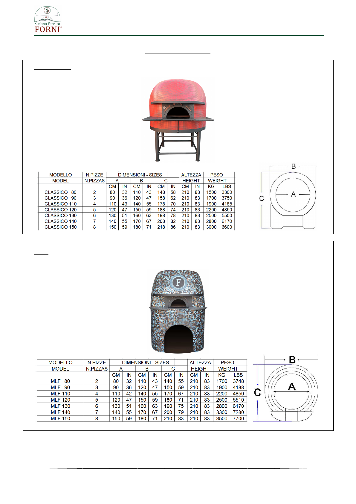
MODELS AND SIZES
CLASSICO
MLF
8
www.stefanoferraraforni.it
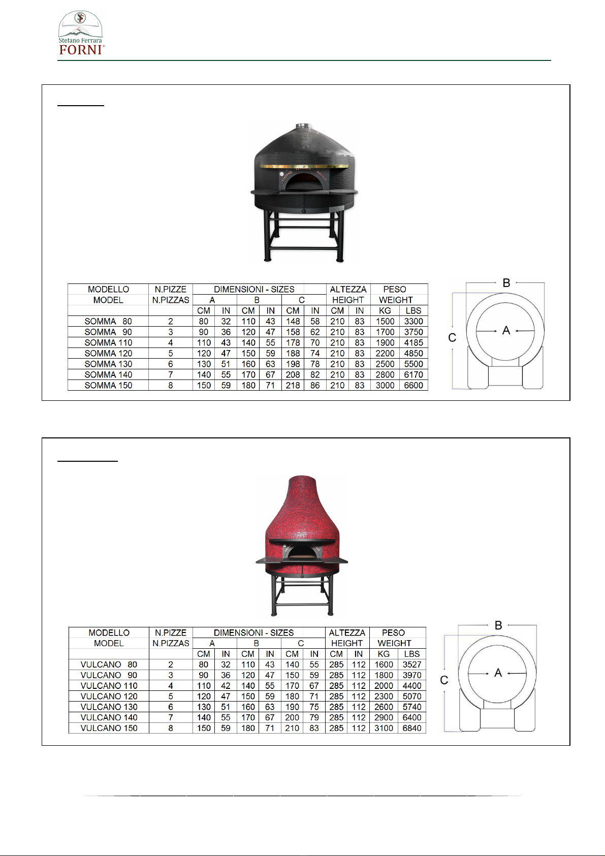
SOMMA
VULCANO

9
www.stefanoferraraforni.it
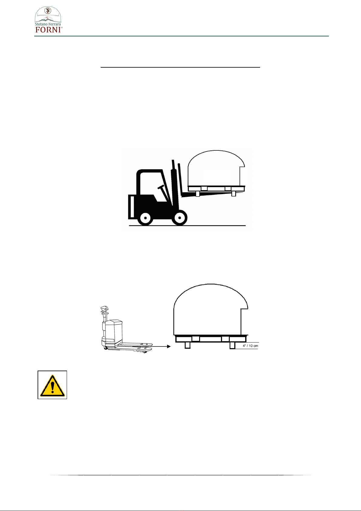
INSTRUCTIONS FOR LIFTING AND MOVING OVEN
FOR OVEN ALREADY INSTALLED ON THE SUPPORT STAND
1- USING A FORKLIFT
Determine if forklift capacity is sufficient to lift oven. (See pag. 7-8 for weights and sizes)
Prior to lifting, make sure the forks are long enough as whole diameter of the oven, if not fork extensions
should be used.
Keep forklift straight. Carefully place forks on the back of the oven through the stand legs
and position under the oven. Slowly lift and move the oven as needed
2- USING A PALLET JACK
Determine if pallet jack capacity is sufficient to lift oven. (See pag. 7-8 for weights and sizes)
Prior to lifting, make sure pallet jack is long enough to reach both horizontal angles at lower end of steel tube
support legs. Place pallet jack on the back of the oven , place the forks between tube steel support legs
under horizontal angles.
Carefully lift oven and move slowly.
10
www.stefanoferraraforni.it
INSTRUCTIONS FOR LIFTING AND MOVING OVEN
FOR OVEN SEPARATED FROM THE SUPPORT STAND
1- USING A FORKLIFT
Determine if forklift capacity is sufficient to lift oven. (See pag. 7-8 for weights and sizes)
Prior to lifting, make sure the forks are long enough as whole diameter of the oven, if not fork extensions
should be used.
Under the oven there are four little steel feet 4” (10 cm) high to permit placing of the forks.
Keep forklift straight. Carefully place forks on the back of the oven through the steel feet and position under
the oven. Slowly lift and move the oven as needed.
2- USING A PALLET JACK
Determine if pallet jack capacity is sufficient to lift oven. (See pag.7- 8 for weights and sizes)
Prior to lifting, make sure the forks are long enough as whole diameter of the oven.
Place pallet jack on the back of the oven, place the forks between the steel feet and position under the oven.
Carefully lift oven and move slowly.
WARNING : STRICTLY FORBIDDEN TO INVERT THE OVEN ALSO ON A SIDE , ONLY
VERTICAL LIFTING IS ALLOWED

11
www.stefanoferraraforni.it
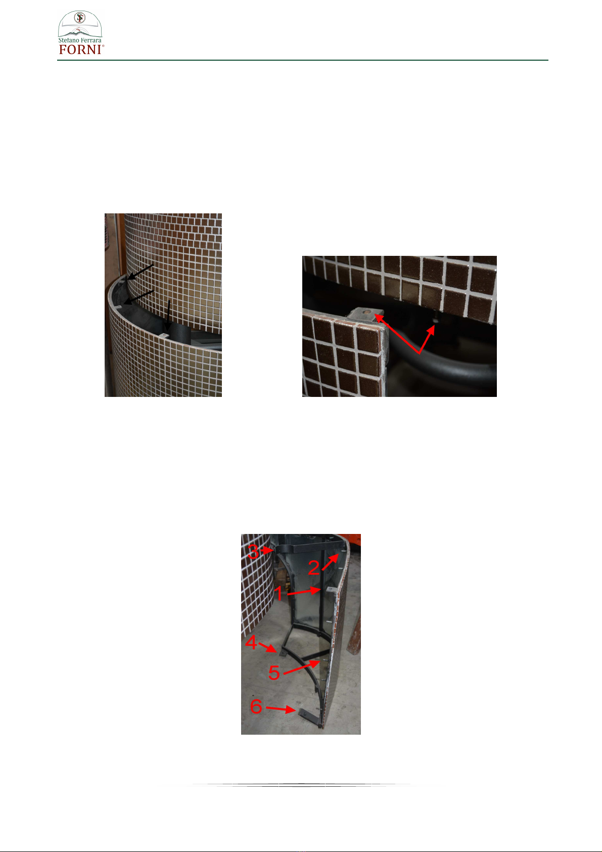
PACKAGING REMOVING AND PLACEMENT OF THE OVEN ON SUPPORT STAND
On the bottom of the crate (front side and back side) there is the required space for insert the forks of the
forklift. (photo 1)
The crate is fixed to two metal brackets placed under the oven (photo 2)
photo 1 photo 2
Once removed the crate for removing the brackets , lifting the oven with a forklift and unscrewing the bolts.
Note: the removed bolts (17 mm. – 0.67 in. hexagonal head screw) will be the same to use for fixing the
oven on the support stand, so preserve them for the next use.
Lifting the oven with a forklift until a higher height than the metallic support stand
Let down carefully for inserting the steel feet placed under the oven into the legs of the support stand
respecting the marked letters :
- Front : A – A
- Back : B – B
Once placed the oven on the support stand to screw the furnished screws (17 mm.- 0.67 in. hexagonal head
screw) in the existing holes on the back of each stand leg.

12
www.stefanoferraraforni.it
INSTALLATION PROCEDURES
1. Be sure to have a sufficient space in the desired location for the oven.
See pag. 7 – 8 for minimum space required according the model
2. Place the oven on appropriate floor able to support the oven weight.
3. Any adjacent combustible floor which
projects in front of the oven opening must
be a minimum of 30 inches (75 cm) away
from each side of the door opening and
36 inches (90 cm.) from the front of the
door opening.
4. It is essential to maintain clearance space
between the oven components and any
combustible material, such as walls and
ceilings.
The oven must have a minimum 10” (25,5
cm.) clearance to combustibles from all
sides and 14" (35,5 cm) clearance to
combustibles from the top.
Warning : Don’t place any type type of
insulation in the required clearance
spaces surrounding the oven
13
www.stefanoferraraforni.it
5. Stand covering installation (optional for models Classico, Somma e Vulcano)
For such working below listed tools are required:
a) Spanner for hexagonal head screws 13 mm. (0.51 in)
b) Spanner for hexagonal head screws 17 mm. (0.67 in)
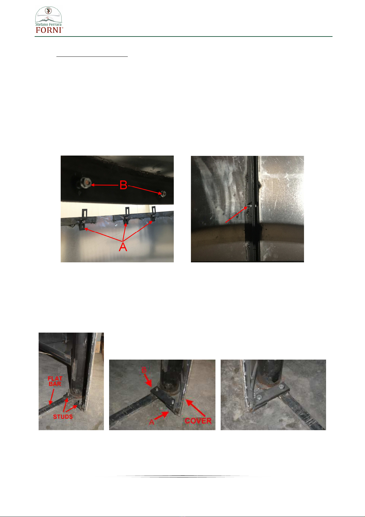
The stand leg covering is provided of some small holed metallic bands (A - photo 1) to fix to the studs
installed at the oven bottom “B” photo 1 with hexagonal nuts 13 mm - 0.51 in
The cover is divided into two parts, place the right part and the left part surrounding the stand legs and join
the two parts by screwing the screws into the holes on the back.(photo 2)
Unscrew the hexagonal nuts from the studs on the oven bottom (B photo 1) , insert each metallic band (A
photo 1) into the correct stud and screw all the nuts
photo 1 photo 2
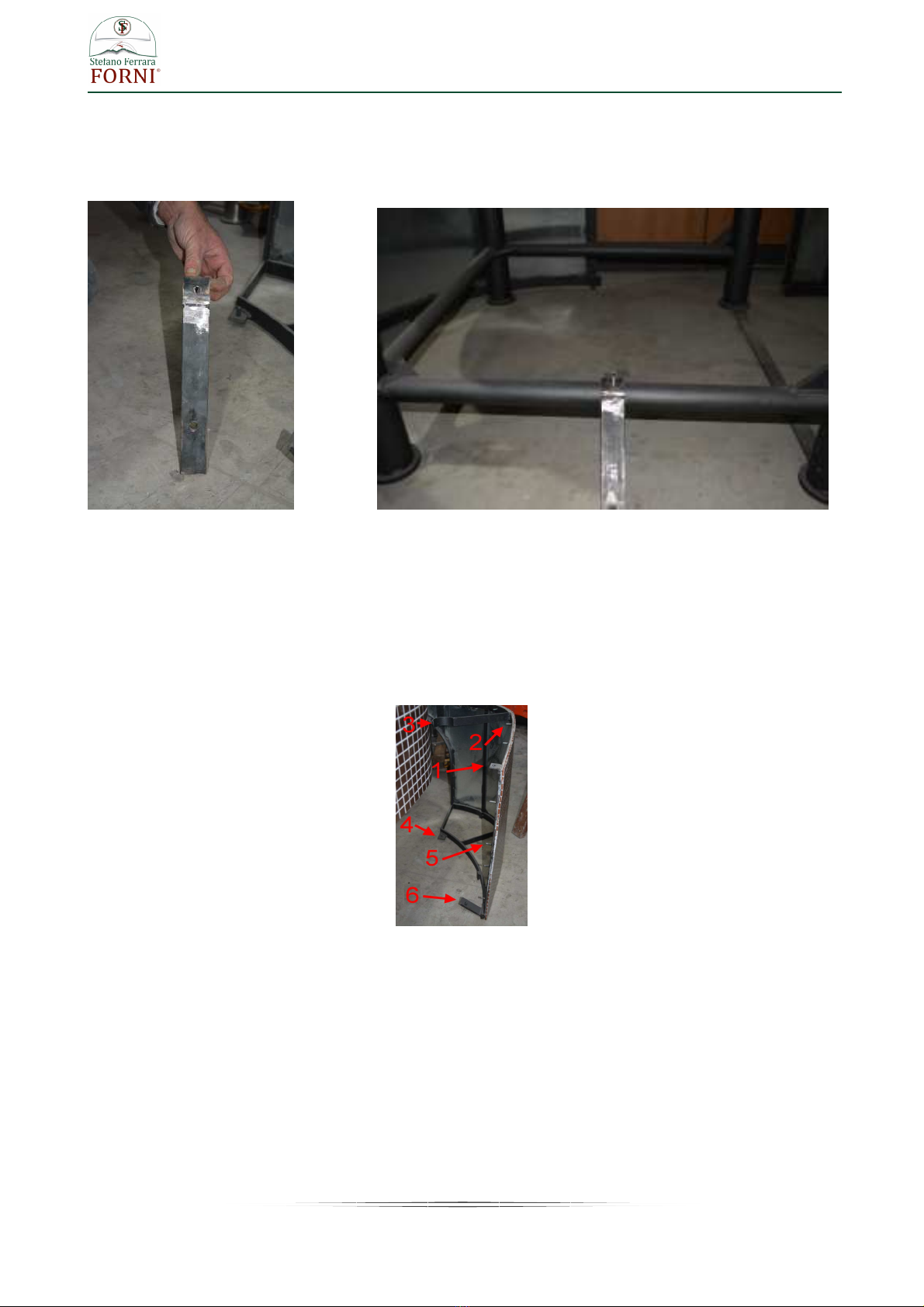
Fasten the front part of the cover to the flat bar of conjunction placed between the two front stand legs
The terminals of the flat bar and the bottom of the frontal cover arch are provided of pre welded studs,
connect these points with the bar ending 45 degree cut .
The 45 degree terminal of the bar (A) is to be fastened to the cover , the terminal with straight ending (B) is
to be fastened to the flat bar . Screw with the provided hexagonal nuts mm. 17 (0.67 in)
photo 3 photo 4 photo 5
On the top and internally to the front arch of the cover two metal fins are welded, insert hexagonal head
screw mm. 13 (0.51 in) and screw well so to get perfect joint of the edges
14
www.stefanoferraraforni.it
5.1 Installation of stand covering for MFL model
For such working below listed tools are required:
a) Spanner for hexagonal head screws 10 mm. (0.40 in)
b) Spanner for hexagonal head screws 13 mm. (0.51 in)
c) Spanner for hexagonal head screws 17 mm. (0.67 in)
Install the back paneling , it’s provided provided of some small holed metallic bands(photo 1) to fix at the
bottom of the oven with the furnished screws (Hex head self-threading screw mm. 10 – 0.40in)
photo 1 photo 2
Place the paneling getting the holes of the metallic bands and the holes of metallic ring underneath the oven
coincide between them (photo 2 previous page), to screw the provided screws. (Hex head self-threading
screw mm. 10 – 0.40 in)
Once installed the back panel install the front panel that is provided of junction points like shown on photo 3
photo 3

15
www.stefanoferraraforni.it
Install the front paneling getting its edges to coincide with the edges of the back panel already assembled
Match the hole of the point “1” (see photo above) with the holes of metallic ring underneath the oven and
screwing the provide screw (hex head self-threading screw mm. 10- 0.40in )
The paneling is provided of some studs on the top and on the sides (see point 2 and 5 photo 3) and the
same studs are welded on the internal side of the perimeter metallic ring underneath the oven and on the
sides of the back paneling.
Put the metallic bands into the studs (photo 4) and screwing the provided hexagonal nuts mm.13 – 0,51in
(photo 5)
photo 4 photo 5
Screw the stirrup with curved end (point “3” photo 6) to the iron tube of the oven stand (photo 7) using hex
head self-threading screw mm. 10 (0.40in)
photo 6 photo 7

16
www.stefanoferraraforni.it
Join the point 4 of the front stand cover (photo 8) to the stand using the metallic stirrup with 45 degrees end .
The stirrup side with 45 degree end must be fixed on the point 4 of the cover (photo 8) the other side with
straight end must be fixed to the prewelded screw on the junction band between the stand legs (photo 10 –
11)
For screwing use the provided hex nuts mm. 17 (0.67in)
photo 8 photo 9
photo 10 photo 11
17
www.stefanoferraraforni.it
Fasten the sides of the oven stand cover to the cross tubes of the same stand with the stirrup showed on the
photo 12
photo 12 photo 13
The curved end of the stirrup must be overlapped on the cross tube of the support stand (photo 13) , get
matched the hole existing on the stirrup and the hole existing on the tube then screwing with the provided
hex screw mm. 10 (0.40in)
The opposite terminal of the stirrup must be overlapped and fastened to the stirrup existing on the stand
cover (point 6 photo below) using the provided hex head 13 mm. (0.51in) screw .
6) Installation of lateral marbles
Lateral marbles come into a separate package
Fasten the marbles on the metallic plate existing at the sides of the oven mouth using some silicone and
waiting complete drying before use them as support shelf
18
www.stefanoferraraforni.it
SANITATION
The ovens are carry a NSF sanitation certification .
They are listed to NSF /ANSI Standard 4 .
This means that the oven interior and the surfaces of the oven which are meant to be left exposed have
been evaluated from the standpoint of sanitation and food safety and are compliant with NSF/ANSI Standard
4.
The ovens provided with the iron stand comply to the NSF requirements just if the stand legs are covered
upon installation.
For covering the stand legs don’t use any combustible material and in case of use of a metal enclosure be
sure the used metal is corrosion resistant .
The ovens provided with the inox steel stand are fully compliant to the NSF requirements so no other work is
requested after installation and the stand legs can be left exposed.
19
www.stefanoferraraforni.it
OVEN VENTING
The venting system of our wood burning ovens is to direct connection, exploiting the natural draught.
The oven employs an integral exhaust hood above the front opening. All flue gases exit the front opening
and drafts into the exhaust hood to be subsequently expelled through a flue pipe (250 mm / 10” in O.D.)
located at the top of the oven. The flue pipe is intended to be connected to a natural draft chimney system
complying with NFPA96 (for USA and Canada)
It’s requested a minimum of 18 “ clearance from combustible material around the flue opening existing on the
top of the oven .
For the flue system we recommend to use a building heating appliance chimney grease duct assembly , (UL
listed for USA and Canada or complying with the local regulations for other countries).
Stainless steel pipes single or twin-walled 250 mm/10 “ in diameter (meant as internal diameter in case of twin
walled pipes) to connect from the chimney connector existing on the top end of the oven up to the desired
place where the smokes will go out.
Installation shall be in accordance with the standard for ventilation control and fire protection of commercial
cooking operations – NFPA 96 (for USA and Canada)
Usually a single wall stainless steel pipe requires minimum of 18” clearance from combustible material , a
double wall pipe requires less clearance so for the right clearance to combustible material please refer to
the company from which you’ll buy the pipes ,as we don’t Know what type of pipes will be installed.
Induct the elements according to the toward of the smokes. The toward of the smokes is understood from
the “ masculine” to the “female” part.
Sew together the elements having care of not damage the seal inserted in the female part. It is advisable to
lubricate the masculine part with a light coat of fat, spray or liquid soap.
Mount and to shut the security wrappers for every junction.
WARNING !
The above information are just some suggestions , for building the flue system is of utmost
importance contact a specialized company and submit your venting plans to local
authorities before proceeding with installations.
The purchaser is responsible of the conformity, correct installation and correct working of
the flue system.

20
www.stefanoferraraforni.it
OVEN CARE DURING FIRST FIRES
As the oven has just been built, it is still damp and the mortar full of water which needs to dry out. Therefore,
it cannot be used immediately for baking but it needs a period of drying out. This can be achieved with one
week (around 8 hours daily) of keeping medium fires just to let it dry and at the same time "cook" both the
bricks and the baking surface.
It's important that you cure your oven slowly, by building a series of central increasingly larger fires. If you
begin building large fires in your oven right way, you could compromise your oven's longevity and ability to
cook well, and even to cause damage.
Place a small amount of wood and kindling on the hearth over a fire-starter block.
Light fire starter. At any time do not use more than four pieces of wood.
Get the oven working for at least 6/8 hours daily proceeding as follows:
Day 1- 2 - 3: The temperature should not exceed 150 °C (302 F).
It could happen that the temperature increases more than 150°C (302 F), this is normal and is due to the
heat retained by the refractory bricks.
During cooking pizzas, bricks absorb heat transferring some humidity to the oven with consequent balancing
of temperature; when no food is placed into the oven, there isn’t this balancing and all the heat is
accumulated and retained by the refractory bricks.
Any way, if the temperature increases more than 150 °C (302 F), get temperature decrease act as follows:
1- Do not add other wood.
If temperature doesn’t decrease:
2- Spread the wood or coals around on the cooking floor for getting less fire.
If also in this case there isn’t any temperature decreasing:
3- Remove some wood from the oven.
WARNING !
Take care during removing wood, wait until when it will be just coal, don't remove wood
with flame. Use a metal shovel for this operation and place the removed wood in a metal
bin with a tightly fitting lid placed on a non-combustible surface, away from any
combustible materials
Day 4: Get the oven work for the entire day at 200°C ( 392 F)
Day 5 through day 7: Increase the temperature of 50°C (122 F) per day
For a better a more sure temperature measurement you can use an infrared thermometer (non provided with
the oven)
During these days of first fires DO NOT CLOSE the door of the oven to the end of the day.
The door opened allows the expulsion of the vapours of the dampness, closing the door the vapours remain
trapped into the oven generating pressures can cause raising of the oven floor.
With the first fires the inside of the oven will become black due to the damp conditions, however after about
two days of baking, the bricks should start to become again clear and that indicates that the oven is finally
ready by to use.
Any cracks on the exterior decoration, normally in the filling between tiles, or on the external plaster for
ovens not provided with finishing of tiles ,it is generally due to the oven stabilization, and it is nothing to worry
about nor it compromise the correct functioning of the same oven.
Note : The week of oven care is sufficient if immediately after this first week the oven continue in working
daily. If for any reason, after the first time of care, the oven is left without building any fire for some days ,
when you will build again the fire you must not start with large fires but it’s good to start with low temperature
increasing it a bit for time .
As more time the oven has been without any fire , much more time you will need for increase of the
temperature
This manual suits for next models
27
Table of contents
Popular Wood Stove manuals by other brands


Ekol
Ekol Clarity 30 Boiler Installation and operating instructions

RIKA
RIKA Cult Plus instruction manual

Harman
Harman Oakwood Wood Stove owner's manual

Regency
Regency F2400M Owners & installation manual

NORFLAM
NORFLAM ARDENTE Installation instructions and operating manual

Dovre
Dovre ASTRO 3CBP Installation instructions and operating manual