Romotop BARACCA User manual


ROMOTOP spol. s r.o., issued on 1 November 2017 Revised Nov 2017 ROMOTOP GmbH, herausgegeben am 01.11.2017 Revision 11/17
D
E
EN
Product sheet under Regulation EU 2015/1186
Supplier's name or trademark: Romotop spol. s r. o.
Supplier's model identifier: BARACCA
The energy efficiency class of the model: A
The direct heat output in (kW): 5,9
The indirect heat output in (kW): 0
The energy efficiency index EEI: 106,1
The useful energy efficiency at nominal heat output (%): 80,1
The useful energy efficiency at minimum load (%): Pass
Special requirements (instalation, maintanance): See instructions
The information in the product sheet of the local space heater shall be provided in the
following order and shall be included in the product brochure or other literature provided
with the product.
EU 2015/1186
Name oder Warenzeichen des Lieferanten: Romotop GmbH
Modellkennung des Lieferanten: BARACCA
Energieeffizienzklasse des Modells: A
D (kW): 5,9
I (kW): 0
Energieeffizienzindex EEI: 106,1
(%): 80,1
Energieeffizienz bei Mindestlast (%): Pass
Besonderen Vorkehrungen (bei der Installation oder Wartung): siehe Anleitung
er andere mit dem Produkt
bereitgestellte Unterlagen aufzunehmen.

ROMOTOP S.A.R.L., 1/17 ROMOTOP spol. s r.o., rilasciato il 01.11.2017 Revisione 11/17
IT
FR
EU 2015/1186
Le nom du fournisseur ou la marque commerciale: Romotop S.A.R.L.
L : BARACCA
L : A
La puissance thermique directe en (kW): 5,9
La puissance thermique indirecte en (kW): 0
L EEI: 106,1
L (%): 80,1
L (%): Pass
fiques (lors de l'assemblage, de la maintenance) : Cf. instructions
-
autre document fourni avec celui-ci.
Scheda prodotto secondo normativa EU 2015/1186
Nome oppure oppure marchio del fornitore: Romotop spol. s r. o.
Codice prodotto del fornitore: BARACCA
classe di efficienza energetica del modello: A
potenza termica diretta in (kW): 5,9
potenza termica indiretta in (kW): 0
indice di efficienza prodotto EEI: 106,1
efficienza del combustibile con potenza termica nominale (%): 80,1
efficienza del combustibile con carico minimo (%): Pass
precauzioni speciali (durante lazione o la manutenzione): Vedi introduzione
da indicare nella seguente successione e da inserire nel depliant o qualsiasi altro catalogo in
riferimento al prodotto.

EN DE FR IT
Product name Produktbezeichnung Nom du produit Nome del prodotto BARACCA 10
Dimensions HxWxD (mm) Abmessungen HxBxT (mm) Dimensions HxLxP (mm) Dimensioni AxLxP (mm) 1462 x 854 x 525
Weight (kg) Gewicht (kg) Poids (kg) Peso (kg) 291
Product name Produktbezeichnung Nom du produit Nome del prodotto BARACCA 11
Dimensions HxWxD (mm) Abmessungen HxBxT (mm) Dimensions HxLxP (mm) Dimensioni AxLxP (mm) 1462 x 854 x 525
Weight (kg) Gewicht (kg) Poids (kg) Peso (kg) 320
Product name Produktbezeichnung Nom du produit Nome del prodotto BARACCA 10 H
Dimensions HxWxD (mm) Abmessungen HxBxT (mm) Dimensions HxLxP (mm) Dimensioni AxLxP (mm) 1749 x 854 x 525
Weight (kg) Gewicht (kg) Poids (kg) Peso (kg) 323
Product name Produktbezeichnung Nom du produit Nome del prodotto BARACCA 11 H
Dimensions HxWxD (mm) Abmessungen HxBxT (mm) Dimensions HxLxP (mm) Dimensioni AxLxP (mm) 1749 x 854 x 525
Weight (kg) Gewicht (kg) Poids (kg) Peso (kg) 354
Completed legislation Abgeschlossene
Gesetzgebung eLegislazione completata -
EN 13 240 / EN 16 510 - 1 / 15a B-VG / DIN + / BImSch V 2 / Ecodesign / Flamme Verte 7* / Aria Pulita 4*
Eco-design (%) (%) -conception (%) Eco-design (%) 70,1
EEI EEI EEI EEI 106,1
Energy Label Energielabel Etichetta energetica A
Prescribed fuel Vorgeschriebener Brennstoff Combustible prescrit Combustibile prescritto Piece wood /
Morceau de bois / Pezzo
di legno
Fuel length (mm) (mm) Longueur de carburant (mm) Lunghezza del carburante
(mm) 180 - 350
Average wood consumption (kg/h)
Durchschnittlicher
Holzverbrauch (kg(h) Consommation de bois moyenne
(kg/h) Consumo medio di legna
(kg/ora) 1,78
Input achieved (kW) Erreichte Leistungsaufnahme
(kW)
Puissance obtenue (kW) Potenza ottenuta (kW) 7,4
Max. allowed wood batch (kg/h) Max. erlaubte Holzzuladung
(kg/h)
Dose massima di legna
consentita (kg/ora) 2,3
Fuel supply interval for the rated
output
Zeitabstand der
Brennstof
Nennleistung
combustible
pour la puissance nominale
Intervallo fornitura
combustibile per potenza
nominale
1. hour, Stunde, heure,
ora
The greatest height of the filling
1/3 of the firebox Hauteur maximale de la charge
1/3 de la hauteur du foyer Altezza massima caricamento
1/3 -
Fuel delivery method Art der Brennstoffbeschickung
combustibile
manually, von Hand,
manuellement,
manualmente
Amount of combustion air (m3/h) Menge an Verbrennungsluft
(m3/h)
(m3/h) (m3/h) 22,6
Nominal heat output (kW) (kW) Puissance nominale (kW) Potenza nominale (kW) 5,9
Total regulated output (kW) Reg. Gesamtleistung (kW) Ren Potenza totale regolata (kW) 3,0 7,7
Exchanger output (kW) Austauscherleistung (kW) Potenza dello scambiatore
(kW)
-
Regulated output of the hot water
exchanger (kW) Reg. Leistung des
Warmwassertauschers (kW) eau chaude (kW)
Potenza regolata dello
scambiatore ad acqua calda
(kW)
-
Filling volume (litres) iter) Volume du remplissage (litres) Volume del riempimento (litri)
-
Max. operating overpressure (kPa)
Max. Betriebsdruck (kPa) Surpression de fonctionnement
max. (kPa) (kPa) -
Efficiency (%) Wirkungsgrad (%) Rendement (%) Efficienza (%) 80,1
Mass flow rate of dry flue gases
(g/s) Massendurchfluss der
trockenen Abgase (g/s) combustion secs (g/s)
Flusso peso combustibile secco
(g/s) 5,6
Dry flue gases mass flow to
calculate the flue path (g/s)
Massendurchfluss von
trockenen Abgasen den
Schornst
einpfad berechnen
(g/s)
ches
(g/s)
Portata massica dei fumi secchi
per calcolare il percorso dei
fumi
(g/s)
7,6
Average flue-gas temperature
Durchschnittliche
Abgastem de combustion ( Temperatura media gas
252
Average flue gas temperature after
Flue pipe
Durchschnittliche
Abgastemperatur hinter dem
de combus
lure
Temperatura media gas
comburenti dietro l
262
Flue draught (Pa) (Pa) (Pa) Tiraggio del camino (Pa) 12
EN DE FR IT
Dust at O2 = 13%
(mg/Nm3) Staub bei O2= 13 %
(mg/Nm3) 2= 13%
(mg/Nm3) Polv 2= 13 %
(mg/Nm3) 24
The concentration of CO
in the flue
gases at O2= 13% (mg/Nm3)
CO Konzentration in den
Abgasen bei O2= 13%
(mg/Nm3)
Concentration en CO dans les
ion pour O2=
13% (mg/Nm3)
Concentrazione CO nei gas
comburenti
2
= 13 % (mg/Nm3) 837
The concentration of CO
in the flue gases
at O
2
= 13% (%)
CO Konzentration
in den Abgasen
bei O
2
= 13% (%)
Concentration en CO dans les
pour O2=
13% (%)
Concentrazione CO
nei gas comburenti
O
2
= 13 % (%) 0,0670
CO2 (%) CO2 (%) CO2 (%) CO2 (%) 9,19
OGC - 02=13% (mg/m3) OGC - 02=13% (mg/m3) OGC - 02=13% (mg/m3) OGC - 02=13% (mg/m3) 25
NOx - 02=13% (mg/m3) NOx - 02=13% (mg/m3) NOx - 02=13% (mg/m3) NOx - 02=13% (mg/m3) 100
Connection height for rear
installation (mm) (mm) Hauteur de raccordement pour
(mm) Altezza di collegamento per
l'installazione posteriore (mm)
1352
Flue pipe diameter (mm) Rauchabfuhrdurchmesser (mm)
(mm) Diametro del condotto fumi
(mm) 150
Flue throat (mm) Flue Hals (mm) Flue la gorge (mm) Fumi gola (mm) 150
CAI diameter (mm) CPV-Durchmesser (mm) Diametro ACA (mm) 125
Dimensions of t
he combustion
chamber HxWxD
(mm)
Feuerraum HxBxT
(mm) Dimensions de la chambre de
combustion HxLxP
(mm)
Dimensioni della camera di
combustione AxLxP
(mm)
340 x 506 x 210
Dimensions of the furnace
door HxWxD
(mm)
HxBxT
(mm) Dimensions de la porte du four
HxLxP
(mm)
Dimensioni della porta del
forno AxLxP
(mm)
-
Min. cross section of convect air
inlet for nominal output
(cm2)
Min. Querschnitt der
Konvektionsluftzufuhr f. die
Nennleistung
(cm2)
i r de
convection pour rendement
nominal
(cm2)
Sezione minima
de
convezione per la potenza
nominale (cm2)
-
Min. cross section of convect air
outlet for nominal output
(cm2)
Min. Querschnitt des
Konvektionsluftausgangs f.
die
Nennleistung (cm2)
convection pour rendement
nominal
(cm2)
aria di convezione per la
potenza nominale (cm2) -
Door design
(Right=1 / Left=2 / Sliding =3)
(Rechts=1/Links=2/Schieben
=3)
ation de la porte (
Droite=1 /
Gauche=2 / Coulissant = 3)
Versione dello sportello
(Destra=1 / Sinistra=2 /
estraibile = 3) 2
Back door design (No=0 /
Right=1
/ Left=2 / Sliding =3)
ign (Nein=0 /
Rechts=1 / Links=2 / Schieben
= 3)
Concept
(Non =0 / Droite=1 / Gauche=2 /
Coulissant = 3)
Design della porta posteriore
(No=0 / Destra=1 / Sinistra=2
/
estraibile = 3) 0
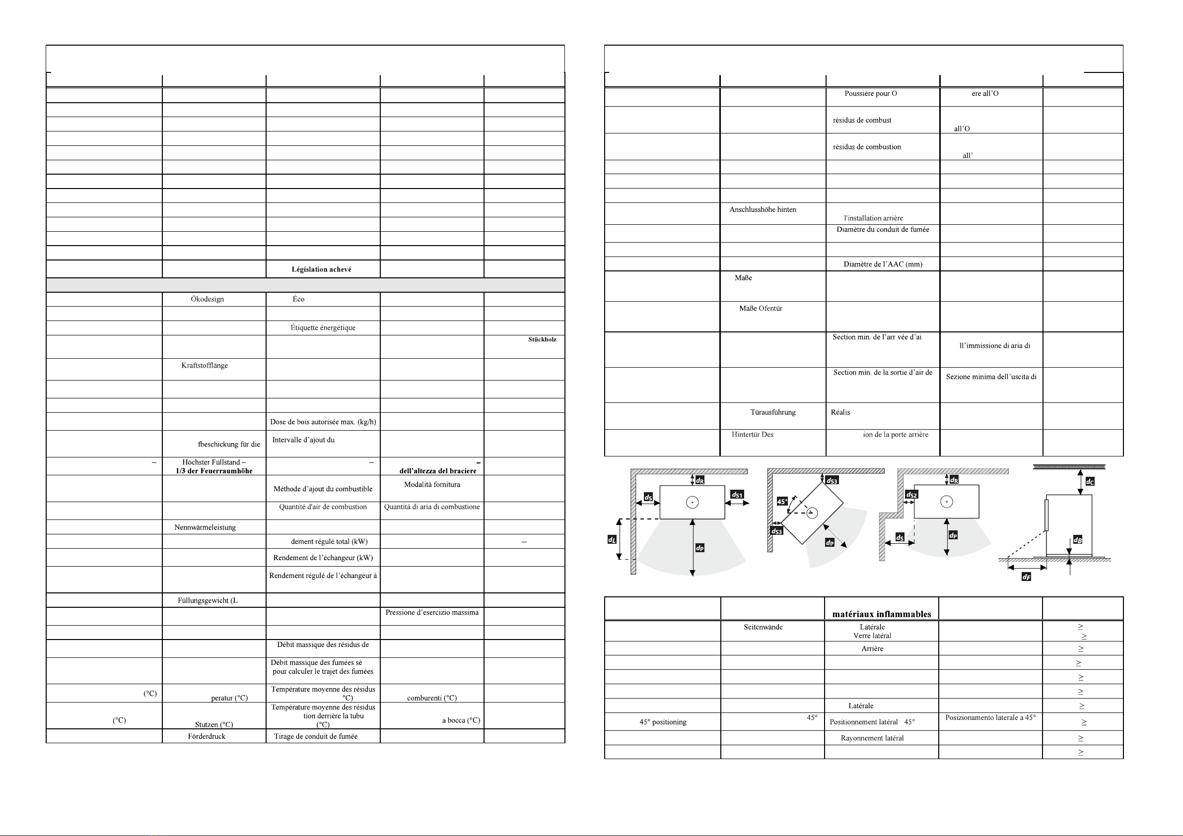
Distance from flammable
materials Abstand von
Brennstoffen Eloignement des Distanza da materiali
infiammabili
Side (mm)
Side with glass (mm) (mm)
Seitenglas (mm) (mm)
(mm) Laterali (mm)
Vetro laterale (mm) dS300
dS1 ---
Back (mm) Hinterwand (mm) (mm) Posteriore (mm) dR100
Front (mm) Frontwand (mm) Frontale (mm) Anteriore (mm) dP1200
From the ceiling (mm) Von der Decke (mm) Du plafond (mm) Dal soffitto (mm) dC750
Front to floor (mm) Front zum Boden (mm) De l'avant au sol (mm) Da fronte a terra (mm) dF670
Side - niche (mm) Seite - Nische (mm) - niche (mm) Laterali - nicchia (mm) dS2 100
Side - (mm) Seitliche Positionierung -
(mm) - (mm)
(mm) dS3 ---
Side radiation (mm) Seitliche Strahlung (mm) (mm) Radiazione laterale (mm) dL500
From the floor (mm) Von dem Boden (mm) Depuis le sol (mm) Dal pavimento (mm) dB195
Technical Sheet, Technisches Datenblatt, Fiche technique, Scheda tecnica Technical Sheet, Technisches Datenblatt, Fiche technique, Scheda tecnica

Supplied accessories Mitgel
Accessoires fournis Accessori forniti
Protective glove
yes=1 / no=2 Schutzhandschuh
ja=1 / nein=2 Gant de protection
oui=1 / non=2 Guanto protettivo
1
Hook to open the ashtray
yes=1 / no=2 Haken um den Aschenbecher
fnen ja=1 / nein=2 Crochet pour ouvrir le cendrier
oui=1 / non=2 Agganciare per aprire il
posacenere 2
Ashtray
yes=1 / no=2 Aschenbecher
ja=1 / nein=2 Cendrier
oui=1 / non=2 Portacenere 1
Air regulation, Luftregulierung, R Regolazione aria
Chamotte chamber, Schamottkammer, e
Dimension sketch, Croquis des dimensions, Dimensioni ingombro
- BARACCA 10
Description EN: Beschreibung DE: Description FR : Descrizione IT:
A 150 mm Flue throat Flue Hals Flue la gorge Fumi gola
B 125 mm CAI inlet CPV-Eingang Ingresso ACA
C Air regulation Luftregulierung R Regolazione aria
EN Procedure for exchange of chamottes:
1. Pull out the ceiling fireclay plat 1
2. Pull out the side fireclay plates - 2
3. Pull out the bottom fireclay plates - 3
4. Pull out the rear fireclay plates - 4
5. Use the reverse order for re-assembly
Note: Cracks in the chamotte do not have any effect on the
combustion and service life of the stove. The chamottes
should not remain crumbled to the metal for prolonged
periods of time.
Warning: When stoking logs, make sure they do not hit the
chamottes hard to prevent damage!
DE -
1. Decken Schamottplatte herausziehen 1
2. Seitenschamottplatten herausziehen - 2
3. Untere Schamottplatten herausziehen - 3
4. Hintere Schamottplatten herausziehen - 4
5. Wiedereinbau in umgekehrter Reihenfolge
Bemerkung: Ein einzelner Sprung hat keinen Einfluss auf das
Brennverhalten sowie die Haltbarkeit des Ofens Die
Scham
he
Hinweis: Beim Zulegen mit den Holzscheiten nicht heftig an
FR - :
1. Sortir le plaque en 1
2. S ales - 2
3. - 3
4. - 4
5. M
Remarque :
sur la combustio
Les chamottes ne devraie
a
Avertissement : Rajoutez les
frappent pas brusquement les chamottes, cela les abimerait !
IT Procedimento per la sostituzione dello chamotte
1. Estrarre gli chamotte superiore 1
2. Estrarre gli chamotte laterali - 2
3. Estrarre gli chamotte sul fondo - 3
4. Estrarre gli chamotte posteriori - 4
5.
Nota: Le eventuali screpolature dello chamotte non hanno alcuna
influenza stufa. Si
consiglia di non lasciare gli chamotte a lungo sgretolati fino alla
lamiera.
Avvertimento: I pezzi di legno vanno applicati in modo tale da
non farli urtare bruscamente contro lo chamotte, per evitare
conseguenti danneggiamenti!

Dimension sketch, Croquis des dimensions, Dimensioni ingombro
- BARACCA 11
Description EN: Beschreibung DE: Description FR : Descrizione IT:
A 150 mm Flue throat Flue Hals Flue la gorge Fumi gola
B 125 mm CAI inlet CPV-Eingang Ingresso ACA
C Air regulation Luftregulierung R Regolazione aria
Dimension sketch, Croquis des dimensions, Dimensioni ingombro
- BARACCA 10 H
Description EN: Beschreibung DE: Description FR : Descrizione IT:
A 150 mm Flue throat Flue Hals Flue la gorge Fumi gola
B 125 mm CAI inlet CPV-Eingang Ingresso ACA
C Air regulation Luftregulierung R Regolazione aria

Dimension sketch, Croquis des dimensions, Dimensioni ingombro
- BARACCA 11 H
Description EN: Beschreibung DE: Description FR : Descrizione IT:
A 150 mm Flue throat Flue Hals Flue la gorge Fumi gola
B 125 mm CAI inlet CPV-Eingang Ingresso ACA
C Air regulation Luftregulierung R Regolazione aria

EN General installation and operation manual
for Romotop spol. s r.o. fireplace stoves
- valid in general for all types of fireplace stoves manufactured by Romotop spol. s r.o.
The attached technical sheet lists detailed technical data for each type of fireplace stove.
Installation of fireplace stoves may only be done by reseller authorized by Romotop spol. s r. o. .
The fireplace stoves may only be operated in accordance with this manual!
No unauthorized changes may be performed on the fireplace stoves!
1. Introduction
2. Technical description
3. Safety regulations
3.1 Safe distances
3.1.1 Safe distance of fireplace stoves from flammable materials
3.1.2 Safe distance of flue pipes from flammable materials and building constructions
3.2 Floor protection
3.3 Chimney fire prevention measures
4. Assembly regulations
4.1 General
4.2 Chimney connection
5. Operation manual
5.1 Fuel
5.2 Starting the fireplace stove for the first time
5.3 Kindling and firing
5.4 Stoking fuel
5.5 Operation during the transition period
5.6 Ash removal
6. Cleaning and maintenance
6.1 Cleaning the glass
6.2 Cleaning the fireplace stoves / disassembly of chamotte
6.3 Cleaning the chimney
7. Disposal of covers and the discarded product
8. Warranty
1. Introduction
Thank you for purchasing our fireplace stove and congratulations for becoming the owners of top-notch
fireplace stoves by Romotop spol. s.r.o., one of the forefront European manufacturers of fireplace heaters.
Our fireplace stoves can function as additional heating to augment the atmosphere of your home or
recreational building or as the main source of environmentally-friendly heating with high heat output, dust-free
operation and perfect combustion. All fireplace heaters produced by our company are tested in accordance with
240/2002+A2/2005.
Please read through the manual and technical sheet thoroughly. The user is obliged to get properly acquainted
with proper installation and operation of this device with regards to its safe operation. Please keep the manual
and technical sheet so that you can brush up all the information necessary for the correct operation of your
fireplace stove before each heating season.
We only provide a warranty on our products if all the instructions listed in this operation manual are adhered to.
2. Technical description
Fireplace stoves are intended for installation into various interiors (apartments, recreation buildings,
restaurants). Romotop spol. s r.o. fireplace stoves are manufactured from quality construction materials cast
metal, CORTEN steel and quality construction and fittings steel, with stressed parts made of HARDOX steel.
The surface of steel constructions is protected by a refractory opaque paint. Refractory paints are not anti-
corrosive. The combustion chamber of full-plate fireplace stoves is padded by removable chamotte desks, which
are not connected by any paste material to prevent damage by heat dilatation. The combustion chamber can be
firmly closed by doors with special heat-resistant glass. The glass not only increases the aesthetics of the
flickering flames, but also facilitates pleasant heat radiation. The glass also prevents the sparks from the burning
wood and smoke from entering the room. The floor of the combustion chamber is usually equipped with a
removable cast-iron grate. Usually, a barrier, or alternatively a sheet metal or ceramic mould, is placed in front
of the grate to prevent the fuel falling and sliding onto the doors (front window). Grate fireplaces include room
for an ashpan under the grate. Some types allow custom-configuration of the flue pipe throat for top- or back-
side exhaustion. The fireplace stoves are manufactured with dual coating. The area between the coatings is used
for air heating. The upper part of the outer coating includes vents for the heated air. The outer coating may
include ceramics or stone to highlight the design and improve the heat accumulation properties of the fireplace
stove. Some types of fireplace stoves have adapted the double-coating construction to heat warm service water
with an optional connection to the standard heating system. These fireplace stoves may be equipped with a
cooling loop to avoid overheating in case of power outages.
Fireplace stoves equipped with a separate intake of primary and secondary combustion air include the
appropriate control elements. The primary air is taken to the burning fuel (usually through the ashpan and grate)
and is used for primary combustion. The secondary air supports combustion of residual combustible gases in the
exhaust, increasing the output of the heater and significantly reduces the amount of pollutants escaping into the
atmosphere. The secondary air is mostly taken to the area above the burning fuel. Its presence causes the cold
air to roll around the inner side of the front glass. This process simultaneously prevents the blackening of the
front glass. The secondary air also participates in the primary combustion process when the primary air intake is
partially or completely sealed. Keep the primary air intake fully open at the beginning of the combustion
process, when the chimney draft is still weak. After the chimney heats up, you can partially or even completely
close the primary air intake, based on the target output of the fireplace stove. It is also possible to reduce the
fueling or limit the chimney draft by attaching a smoke shutter (a manual shutter in the flue pipe limiting the air
intake to at most 75%) to reduce the output of the fireplace stove. This is recommended especially for chimney
draft around and above 20Pa. The secondary damper is intended to fully close the stove when it is not in
operation. The fireplace and ashpan covers must always be closed except for starting operation, adding fuel and
removing solid combustion remnants to prevent exhausts entering the room.
Some fireplace stoves are equipped with a heat accumulation exchanger, improving the efficiency of the
fireplace stoves and maximally utilizing the fuel energy.

Some fireplace stoves are manufactured with a External air intake (EAI). This allows air to flow into the
combustion chamber in the fireplace stove from the exterior*, halls, technical rooms etc. Fireplace stoves with a
EAI are not dependant on the amount of air in the heated area. Thus, they not only contribute to a pleasant
atmosphere in your home, but also reduce energy expenses (since heated air already in the room is not
consumed). When installing the External air intake (EAI) outlet to the wall, it is important to make sure that the
pipe runs at a negative angle from the product. EAI lines must be isolated.
Fireplace stoves with EAI are very suitable for installation into low-energy houses. It is also possible to
equip the heating system of some fireplace stoves with EAI with electronic combustion regulation to increase
comfort. This can additionally increase the combustion process and stoking intervals, increase operation safety
and prevent uneconomic heating and over-heating of fireplace stoves (the shutter of the central air intake is
controlled by a control unit and servomotor in relation to the current combustion phase and output exhaust
temperature).
Warning: The fireplace stoves are not manufactured to provide continual heating and are intended for
periodic interrupted operation, mostly due to the need to empty the ashpan when the ash has cooled down.
*When connecting to an external air intake (from the outside), it is recommended to install double-acting flap
with a silicone cuff with possibility of closing air intake. This will prevent corrosion due to moisture
condensation when the product is not in use. The warranty does not cover damage caused by corrosion!
Attention, care must be taken to ensure that the damper is always open when the product is in operation!
3. Safety regulations
The fireplace stoves may be used in normal environments in accordance with -1 ed.2/2009. In
case of change of environment that could cause a temporary danger of fire or explosion (e.g. gluing linoleum,
PVC, working with paints, etc), the fireplace stove must be put out of operation in time, i.e. before the
occurrence of the dangerous situation. Furthermore, the fireplace stoves can be used only after the room is
thoroughly aired, preferably by wind draft.
A supply of sufficient amount of combustion air and room ventilation air must be ensured when the fireplace
stoves are in operation, especially with another heat device running simultaneously (approx. 8to 15 m3for
burning 1 kg of fuel)! When doors and windows are tightly sealed, this might not be the case! This is solved by
a CAI connected into a separate room. The regulation grate for combustion, ventilation and heating air must not
be obstructed. When stoking fuel, always open the door very slowly. You will prevent smoke and ash from
escaping into the room. The fireplace stoves require casual attendance and inspection.
Flammable fuels must not be used for stoking or heating! In addition, burning plastic material of any kind,
wood materials with various chemical bonding agents (chipboards, etc) or unsorted domestic waste with
remaining plastics is prohibited by law no. 201/2012.
Make sure to prevent children from handling the fireplace stoves during heating. The fireplace stove
may only be operated by an adult person!
During heating all handles and knobs must be operated using a pair of tongs, hook or by a hand protected by
a glove (pot-holder) - there's a danger of burns! Objects made from flammable materials that could be set on fire
must not be stored on the fireplace stoves during operation and while hot. Please pay special attention when
handling the ashpan and when removing hot ash due to danger of burns! The hot ash must not get in contact
with flammable objects - e.g. when throwing in communal waste containers.
When the fireplace stove is used only seasonally and with unfavorable draft or weather conditions, special
attention must be paid when putting the stove into operation. When the fireplace stove is not in operation for a
longer period of time, the flue ways must be checked for obstructions before further operation.
The appropriate safety regulations for fireplace stove operation and installation must be adhered to in
3.1 Safe distance:
3.1.1 Safe distance of fireplace stoves from flammable materials
When installing the fireplace stove in a place containing flammable materials belonging to class B, C and D,
the required safe distance in accordance with is 80cm from doors and 20cm in other
directions, unless otherwise specified by the manufacturer refer to the Technical sheet and the Name plate.
When installing the fireplace stove in a place containing flammable materials belonging to class E or F, the
distance must be doubled. Information on the degree of flammability of certain building materials is listed in
501-1+A1/2010 and . When the prescribed safe distance of the heater from the
flammable materials cannot be kept, it is necessary to use a protective screen according to
1008/1997.
Building materials sorted based on their reactivity with fire
A1 or A2
B
C
D
E or F
3.1.2 Safe distance of chimneys from flammable materials and building constructions
The safe distance from door case covers and similarly located building constructions from flammable
materials and from pipeline installation including its insulation is at least 20cm. The safe distance from other
flammable parts of the building construction at least 40cm according to . This includes
building materials belonging to classes B, C and D as defined in N EN 13501-1+A1/2010 (see table no.1)
The same applies for walls and especially ceilings with plaster on a flammable surface, e.g. crates, planks, etc.!
When the prescribed safe distances cannot be kept, the danger of fire must be prevented through construction
solutions, non-flammable applications, heat-resistant insulations or protection screens.

3.2 Floor protection
Unless the fireplace stove is installed on a 100% non-flammable floor, it is necessary to place the stove on a
non-flammable insulation mat, e.g. metal plate (at least 2mm thick), ceramics, hardened glass, stone, in order to
prevent the flammable floor to exceed a temperature of during operation in accordance with
4230/2014.
According to 5.1.3.3 of the insulation mat must exceed the fireplace by at least
-30cm in the vertical direction from the stove stoking door.
-10cm in the horizontal direction from the stove stoking door.
Items made of flammable materials may not be placed on top of or at a less-than-safe distance from the
fireplace stoves.
3.3 Chimney fire prevention measures:
Ordinary operation, especially with humid fuel, leads to the settling of ash and tar in the chimney. Neglecting
regular checking and cleaning of the chimney in accordance with the government regulation no. 34/2016
Coll. from 22st January 2016 increases the danger of fire.
In case of ash or tar catching fire in the chimney, please follow this procedure:
- do not under any circumstances extinguish the fire with water as it would create an abnormal amount of
steam and subsequently rip the chimney open
- if possible, the combustion chamber should be covered with dry sand, which will extinguish the fire
- close all intakes of air for combustion; if possible, cover the chimney. However, the smoke must not
accumulate back in the house
- contact your nearest fire fighting brigade to assess the situation and the necessity to report it as a fire
fighting emergency
- do not leave the house until the chimney is burned up; regularly check the chimney temperature and the
course of combustion
- contact a chimney service before starting a new fire in the stove to assess the state of the chimney and also
contact the manufacturer of the fireplace stove for inspection.
4. Assembly regulations
Warning: All local regulations, including regulations concerning national and European standards for
this type of appliances, must be adhered to:
- Fireplaces with open and closable furnace
- Built-in heating appliances and open fire inserts for solid fuel
- Room heaters fired by solid fuel
- Chimneys and connecting flue pipes - Design, construction and installation of
heating appliances
- Chimneys General requirements
-1+A1/2010 - Fire classification of construction products and building elements
- Fire protection of heating appliances
Decree No. 268/2011 Coll. - Technical conditions of fire protection of buildings
4.1 General
The fireplace stoves must be installed on a floor with an adequate bearing capacity. If the existing
arrangement does not meet this basic requirement, necessary steps must be taken (e.g. using a mat for
distributing the load). Make sure that there is enough space for cleaning the fireplace stove, connecting flue
pipes and the chimney unless the chimney can be cleaned from other place, e.g. a roof or through doors
designed for this purpose.
4.2 Chimney connection
Before assembling the closed fireplace stove it is necessary to calculate that the chimney construction will be
suitable for the installed fireplace stove nominal output as far as design, vent size and effective height are
concerned.
A suitable chimney (minimum profile, chimney draft, tightness, etc.) is a basic condition for the proper
functioning of the fireplace stoves. You should therefore contact a chimney sweeper before installing the
fireplace stove. Chimney values are included in the attached technical sheet. A smoke shutter or a draft regulator
should be installed for chimneys with too strong a draft. Such a draft can cause problems during operation, e.g.
intensive burning, high fuel consumption and can also lead to permanent damage of the fireplace stove.
The minimum effective height of the chimney for exhaust gas from the stove is 5m (measured from the hoop
to the chimney mouth). The chimney entry must be equipped with a chimney hoop. Consult the vent connection
with the vent manufacturer. The vents must lead at least 5cm below the lower ceiling. Connect the flue mouth
with the chimney in the shortest possible way so that the flue length is at most 1/4 of the effective height of the
chimney (i.e. 1.5m). Connect the flue tube and the knee together with an overlap in such a way that the
connections always agree with the exhaust gas flow, or abut using the connection rings. If the connecting piece
passes through construction elements with flammable materials, it is necessary to use protective measures in
accordance with . The norm states that the flue pipe needs to rise to the vents in the direction
of exhaust flow with a degree of at least . The tightness and firmness of the joints is crucial. The chimney and
stove connection must adhere to SN 73 4201/2016 ed.2. The casing of the chimney must not exceed a
temperature of during the highest operation temperature of the stove. The cross section of the flue pipe
vents must not be larger than the cross section of the chimney vent and it must not narrow down in the direction
of the chimney. If calculations show that the cross section of the flue pipe and chimney vent could be smaller
than the cross section of the exhaust throat of the fireplace stove, the cross section of the flue pipes will be
lowered immediately behind the exhaust throat of the fireplace stove, either gradually or at a discrete point. The
flexible flue pipe from the materials in accordance with table A.1. may only used in places where it may be
checked in accordance with 1/2016 ed.2, and unless the flue pipe leads through an open air its
checkability must be ensured in accordance with . A vertical flue pipe may only be
used in the cases listed in .
The fireplace stove may be connected to a shared vent with a gas appliance for multi-layer chimneys in
accordance with 16 ed.2.
Leakage of water into the product when using a vertical flue with a chimney function is not a reason
for a complaint!
When installing ROMOTOP spol. s r.o. fireplace stoves in the FRG in compliance with article 6.2.2 of the
DIN 18 896 norm, the fireplace stoves can be connected to a shared chimney.
5. Operation manual
5.1 Fuel
It is only allowed to burn wood in fireplace stoves in accordance with law No. 201/2012 Coll.. To reach the
nominal parameters of the heater, we recommend using dry logs with a diameter of 5-8 cm and length of 20-30
cm and with a humidity below 20% (ideally 10%). Oven wood and chopped pieces of wood should be used
only when starting the fire. Recommended humidity can be obtained by storing the chopped logs for at least two
years in a ventilated shelter.

The fireplace stove should be heated to a nominal output stated in the technical sheet, i.e. the burning of a
given amount of allowed fuel per 1 hour. Long-term excessive output could damage the fireplace stove.
Never use flammable fluids, coke, coal or any of the following types of waste as fuel: chipboards,
plastics, plastic bags, soaked wood or wood-shavings, saw-dust or pellets!
!!!Burning of the abovementioned material not only highly pollutes our environment but also damages
the fireplace stove and the chimney!!!
5.2 Starting the fireplace stove for the first time
Before the first use all remaining stickers must be removed, all accessories must be taken out of the ashpan or
fireplace and the same applies for the transport safety pins. All plastic cover plugs on threaded connections
are not functional, they are only used for transport. Check that bulk shutters for directing the draft, chamotte
tiles and the barrier are set correctly (as they might have slipped from their correct positions during transport or
installation). Repair any defects you might find in setting, otherwise the proper functioning of the heater is
endangered. After setting the fireplace stove, connecting it to the chimney and, if need be, connecting the
exchanger to the warm-water set and filling it with a heat-carrying medium, start heating slowly and continue
for at least two hour. Leave the stoves and ashpan doors open (approx 10-20mm) before and during the first
heating in order to prevent the sealing material to mix with the paint. The fireplace surface is covered with heat-
resistant paint. During the first heating, after becoming temporarily soft, the paint will eventually become
hardened. During the soft phase the paint surface is more vulnerable to being damaged by a hand or other object.
mall
amount of fuel with a lower temperature. The entire process of first putting the product into operation is
done with the maximum opening of the air supply. Therefore, the first two loadings of fuel should
correspond to the bottom limit of the recommended fuel batch ( ). All
materials must get used to the heat load. You will prevent cracks in chamotte bricks, damage of the paint or
deformation of the insert materials by a careful first heating. Following loadings of fuel should then
correspond to the maximum allowed fuel batch (
hours. Thanks to these high temperatures (maximum performance), the paint is reinforced. Hardening of
the paint on the fireplace stove might be accompanied by a temporary smell, which will disappear after a while.
Make sure the room is properly aired when burning the paint. Furthermore, ensure that no small
animals or birds are present in the room containing paint exhausts. We also recommend turning off
aquariums air intakes during the first heating.
5.3 Kindling and firing
1. Fireplace stoves with grate - first put crumpled paper into the chamber and then lay chopped wood on it.
You can also used the solid fire-starter to start the fire. After starting fire, let it burn freely with all air regulation
elements open. It is forbidden to use flammable liquid (oil, petroleum, etc.) for starting fire! After the fire
begins to burn and the draft is strong enough, bigger logs might be added without the danger of smoke. Continue
stoking the amount of fuel determined based on the nominal output of the fireplace stove.
2. Fireplace stoves without grate - only secondary air is used for burning; therefore wood logs need to be
stoked first, then chopped wood and finally small cuttings and paper. After starting fire, let it burn freely with all
air regulation elements open. It is forbidden to use flammable liquid (oil, petroleum, etc.) for starting fire!
After the fire begins to burn and the draft is strong enough, bigger logs might be added without the danger of
smoke. Stoke no more than the amount of fuel determined based on the nominal output of the fireplace stove.
Fuel consumption is always stated in the technical sheet. Burning intensity is regulated by air intake controls
or, if a smoke shutter is installed, by limiting the draft in the chimney. Larger amount of fuel or a strong draft
and air take might cause overheating and damage of the fireplace stove. Too weak draft leads to glass
blackening or to a smoke escaping into the room when opening the door and stoking fuel.
Warning: Fireplace doors must always be closed, with the exception of the first heating, stoking fuel and
removing ash. When the fireplace stove is not in operation for a longer period of time, it is necessary to check
that the flue pipes, chimney and combustion chamber are clear. In general, the heating up and cooling of the
fireplace insert is accompanied by a specific sound; this is intended.
5.4 Stoking fuel
In order to prevent smoke escaping into the room when stoking fuel, please follow the following procedure:
Approximately 5 or 10 seconds before opening the fireplace doors open the air intake regulators and then only
slightly open the stoking doors, wait for few seconds for the exhaust gas to get sucked into the chimney and only
then fully open the door. When opening the stoking door, a special attention must be paid to the danger of hot
fire-brands falling out. After stocking fuel, close the door again. After the fuel starts burning (with clear fire),
return the regulator back to its original position. The amount of stoked fuel should correspond to an hourly
consumption value for the concrete fireplace stove (see the technical sheet). Overheating can permanently
damage the fireplace stove construction.
Warning: To prevent exhaust gas escaping into the room during stoking add fuel after its burning down on
the glowing base.
5.5 Operation during the transition period
The chimney draft (sucking exhaust gas from the fireplace stove) might be weaker during the transition
period, i.e. when the outside temperature is higher than , during rainy and humid days or during gust airs.
During this period the fireplace stove should be operated with the minimum possible fuel so that the fire, as well
as the chimney draft could be improved by opening the air intakes.
Tip: During this period a so-called atmospheric plug can be created in the chimney mouth due to the draft
conditions. The plug can caused smoke escaping into the room when lighting fuel. We recommend letting a
piece of paper burn down preferably in the upper part of the combustion chamber before lighting the kindling.
This seemingly negligible smoke is enough to break through the atmospheric plug. Afterwards you can freely
light paper (or solid fire-starter) and be sure that even a humid chimney is clear.
In this period it is also possible to use the same lighting method as for the fireplace stoves without grate (with
no ashpan).
5.6 Ash removal
Make sure that the ashpan is cleaned when being half full in order to prevent the ash reaching too close to the
grate and thus damaging it. At the same time the ash would block the intake of air required for burning.
Removing ash from the ashpan should be carried out when the fireplace stove is cold and preferably ready for
the next heating. A vacuum cleaner designed for cleaning ash with a filter for small filth can be also used for
cleaning the cold ashpans or heater without ashpans. Ash from burnt wood can be used for composts or
fertilizing. Store the ash in closed non-flammable containers.
Warning: Make sure that the ash does not contain any glowing remains of wood that could cause fire in the
waste container.

Warning: For some fireplace stove types the ashpan is located in a basin under the grate and cannot be
removed from the side. The ashpan can be removed only when the heater is cold and not in operation. The
ashpan is accessible after lifting the grate.
Be careful when removing hot ash!
6. Cleaning and maintenance
Your fireplace stove is a high-quality product and no significant defects will appear during normal operation.
Fireplace stove and flue system need to be checked and cleaned regularly and thoroughly before and after the
heating season.
For cleaning and maintenance work you always have to make sure that the stove is not warm!
The surface of the fireplace stove is protected by flame-retardant coating. The flame-retardant coating
is not anticorrosive. Avoid direct contact with water, other cleaning agents, abrasives or solvents.
Clean the surfaces of the fireplace stove with a soft, dry cloth!
6.1 Cleaning the glass
The cleanliness of the window is influenced not only by the using of suitable fuel, providing sufficient air
intake and chimney draft but also by the method of operating the fireplace stove. In this respect we recommend
stoking only one layer of fuel and distributing the fuel as evenly as possible and as far from the glass as
possible. If the glass becomes dirty, try increasing the burning intensity by opening the air intake and the glass
will clean itself.
Sooty windows can be cleaned in cold state using newspapers or wet cloth dipped in wood ash. Usually
also liquid cleaning agents are used for cleaning the stove window. But these may in some cases, depending on
the composition of the cleaning agent and its interaction with combustion residues (ash particles, etc.), harm the
gaskets and/or the glass-ceramics and/or the decoration colour of the fireplace viewing panel.
The producer is not responsible for damages, which are caused by attack in using of chemical agents.
6.2 Cleaning the fireplace stoves / disassembly of chamotte
All sediments in flue pipes and combustion space must be removed during cleaning. Repair, ideally by
removing, all fallen-off parts of the chamotte lining. The integrity of the chamotte lining must be monitored also
during the heating season. Spaces between individual chamotte fittings serve as a heat dilatation preventing
cracking of the fittings and must not be filled by filling material as was usual with older types of solid fuel
heaters. Cracked chamotte fittings are still functional until they fall out! Bulk shutter for directing the draft,
if used, should be removed during cleaning (this enables easier access to the space above them). The fireplace
stove cleaning (with the exception of glass) should be done without water cleaner, i.e. using only vacuum
cleaner or steel brushes. Any modifications of the fireplace stove are unacceptable. Use only spare parts
approved by the manufacturer. Disassembly of chamotte (see the Chamotte chamber). From time to time the
friction areas of the door hinge and the closing mechanism should be oiled using carbonic fat or grease designed
for high temperatures. Close the fireplace stove with corresponding slide valves when not in operation.
6.3 Cleaning the chimney
Each user of a solid fuel heater is obliged to ensure regular checkups and cleaning of the chimney in
accordance with the government regulation no. 34/2016 Coll. from 22st January 2016.
7. Disposal of covers and the discarded product
Packaging and the discarded product should be liquidated in accordance with law no. 125/1997 Coll. and
related regulations.
Packaging:
a) wooden parts can be used for heating
b) plastic package is to be placed into a container for sorted waste
c) screws and handles are to be taken to a waste collection station
d) bag with the separator of air humidity is to be placed to separated waste
Discarded product:
b) dismantled glass is to be placed into a container for sorted waste
b) sealing and chamotte boards are to be placed into communal waste
c) metal parts are to be taken to a waste collection station
8. Warranty
Remember to read the attached guarantee certificate before you put your stove in operation. It contains
information about obligations that must be met for possible guarantee claims to be recognized.
The guarantee does not cover damage caused by incorrect operation.

DE Allgemeine Einbau-
der Firma Romotop GmbH
- GmbH minofentyps
1. Einleitung
2. Technische Beschreibung
3. Sicherheitsvorschriften
3.1
3.1.1 Sicherheitsabstand eines Kaminofens im Raum von brennbaren Werkstoffen
3.1.2 en und Baukonstruktionen
3.2
3.3
4. Montagevorschriften
4.1 Allgemein
4.2 Anschluss an den Kamin (Schornstein)
5. Bedienungsanleitung
5.1 Brennstoff
5.2 Erste Inbetriebnahme des Kaminofens
5.3 Einheizung und Heizung
5.4 Brennstoffzulegung
5.5 Betrieb im Lauf
5.6 Beseitigung der Asche
6. Reinigung und Instandhaltung
6.1 Reinigung der Glasscheibe
6.2
6.3 Reinigung des Kamins
7. Entsorgung der Verpackung und des ausgesondertes Produkts
8. Die Garantie
1. Einleitung
Wir bedanken uns bei Ihnen, dass Sie eben unseren Kaminofen beschafft haben und gratulieren Ihnen
zugleich herzlich, denn Sie sind zum Inhaber eines Qualit Firma Romotop GmbH, eines
lers geworden.
Betrieb und vollkommener, umwelt
240/2002+A2/2005.
Einrichtung zu informieren. Bewahren Sie die Anleitung und das technische Datenblatt auf, um zu Beginn jeder
lle, dass Sie die in dieser Bedienungsanleitung des
2. Technische Beschreibung
n Romotop GmbH werden aus hochwertigen Werkstoffen hergestellt -
Gusseisen, CORTEN-
HARDOX- -Kaminofens ist mit
des lodernden
zugleich das Herausfallen von Teilen des brennenden Holzes und Austritt von Rauch in den Raum. Der
Feuerraumboden ist in der Regel mit einem herausnehmbaren Eisengussrost versehen. Vor dem Rost ist in der
Regel eine Sperre gegen das Herausfallen und Abru
Blech- e sowie
antel kann mit Keramik bzw. Stein verkleidet werden, um den
it
- mit
ichen brennbaren Gase im Rauchgas, infolgedessen die
die Leistungsreduzierung des

Rauchklappe (manuelle Sperrklappe in der Rauchabfuhr, die den Luftkanal max. zu 75% versperrt) reduziert
werden. Das ist vor 20 Pa
hme, Brennstoffzulegung
und Beseitigung fester Verbrennungsreste, um den Rauchgasaustritt in den Raum zu verhindern.
Bestimmte Kaminofentypen werden mit zentraler Luftzufuhr (ZLZ)
*
mit ZLZ ist nic
Erhaltung eines angenehmen Klimas in Ihrem Heim, sondern reduzieren auch die Energiekosten (im Haus wird
Bei der Installation des zentralluftzufuhr (ZLZ) an der Wand
ist darauf zu achten, dass das Rohr in einem negativen Winkel -
isoliert sein. ZLZ .
Komforts kann das Heizsys mit elektrischer Verbrennungsregelung
versehen werden.
zu verhindern (die Klappe der zentralen Luftzufuhr wird mit einer Steuerungseinheit mit Servomotor in
r Rauchgase gesteuert).
Hinweis:
vorzunehmen ist.
*Beim Anschlus
aufgrund von Feuchtigkeitskondensation, wenn das Prod Die Garantie bezieht sich nicht
enn das Produkt in Betrieb ist!
3. Sicherheitsvorschriften
aler Umgebung -1 ed.2/2009 benutzt werden. Bei einer
-tzeitig,
Beim Betrieb ist die Zufuhr einer ausreichenden Verbrennungsluft 8bis 15 m3s
Problem wird mittels der aus einem getrennten Raum angeschlossenen CPV geregelt. Ebenfalls das Gitter der
Verbrennungs- -
Brennstoffs stets langsam. Sie verhindern somit den Austritt von Rauch und Asche in den Raum. Der
Kaminofen erfordert zeitweilige Bedienung und Beaufsichtigung.
beliebige Kunststoffteile, Holzwerkstoffe mit chemischen Bindemitteln (Holzspanwerkstoffe, usw.) und
Gesetz 201/2012 zu verbrennen.
Achten Sie beim Heizen darauf, dass mit dem Kaminofen keine Kinder manipulieren. Der Kaminofen
darf nur von Erwachsenen bedient werden!
behandschuhten Hand - und
- z. B.
Bei saisonbedingter Benutzung und bei schlechten Zug-
Aufmerksamkeit der Inbetriebnahme des K
einzuhalten, vor allem:
3.1
3.1.1 Sicherheitsabstand eines Kaminofens im Raum von brennbaren Werkstoffen
der Klasse B, C und Dist der
80 cm und in sonstigen Richtungen 20
cm einzuhalten, falls vom Hersteller nicht etwas anderes festgelegt ist, siehe Technisches Datenblatt und
Typenschild.
E oder F sind diese
EN 13 501-1+A1/2010 und 73 0810/2016
vorgeschriebenen Sicherheitsabstand des Kaminofens von brennbaren Stoffen einzuhalten, ist eine Schutzblende
lt. zu verwenden.
Einstufung von Baustoffen nach der Brennbarkeitsstufe
A1 oder A2
Granit, Sandstein, Beton, Ziegelsteine, k
B Akumin, Heraklit, Lihnos, Itaver
C Laubholz, Sperrholz, Sirkoklit, Hartpapier, Umakart
D Weichholz, Holz
E oder F Holzfaserplatten, Styropor, Polyurethan

3.1.2 Baukonstruktionen
angeordneten Baukonstruktionen aus brennbaren
20 cm. Von sonstigen
Konstruktionsteilen aus brennbaren Werkstoffen mind. 40 cm . Es handelt sich um
Baustoffe der Klasse B, Cund Dlaut -1+A1/2010 (siehe Tabelle Nr. 1
3.2
Ist der Kaminofen nicht auf 100% e Unterlage
zu stellen, z. B. Blech (Dicke mind. 2 mm), Keramik, Hartglas, Stein, so dass die Temperatur des brennbaren
lt. beim Betrieb nicht
-30 cm
-10 cm
Auf den
brennbaren Stoffen gestellt/gelegt werden.
3.3
uchtem Brennstoff setzen sich im Kamin
Regierungsverordnung Nr. 34/2016 Slg. vom 22.1.2016
Kamin.
Beim Ent
-
-
-
Ansammlung von Raum im Haus nicht zur Folge haben,
- die lokale Feuerwehr informieren, um zu beurteilen, ob das Ereignis der Feuerwehrbereitschaft zu melden
ist,
- bis zum Ausbrennen des Kamins das Haus nicht verlassen, die Kamintemperatur und den
- nach dem Ausbrennen vor erneutem Einheizen mit dem Kaminfegerdienst Kontakt aufnehmen und den
Kaminzustand beurteilen lassen, mit dem Kaminofenhersteller Kontakt aufnehmen und den Kaminofen
untersuchen lassen.
4. Montagevorschriften
uhalten, einschl.
Vorschriften, die nationale Normen und EU-
allem: -
- Einbauheizverbraucher und Kamine
-
- -
Brennstoffverbrauchern
- Kamine - Allgemeine Anforderungen
-1+A1/2010 - Brandschutzklassifikation von Bauprodukten und Baukonstruktionen
Brandsicherheitseinrichtungen
Dekret Nr. 268 / 2011 Slg. -
4.1 Allgemein
einer Unterlage zur Verteilung der Belastung). Beim Einbau
falls dieser nicht von einer anderen Stelle, z. B. vom Dach bzw. mit Hilfe einer zu diesem Zweck vorgesehenen
4.2 Anschluss an den Kamin (Schornstein)
Vor der Montage eines geschlossenen Kaminofens ist anhand einer Berechnung nachzuweisen, dass die
einzubauenden Kaminofens entspricht.
-
der Anordnung Ihres Kaminofens
einen Rat bei Ihrem Kaminfeger. Die erforderlichen Kaminwerte sind dem anliegenden technischen Datenblatt
zu entnehmen. Bei zu starkem Kaminzug ist es angebracht, eine geeignete Kaminklappe bzw. einen
Kaminzugregler einzubaue
Kaminofens zur Folge haben. den Rauchgasabzug vom Kaminofen ist 5m(gemessen vom
Anschluss an den Rauchgaskanal ist mit dem Rauchgaskanalhersteller abzustimmen. Der Rauchgaskanal ist
mindestens 5 cm 1/4
darstellt (d. h. 1,5 m). Die Abzugsrohre sind gegenseit
Schut
die Dichtigkeit und Festigkeit der Verbindungsstellen. Der Kamin und der
Querschnitt des Kami
anhand einer Berechnung nachgewiesen, dass der Querschnitt des Rauchabzugkanals und des Kamins kleiner
sein kann, als der Querschnitt des Rauchabzugstutzens des Kaminofens, ist der Querschnitt des Rauchabzugs
unmittelbar hinter dem Rauchabzugsstutzen des Kaminofens mit Hilfe eines kurzen Anlaufs bzw. eines Sprungs
A.1. darf nur an Stellen benutzt
werden, an de 7.2.5
sicherzustellen. Ein senkrechter Rauchabzug darf nur in den in
4230/2014
Ein Kaminofen kann an einen gemeinsamen Luftkanal mit einem Gasverbraucher bei mehrschichtigen

Das Austreten von Wasser in das Produkt bei Verwendung eines vertikalen Rauchkanal mit
Bei der Installation von ROMOTOP GmbH DIN 18 896
Artikel 6.2.2
5. Bedienungsanleitung
5.1 Brennstoff
Nr. 201/2012 Slg. verbrannt werden. Zum
Erreichen der Nennwerte des Kaminofens ist es empfehlenswert, trockene Holzscheite mit dem Durchmesser 5-
8 cm 20-30 cm und mit niedrigerer Feuchtigkeit, als 20% (optimal sind 10%) Reisig und
klein gespaltenes Holz ist lediglich beim Anheizen zu verwenden. Um das Holz richtig zu trocknen, sind die
Verbrennung der gegebenen Menge des erlaubten Brennholzes in 1 Stunde.
Pellets benutzt werden!
auch den Kaminofen und den Kamin!!!
5.2 Erste Inbetriebnahme des Kaminofens
Vor der ersten Inbetriebnahme sind etwaige Aufkleber vom Glas, Alle Kunststoff-Abdeckstopfen
Sie nach der Abbildung aus dem technischen Datenblatt, ob die lose gelagerten Zugumlenkungsblenden,
beim Transport
bzw. bei der Installation in die falsche Position gerutscht sind). Falls Sie deren fehlerhafte Anordnung
feststellen, bringen Sie die Bauteile in die richtige Position, andernfalls ist die richtige Funktion der
Kamin, ggf.
heizen Sie ein und heizen sie mindestens zwei Stunde "mit kleiner Flamme". Lassen Sie vor sowie im Laufe des
ns sowie des Aschekastens ein wenig offen (ca. 1-2 cm), damit das
. Im Laufe der
Gegenstand. Beim ersten Einheizen ist der Kaminofen mit kleiner Flamme, mit einer kleineren
Brennstoffmenge und bei niedriger Temperatur zu beheizen. Der ganze Prozess der Inbetriebnahme des
bei voll Luftzufuhr. Erste zwei Nachlegen sollten der Mindestgrenze des
ialen der Einsatzkonstruktion.
5 6 Nachlegen sollten Maximalmenge des Brennstof
Das Ausbrennen des
Kaminofe
es ist auch
empfehlenswert, die Luftversorgung von Aquarien auszuschalten.
5.3 Einheizung und Heizung
1. Bei einem Kaminofen mit Rost - geben Sie in den Feuerraum zuerst zerknittertes Papier und schichten
Sie auf das Papier Holzsplitter. Zum Anheizen kann auch
dem Einheizen das Feuer bei offenen Luftregulierungselementen frei aufbrennen. Es ist verboten, zum
Sobald das Feuer aufbrennt und
gen zugelegt werden, ohne dass der Rauch in den Raum
austritt. Legen Sie stets die festgelegte Brennstoffmenge nach der Nennleistung des Kaminofens zu.
2. Bei einem Kaminofen ohne Rost - wird zum Brennen ledig
Lassen Sie nach dem Einheizen das Feuer bei offenen Luftregulierungselementen frei aufbrennen. Es ist
Sobald das Feuer
zugelegt werden, ohne dass der Rauch
in den Raum austritt. Legen Sie stets die festgelegte Brennstoffmenge nach der Nennleistung des Kaminofens
zu.
zugs,
beim Zulegen in den Kaminofen.
Hinweis: ng des Kaminofenbetriebs ist
kontrollieren.
um keinen Mangel.
5.4 Brennstoffzulegung
Zur Verhinderung des Austritts von Rauchgas in den Raum beim Zulegen empfehlen wir: Etwa 5 bis 10
n, solange das Rauchgas nicht in den Kamin abgezogen wird und erst danach die
zugelegten Brennstoffs soll dem informativen Stundenverbrauch des jeweiligen Kaminofens entsprechen (siehe
technis
Hinweis: erden.
5.5
, an regnerischen und
aus dem Kaminofen) verschlechtern. Es ist empfehlenswert, den Kaminofen in diesem Zeitraum mit der

Tipp: In diesem Zeit
ck zerknittertes Papier - am besten
das Papier (bzw. den )
Aschekasten) benutzt werden.
5.6 Beseitigung der Asche
Achten Sei darauf, dass Sie den Aschekasten
n ist am
Reinigung des Aschekastens in kaltem Zustand ist ebenfalls ein Aschesauger mit Kleinpartikelfilter geeignet.
Hinweis:
Hinweis: Bei bestimmten Kaminofentypen befindet sich der Aschekasten im Raum unter dem Rost, ohne
dass er seitlich heraus genommen
herauszunehmen. Der Zugang zum Aschekasten ist nach dem Abklappen des Rosts frei.
6. Reinigung und Instandhaltung
Ihr K
und reinigen.
Nehmen Sie die Reinigung und In
Vermeiden Sie direkten Kontakt
mit Wasser, ander
6.1 Reinigung der Glasscheibe
ausreichenden Verbrennungsluftzufuhr und des entsprechenden Kaminzugs auch die Art, wie der Kaminofen
bedient wird, Einfluss. Wir empfehlen in diesem Zusammenhang nur eine Brennstoffschicht zuzulegen, so dass
um verteilt und weit vom Glas ist. Bei Verschmutzung des
ustand mit Zeitungspapier bzw. mit feuchtem Stoff mit Holzasche.
els und dessen
die Glaskeramik und/oder die Dekorationsfarbe der Kaminsichtscheibe angreifen.
durch Angriff unter Verwendung von
chemischen Stoffen entstehen.
6.2
Herausgefallene Teile der Schamottausmau
ganz herausfallen! Wir empfehlen, bei der Kaminofenreinigung die losen Zugumlenkungsblenden
herauszunehmen, falls sie bei dem Kaminofen vorhanden sind (zur Erleichterung des Zugangs zu dem Raum
tungen
6.3 Reinigung des Kamins
Slg. vom 22.1.2016 sicherzustellen.
7. Entsorgung der Verpackung und des ausgesondertes Produkts
Art der Entsorgung der Verpackung und des unbrauchbaren, ausgesonderten Produkts.
Verpackung
a) Holzteile der Verpackung zum Heizen benutzen
c) Schrauben und Halter beim Altstoffhandel abliefern
Ausgesondertes Produkt:
a) das Glas ausbauen und in einen Container mit getrenntem Abfall geben
c) Metallteile beim Altstoffhandel abliefern
8. Garantie
Wichtig ist, dass Sie vor Inbetriebnahme des Kaminofens den beiliegenden Garantieschein durchlesen.
n
anerkannt werden.

FR
-
S.A.R.L.
La fiche technique jointe
Romotop S.A.R.L.
1. Introduction
2. Description technique
3.
3.1
3.1.1
3.1.2 Dista
construction
3.2 Protection du plancher
3.3
4.
4.1
4.2
5.
5.1 Combustible
5.2
5.3 Allumage et chauffage
5.4 Chargement de combustible
5.5
5.6
6. Nettoyage et entretien
6.1 Nettoyage de la vitre
6.2 chamottes
6.3
7.
8. Garantie
1. Introduction
de devenir le p re de votre
normes 240/2002+A2/2005.
2. Description technique
de la
glisse sur la
fonction des b
outient la combustion des gaz
da -

75 %). Nous recommandons cela notamment pour un tirage de
20Pa. La va
sauf au moment de la mise en marche, du chargement de combustible et du retrait des
AAC *
des salles techn avec AAC
s'assurer que le par
avec AAC
apporte en
outre la ionnement et de limiter le chauffage non-
oduits de la combustion).
Avertissement : rsque les
cendres ont refroidi.
*
La garantie ne
!
3. Consignes de s
-1 ed.2/2009.
Lors de l 8
15m3AAC
loi
201/2012.
Pendant le chauffage, assurez- !
Pendant le fonctionnement, maniez tous les manches et le
- ls soient,
inflammables -
3.1 :
3.1.1
inflammables de classe B, C et D, la
80cm de la porte et 20cm des autres objets,
, s documentation
technique et la plaque de fabrication.
objets inflammables de classe E ou F, ces distances
construction sont norme 501-1+A1/2010 et est impossible
1008/1997.
A1 ou A2
, ...
B acumin, fibrociment, lihnos, itaver ...
C bois feuillu, contre- sirkoklit, papier durci, formica ...
D bois de de sol ...
E ou F planches de fibre de ...
Table of contents
Languages:
Other Romotop Wood Stove manuals
Popular Wood Stove manuals by other brands

Blaze King
Blaze King BRIARWOD BRII/90 manual

Jøtul
Jøtul FS 280 Series Installation manual with technical data

Quadra-Fire
Quadra-Fire 57ST-ACC-AU owner's manual

Firenzo
Firenzo HASTINGS 4.8KW Instructions for installation

barbas
barbas BOX30 75 user manual

Ashley
Ashley Ashley AP5660PE Installation and operating manual

Heat Design
Heat Design Firewarm FW5i Installation and operating instructions

Esse
Esse Lightheart instruction manual

Vermont Castings
Vermont Castings Aspen C3 owner's manual

Palazzetti
Palazzetti ECOFIRE MINNIE Instructions for use and maintenance

Olympia
Olympia ELLIPS Installation and user manual

Napoleon
Napoleon 1000 Installation and operation