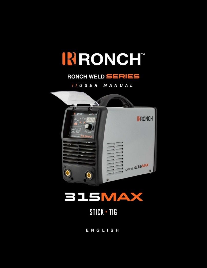
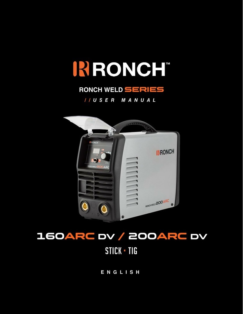
Ronch Ronch Weld Series User manual

SERIES
200MAX
STICK •TIG

2
CONTENT
1. Safety •3
2. SUMMARY •4
3. ELECTRICAL PRINCIPLE DRAWING •5
4. PARAMETERS •6
5. OPERATION CONTROL & CONNECTORS •7
6. INSTALLATION & ADJUSTMENT •8
6.1. Installation •8
6.2. OPERATION •8
6.3. WELDING TABLE •9
7. OPERATION NOTICES •10
7.1. Installation •10
7.2. Safety •10
8. MAINTENANCE •11
9. TROUBLESHOOTING & SERVICE •12

3
1. Safety
Welding may damage your body or others, so please take protection measure in operation.
Only ones who are trained professionally can install, debug, operate, maintain and
repair the equipment.
Do not maintain and repair the machine when the machine is connected with
power.
Electric shock can kill.
Never touch electrical parts.
Wear dry, hole-free gloves and clothes to insulate yourself.
Insulate yourself from work and ground using dry insulation. Make certain the
insulation is large enough to cover your full area of physical contact with work and ground.
Ensure to install the equipment correctly and ground the work or metal to be welded to a good
electrical (earth) ground according the operation manual.
Ensure to operate the equipment in safe position.
Fumes and gasses can be dangerous!
Welding may produce fumes and gases hazardous to health. Avoid breathing these
fumes and gases. When welding, keep your head out the fume.
Using enough ventilation and/or exhaust at the arc to keep fumes and gases away
from the breathing zone.
Welding sparks can cause fire or explosion.
Remove fire hazards from the welding area. If this is not possible, cover them to
prevent the welding sparks from starting a fire. Remember that welding sparks
and not materials from welding can easily go through small cracks and openings to
adjacent areas.
Do not weld enclosed tanks or containers.
Prohibit to use welder to unfrozen.
Have a fire extinguisher readily available.
Hot parts can lead to burn.
Do not touch the hot parts.
Please use the torch after cooling or use the welding blow lamp.
The people with heart-pacemaker should be away from the welding arc.
Rotating parts may be dangerous.
Far away from rotating parts. (Like fan)
Keep the parts of machine in the safe position.

4
2. SUMMARY
ARC series (discrete) welder is a MMA arc welder which adopts the insulated gate bipolar
transistor (IGBT) power module.
It can change work frequency to medium frequency so as to replace the traditional hulking work
frequency transformer with the cabinet medium frequency transformer.
Thus, it is characterized with portable, small size, light weight, low consumption and noise etc.
ARC series (discrete) has excellent performance: constant current output makes welding arc more
stable; fast dynamic response speed reduces the impact form the arc length fluctuation to the
current.
There are also some automatic protection functions for under voltage, over current, over heat,
etc. inside the welders, when the problems listed before occurred, the alarm on the front panel is
light and at the same time the output current will be cut off. It can self-protect and prolong the
using life and greatly improved the reliability of the welders.
ARC series can be ignited easily, also with little splash and good weld bead.
ARC series (discrete) is widely used in Petroleum, chemical, mechanical, shipbuilding,
architecture, boiler, pressure container, war industry and installation and so on. This machine has
high duty cycle even in the 40℃, which can keep the continuous operation. The frame is Stability
of the machine, which can keep working under high temperature and corrosion environment.
34(V)

5
3. ELECTRICAL PRINCIPLE DRAWING
P O W E R P C B
O n O f f S w i tc h/
2 2 0 V A C
Front Panel

6
4. PARAMETERS
Models
Parameters
RONCHWELD 200MAX
Power Supply Voltage (V)
1~220/230/240±10%
Frequency(HZ)
50/60
Rated Input Power(KW)
6.8 MMA
4.5 TIG
Rate Input Current(A)
47 MMA
32 TIG
Duty Cycle(40℃10min)
60% 200A
100% 155A
No Load Voltage(V)
61
Welding Current Range(A)
10-200
Efficiency (%)
≥85%
Power Factor
0.70
Net Weight(Kg)
6.2
Protection Class
IP23
Insulation Class
H
Dimensions(mm)
365*150*240
Electrode Diameter
Φ1.6 ~Φ5.0
Electrode Type
6013,7018 etc.
Note: The above parameters are subject to change with the improvement of machines.

7
5. OPERATION CONTROL & CONNECTORS
(1) Positive output: Connect the welding the clamp.
(2) Negative output: Connect to pliers.
(3) Welding current adjustment knob: Turn this knob to adjust the output current size.
(4) Power indicator: power indicator, power on light on.
(5) Alarm light: alarm indicator, lights that occurred over voltage, over current, or overheating
inside the machine, is protected.
(6) Current digital display
(7) Power switch: control power through and break.
(8) Fan: Help plant cooling.
(9) Power Access client: access to cable.
(10)Conversion switch: choose (left) LIFT TIG; choose (right) MMA.

8
6. INSTALLATION & ADJUSTMENT
Note: Please follow steps in strictly accordance with installation!
Electrical connection operation must be shut after power distribution box power switch!
The equipment protection level is IP23. Do not use it in the rain!
•6.1. Installation
(1) Each machine is equipped with a power cable should be based on the input voltage welding
power cable connected to the appropriate position, not to pick the wrong voltage.
(2) With the corresponding input power supply terminal or socket good contact and prevent
oxidation.
(3) With a multi meter measure the input voltage is within the fluctuation range.
(4) To clamp the with welding front panel connector into the jack at the bottom of the cathode,
clockwise tighten.
(5) To clamp the cable plug into the front panel below the negative welding socket, tighten
clockwise.
(6) The power ground is well grounded.
Above (4) and (5) for the DC reverse method. Operator also on the base metal and welding rod to
choose DCSP method. In general, the basic electrode reverse method is recommended (ie,
connected to the positive electrode), acid electrode makes special provisions.
•6.2. OPERATION
(1) According to the above method to install is correct, turn the power switch, so that the power
switch is “ON” position, then the power indicator light, the fan comes on, the device work
properly.
(2) Note the polarity of wiring, the general DC welding wire in two ways: positive and reverse
polarity connection method. Positive Connection: Welding clamp then negative, then positive,
then positive work piece; reverse law contrary. Selected according to the technical
requirements of welding the appropriate connection, is you choose incorrectly will result in
arc instability and spatter large adhesion and other phenomena, such cases can be quickly
reversed to joints.
(3) If the work piece distance from the welding machine, the second line (electrode holder and
ground) is longer, so choose the appropriate conductor cross-sectional area should be larger
to reduce cable voltage drop.
(4) According to the standard, model pre-set welding electrode current, electrode clip will be
good, you can use short-circuit arc welding, welding parameters can refer to 6.3.

9
•6.3. WELDING TABLE
Note: The following table applies to low-carbon steel, other materials, please refer to related
information.
Electrode diameter (mm)
Recommended welding
current(A)
Recommended welding
voltage(V)
1.0
20~60
20.8~22.4
1.6
44~84
21.76~23.36
2.0
60~100
22.4~24
2.5
80~120
23.2~24.8
3.2
108~148
23.32~24.92
4.0
140~180
24.6~27.2

10
7. OPERATION NOTICES
•7.1. Installation
(1) Welding environmental temperature should be between -10℃to 40℃.
(2) Welding should be done in relatively dry environments, the air humidity of not more than
90%.
(3) To avoid areas containing dust or corrosive gas welding operation environment.
(4) To avoid sunlight or rain, welding, do not le water or rain water infiltrated the welding
machine.
(5) To avoid the strong air flow environment for gas welding operations.
•7.2. Safety
Welding machine has been installed in over-voltage, over current and over temperature
protection circuit, when the grid voltage, output current and the internal temperature exceeds the
set temperature, the welding machine will automatically stop working; but excessive use will
result in welding damage, so you need to note the following:
(1) To ensure good ventilation!
The welder at work have a greater current flow through the cooling of natural ventilation van not
meet the requirements of welding, it is equipped with cooling fans to help the welder. Before
using, please check the vents to make sure it has not been blocked or covered the distance
between the object and the surrounding welding should not be less than 0.3 meters, welding
machines should have been so good ventilation, to ensure the normal operation of welding
machine extending welder life.
(2) Prohibit the overload!
By welding machine operators should ensure that the duty cycle to allow use of welding (see
technical data table), keeping the welding current within the normal range, if the current overload
will shorten the life of welding machine welding machine and may even burn.
(3) Prohibits the over-voltage!
Supply voltage listed in the “Technical Data Sheet”, the general case, the welding voltage within
the circuit will automatically compensate to ensure that the welding current in the permitted
range. If the voltage exceeds the allowable value, will damage the welder, the user should be fully
aware of this situation, take appropriate preventive measures.
(4) After each welding machine comes with grounding screw, and marked with ground markers.
Before use, use a larger than 2.5mm cable, in the welding chassis ground to discharge any
static electricity or to prevent leakage accidents.
(5) If the welding work over the standard loading time, the welding machine may suddenly stop
working into the protected status, which means that the load beyond the standard rate of
welding, excessive heat triggered a temperature control switch, the welding machine to stop
working, while front panel alarm indicator lights up. In this case, you do not unplug the power
plug, to maintain the cooling fan rotation. The red light goes out, the temperature dropped to
a reasonable extent, and then you can restart welding.

11
8. Maintenance
The following operations require the operator has sufficient electrical expertise and
comprehensive Safety knowledge, the operator can demonstrate its capacity to be held
valid qualifications and knowledge Documents. Make sure to open the case welding
power input cable power input cable has broken.
(1) Periodic inspection welding internal circuit connections, make sure connections are
correct and reliable connection, (especially the joints or components). If any rust and
loose application of sanding off rust layer and the oxide film, reconnect, and tighten.
(2) The machine power, do not allow hands, hair and tools near live components inside
the machine, such as: fans, so as mot to hurt or cause damage to the machine.
(3) Regularly with a clean dry compressed air to dust the machine, compressed air
pressure should be at reasonable levels in order to avoid damage to the welding of small
components inside. Dust the machine works well, no dust under normal circumstances
(except in exceptional circumstances).
(4) Avoid water or water vapor into the welding machine inside, if there is such a case, the
internal welding machine should be dried. Then measured with a mugger insulation of the
welding machine (including the connections between nodes and the connection point
with the case of companies). Only confirms that no unusual circumstances, can continue
to welding work.
(5) Regular inspections for damage the cable insulation, if any, to wrap or replace the
cable.
(6) If not using welding machine, welding machine should be back in the box and kept in a
dry environment.

12
9. Troubleshooting & SERVICE
The following operations require the operator has sufficient electrical expertise and
comprehensive Safety knowledge, the operator can demonstrate its capacity to be held valid
qualifications and knowledge Documents. Make sure to open the case welding power input cable
has broken.
Common Faults and exclusion method:
Symptom
Solution
Power indicator does not light, fan does not
turn, no welding output.
Make sure the power switch is turned on.
Confirm that the power input cable are
connected with electricity.
Symptom
Solution
Fan switch, or not subject to potential
instability in the welding current control,
current, big, sometimes small
The current potential is damaged, should be
replaced.
Bad connections, such as plug-in to be
checked.
Power indicator light shows the normal fan
rotating normal, no welding output.
Check all connectors inside the machine if
there is bad.
A circuit output connections or bad.
the alarm indicator light
(1) That access to protected status because
of overheating, in which case, To maintain
power, so that the temperature dropped to
the machine fan Reasonable temperature,
until light goes out, you can continue
working;
(2) Check the thermal switch is damaged,
such damage, to be Replacement.
Hot welding clamp
Welding clamp rated current is too small, the
replacement of larger size welding clamp.
Manual welding big splash
Output polarity is unreasonable, reversed
output connector

13
200MAX
STICK •TIG
Other manuals for Ronch Weld Series
2
This manual suits for next models
1
Table of contents
Other Ronch Welding System manuals
Popular Welding System manuals by other brands

FRONIUS
FRONIUS KD Supply 2500 operating instructions

Ditch Witch
Ditch Witch PR95 Operator's manual

Sel
Sel RI2000 instruction manual

FRONIUS
FRONIUS ROB 4000 TIG operating instructions

FRONIUS
FRONIUS VARIOSTAR 357 operating instructions

Vanair
Vanair ALL-IN-ONE POWER SYSTEM AIR N ARC 150 Series Operations manual & parts list