Ronch Ronch Weld Series User manual

1
SERIES
200TIG/250TIG
STICK •TIG

2
CONTENT
1. Safety •3
2. SUMMARY •4
3. ELECTRICAL PRINCIPAL DRAWING •5
4. PARAMETERS •6
5. INSTALLATION •7
6. OPERATION •9
7. OPERATION NOTICES •11
8. POSSIBLE PROBLEMS IN WELDING PROCESS •12
9. MAINTENANCE •13
10. Troubleshooting & SERVICE •14

3
1. Safety
Signal
Warning
Mis-operation will cause huge potential dangers,
which will lead to death or serious injury.
High
danger
Mis-operation will cause huge potential dangers,
which will lead to death or serious injury.
Danger
Mis-operation will cause huge potential dangers,
which will lead to death or serious injury.
Notice
Mis-operation will lead to moderate or slight
injury, and also will cause damage to the
materials.
Danger
Never touch the electrical parts, or may suffer
deathful shock and burn.
Danger
When welding in confined area, pay more
attention on ventilation, to ensure breathing air
is safe.
Earthing
Ensure the machine cover is well grounded.
Notice
Do not use the machine unassembled with the
machine cover or other protection equipments.
Keep fingers, clothing, hair, etc, away from the
rolling parts such as cooling fan when operating,
to avoid injury.
Notice
Welding spatter, welding slag and the hot work
pieces will cause fire if touch the combustible
materials. Ensure all of the connections in the
power supply circuit, welding circuit are in good
condition, or may lead to partially over heat. Do
not weld hermetic containers or tanks
containing combustible materials, or will cause
explosion or cracks.
Notice
The temperature of the inside winding is beyond
normal level, thermal relay acts automatically.

4
2. SUMMARY
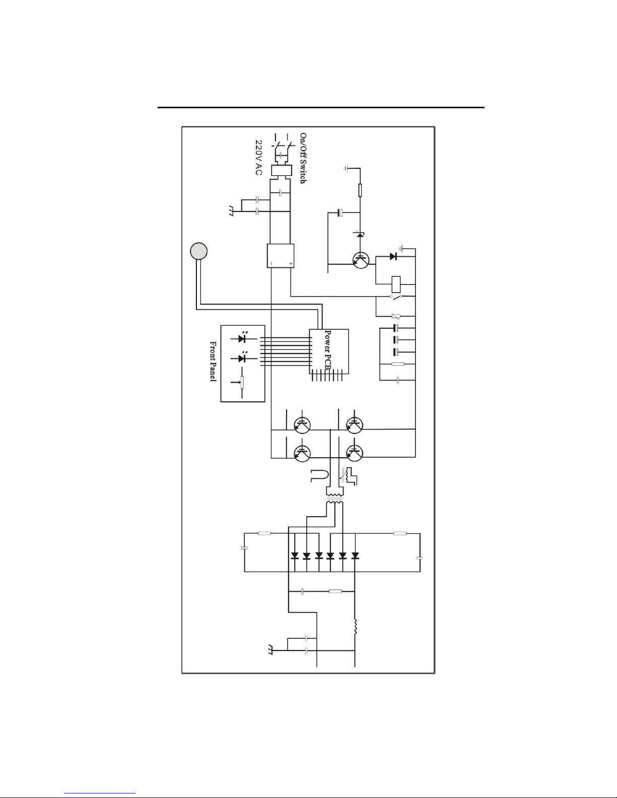
TIG series welder is a TIG welder which adopts the insulated gate bipolar transistor (IGBT) power
module. It can change work frequency to medium frequency so as to replace the traditional
hulking work frequency transformer with the cabinet medium frequency transformer. Thus, it is
characterized with portable, small size, light weight, low consumption and noise etc.
Excellent welding performance
TIG series has excellent performance: constant current output makes welding arc more stable; fast
dynamic response speed reduces the impact from the arc length fluctuation to the current.
There are also some automatic protection functions for over voltage, over current, over heat, etc.
inside the welders, when the problems listed before occurred, the alarm on the front panel is light
and at the same time the output current will be cut off. It can self-protect and prolong the using
life and greatly improve the reliability and practicability of the welders.
TIG series can be ignited easily and with good weld bead.
TIG series has wide range of applications. Given its small size, light weight, easy and flexible
operation, it can be used in various kinds of environment, such as working aloft, field work,
interior decoration,etc.
High duty cycle. In 40℃environment, TIG series’duty cycle can reach 40%, so that can keep
continuous operation.
Stable structures
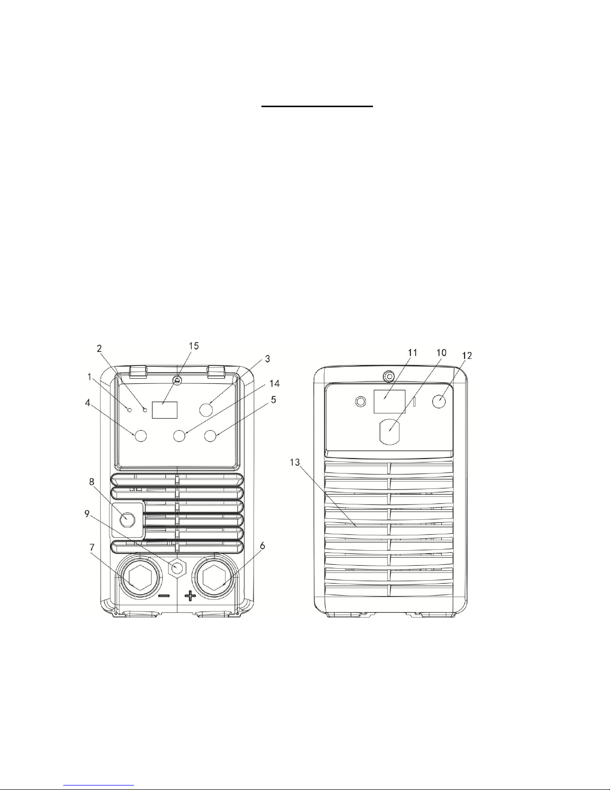
The front and rear panel are made of engineering plastic, that have features of heat-resistant,
corrosion-resistant, to ensure the welder keep normal work even under bad environments.

5
3. ELECTRICAL PRINCIPAL DRAWING

6
4. PARAMETERS
Model
TIG 180S
TIG 180
TIG 200
TIG 220
TIG 250-1
Rated input
voltage (V)
1~220/230/
240±10%
1~220/230/2
40±10%
1~220/230/
240±10%
1~220/230/24
0±10%
1~220/230/24
0±10%
Frequency(HZ
)
50 / 60
50 / 60
50 / 60
50 / 60
50 / 60
Rated input
power(KW)
3.8
TIG
-
3.1
TIG
5.5
MMA
4.5
TIG
7.0
MM
A
5.0
TIG
7.2
MMA
6.1
TIG
8.8
MMA
No-load
voltage(V)
74
63
63
63
70
Welding
current
range(A)
10~180
10~180
10~200
10~220
10~250
Duty
cycle(40℃
10min)
40% 180A
40% 180A
35% 200A
30% 220A
40% 250A
100% 115A
100% 100A
100% 100A
100% 100A
100% 180A
Post flow(S)
0~7
0~7
0~7
0~7
0~7
Rated input
current(A)
29(
TIG)
-
22
(TIG
)
36
(MM
A)
33(
TIG
)
46
(MM
A)
35
(TIG
)
50
(MM
A)
40(TI
G)
55(M
MA)
Efficiency (%)
85%
85%
85%
85%
85%
Power factor
0.75
0.75
0.75
0.75
0.75
Protection
class
IP23
IP23
IP23
IP23
IP23
Insulation
class
H
H
H
H
H
Dimensions(
mm)
410×146×278
450×190×350
Net
weight(kg)
5.0
5.5
5.5
5.7
10

7
5. INSTALLATION
TIG series has equipped with power supply compensating system, so it can keep work if the power
supply only floating in the range 15% more or less than the rated input power.
If the used cable is much longer, we recommend using larger-size cable to reduce the voltage
drop. Because if the cable is too long, it may affect the welder’s arc starting performance or affect
the system’s normal working.
Make sure the vent of the machine is not covered or blocked, the ventilation system is effective. .
Connect well with the shield gas supply. The gas supply system should include gas bottle, argon
decompression flow meter and hose, the connection part of the hose should be fasten by hose
clamp or something like it, to avoid leakage or air inlet.
Connect the machine cover with the earth cable which should be at least 6mm2 .One method is to
connect the grounding screw which on the back of the machine to the earth equipment. The other
method is to ground the power supply socket’s earth connection separately. And it is also OK to
use these two methods simultaneously to ensure safety.
Connect the welding torch correctly according to the picture as below, TIG operation mode: fasten
the welding torch’s electrical-gas integration connector to the joint on the front panel, fasten the
aero socket to the corresponding joint.TIG series should be installed according to picture 1 as
below.
Power supply cableDistributor box
Gas flow regulation
Argon gas
Work piece
(Picture 1)

8
Power supply cable Distributor box
Work piece
(Picture 2)
If the power supply equipment is put on slope, pay attention on preventing it from toppling. .
Prohibit using the power supply for unfreezing the pipeline.
Connect the fast plug of the earth cable to the positive electrode of the welding machine panel
and tighten it clockwise. Use the earth clamp to clamp the work piece; connect the welding gun
cable to the negative electrode of the machine panel.
Connect the power cable to the matching distributor box according to the voltage grade; do not
connect the wrong one. And also should ensure the voltage difference is within the allowance.
After above steps, the installation is finished, and can start welding operation.
Warning!
All of the connections can be done only after the power supply is
shut off. The correct sequence is connecting the electrode holder or
welding torch and the earth cable to the machine firstly, and then
checking to make sure the connection is correct, reliable and no
loose, connecting the power cable plug to the power supply at last.

9
6. OPERATION
TIG operation:
Turn on the power on/off switch, power pilot lamp lights, and the fan starts rotating.
Turn on the argon gas switch, adjust the flow rate to the rated standard (you may refer to the
parameter sheet).
Solenoid valve opens after pressing the start-switch of the welding torch, and you will hear the
electric discharge sound of high frequency spark, and there will be argon flow out from the
welding torch’s mouth at the same time. Attention: when first time operation, you should keep
pressing the switch for several seconds till the air in the pipeline has been totally exhausted. When
stop welding, there will still argon flowing out for several seconds, this is specially designed to
ensure enough shield for the welding spot before cooling. So should hold the welding torch on the
welding part for some time after the arc light off.
Set proper current according to the work piece’s thickness and technological requirements.
Keep electrode 2~4 mm away from the work piece, press the welding torch control switch, there
will be high frequency electric discharge between the electrode and work piece. The high
frequency arc starting spark will disappear once the arc is ignited, and the welding is beginning.
(1) Power pilot lamp: This pilot lamp when lit indicates that the machine is on.
(2) Alarm pilot lamp: This pilot lamp when lit indicates that the protection of the machine has
been activated.
(3) 2T/4T/MMA: Select 4T、2T or MMA operation mode.
(4) Welding current regulation knob: Set welding current.
(5) Post gas flow regulation knob: adjust the time of post gas flow.

10
(6) Positive output: Connect with welding electrode or connect to earth when use TIG
function.
(7) Earth connection: Connect with earth clamp.
(8) Welding gun switch: connect with duplex aviation.
(9) Welding gun connection: Connect with the welding gun.
(10)Cable clamp: Fastened the main cable.
(11)On/off switch: Control the power supply on and off.
(12)Gas inlet: Gas inlet connection.
(13)Fan: Cooling the machine.
(14)Down slope regulation knob: adjust the time of down slope.
(15)Current digital display
MMA operation:
1. Turn on the machine, and the fan start to work;
2. Put the conversion switch to MMA. It means the machine can be used as MMA welder;
3. Choose the suitable welding current according to the thick, place and work situation of the
work piece (Now the machine is in the standby state of MMA mode).

11
7. OPERATION NOTICES
Environments
(1) Welding should be done in relatively dry environments, the air humidity should be no
more than 90%. Welding environment temperature should be between -100C~400C.
(2) Avoid operating the machine in sunlight or rain, do not let water or rain water infiltrate
the welding machine.
(3) Avoid welding operation in dusty areas or under corrosive gas environment.
(4) Avoid gas welding in strong air flow environments.
Safety
TIG series has been installed in over voltage, over current and over heat protection circuits, when
the grid voltage, input current and the internal temperature exceeds the set standards, the
welding machine will automatically stop working; but excessive use will cause damage to the
machine, so you need to note the following safety items:
(1) To ensure good ventilation to this kind of small welding machine, there will be greater
current through over when working while the natural ventilation is not enough to meet
the cooling requirements of welding, so it needs to equip with a fan to cool the machine
effectively and help it to work stably. The operator should ensure good ventilation, other
surroundings should keep at least 0.3 meters away from the machine, as it is very
important to help the machine has better performance and longer using life.
(2) To prohibit the over-load or over-voltage The operator should keep observing the Max.
permited load current (corresponding to the selectable duty cycle), to ensure the welding
current not exceed the Max. permited load current, as over current will obviously reduce
the life of the welding machine or even burn the machine; Supply voltage listed in the
“Parameters sheet”; In general cases, the voltage automatic compensation circuit inside
the machine will ensure that the welding current within the permitted range. If the
voltage exceeds the allowable value, the machine will be damaged.
(3) There is a ground screw marked with ground markers at the back of each welding
machine. Before operating, use an earth cable larger than 6.0mm2to connect with the
machine to avoid discharging any static electricity or to prevent leakage accidents.
(4) If the welding machine works over the duty cycle, it may suddenly stop working and into
protected status, this means the load exceeds the standard duty cycle, and the excessive
heat triggers the temperature control switch so that the machine stops working and the
alarm indicator on the front panel lights at the same time. In this case, you need not to
disconnect the power plug, so as to keep the fan working to cool the machine. When the
alarm indicator lights off, the temperature drops to a standard extent, then you can
restart welding.

12
8. POSSIBLE PROBLEMS IN WELDING
PROCESS
1. Black welding spot
This means the welding spot is oxidized without effective protect. You can check as below:
1) Ensure the valve of the Argon gas tank is open, and with enough pressure. In
general, when the inside pressure of a tank lower than 0.5Mpa, you should change
the tank
2) Check if the Argon flow is open and if the flow is enough. To save the gas you can
choose different flow according to different welding current. But if the flow is too
weak, the welding spot will not be covered wholly.
3) It will cause the problem of welding quality if the gas circuit is bad sealed or the
purity of the gas is not high.
4) The welding quality will be reduced if the machine is used in the place with strong
air flow.
2. Hard to start the arc and the arc is easy to be broken.
1) Ensure the quality of the tungsten electrode is good.
2) Tungsten electrode without processed will caused the unsteady arc. Before
welding work, the arc end of the electrode should be processed to conical.
3. The output current can’t reach to the rated value
The power voltage is different from the rated value will cause the inconsistency between the
output current and rated current. When the power voltage lower than rated value, the max
output current maybe lower than rated value.
4. The current can’t be keep stable in welding process
1) Maybe caused by the change of network voltage;
2) Maybe caused by the interference of the network power or other electric-used
equipments.
5. Strong splash when use MMA function
1) Maybe the welding current is too large, and the electrode’s diameter is two small.
2) Reverse connection of the output. In general, the electrode should be connected
to the positive output, and the workpiece be connected to the negative output.

13
9. Maintenance
The following operations require the operator should have sufficient
electrical expertise and comprehensive safety knowledge, the operator
should hold valid qualifications to demonstrate his capacity and knowledge.
Make sure power input cable has been disconnected before opening the
machine cover.
(1) Periodically inspect internal circuit connections status, make sure connections are
correct and reliable, (especially the joints or components). If any rust and loose is
found, should use the stand paper to burnish off the rust and oxide film, then
connect again and tighten it.
(2) When the machine is charged, do not put hands, hair and tools near electrified
components such as fan inside the machine, to avoid hurt or cause damage to the
machine.
(3) Periodically dust the machine with clean and dry compressed air, and the
compressed air should be at reasonable levels to avoid damage to the small
components inside the machine. This series has good dust proof performance, it
needs no dusting under normal cases (except for exceptional circumstances).
(4) Avoid water or water vapor enters the welding machine. If there is such a case, the
internal welding machine should be dried. Then measure it with a megger about
the insulation status (including the connections between nodes and the
connection point with the machine cover). Only confirm there is no unusual
circumstance that can continue welding work.
(5) Periodically inspect whether the insulation cover of the cable has breakage, if so,
wrap the breakage or change the cable.
(6) If it is going to not use the welding machine for long time, should put the machine
back into the packing carton and keep it in a dry environment.

14
10. TROUBLESHOOTING & SERVICE
The following operations require the operator should have sufficient electrical
expertise and comprehensive safety knowledge, the operator should hold valid
qualifications to demonstrate his capacity and knowledge. Make sure power input
cable has been disconnected before opening the machine cover.
Common faults and exclusion method:
Symptom
Solution
Power indicator does
not light, fan does not
rotate, no welding
output
1、Make sure the power switch is turned on.
2、Check to confirm that the power input cable is connected well with
the grid.
The fan rotates, alarm
indicator does not
light, no HF electric
discharge, touch
striking arc is OK.
1、Check all connectors inside the machine whether there is problem;
check whether the welding torch’s control cable is break.
2、It may be caused by circuit defect, check the reason and contact
with the after-service.
Alarm indicator does
not light, have high
frequency, no welding
output.
1、Welding torch’s cable is break. Earth cable breaks or has not been
connected with the work piece.
2、The connections between the positive output terminal or welding
torch output terminal with the inside part of the machine are loose.
Alarm indicator does
not light, no high
frequency, touch
striking arc is OK.
1、The connection between the primary coil of arc starting
transformer and the power panel is bad, should re-connect them.
2、The input cable from power switch to power panel AC220V drops
off.
3、Some components of the high voltage electric starting arc circuit
are damaged, find them out and change them with the new ones.
Alarm indicator lights,
no output.
1、It is may because of over current protection, turn off the machine.
Restart the machine after the alarm indicator is off and it should be
normal.
2、Also may because of overheat protection, no need to turn off the
machine but just wait for 2~3 minutes, then it may come normal. If the
alarm indicator does not light, it may be caused by control PCB power
short-circuit or damage.
Power indicator is
flashing, alarm
indicator does not
light, no output.
Input over voltage or short voltage, check the input power.
When the machine is turn on, there is welding output load,
thermistance block the input power supply. Turn off the machine and
wait for several seconds then turn on the machine without load.
Input current is
unstable or not
controlled by the
potentiometer.
If it is because of the potentiometer damage, replace the
potentiometer. Or if it caused by the bad connections, especially
socket connector, need inspection.

15
200TIG/250TIG
STICK •TIG
Other manuals for Ronch Weld Series
2
This manual suits for next models
2
Table of contents
Other Ronch Welding System manuals
Popular Welding System manuals by other brands

SAF
SAF NERTINOX 250 P PONTICELLI Safety instruction for use and maintenance

Miller
Miller Multimatic 220 AC/DC owner's manual

widos
widos PSM 10 XHS Working Instructions Translation

Lincoln Electric
Lincoln Electric INVERTEC V300-I Service manual

Paton
Paton PRO-315-400V Data sheet and operating manual

Miller
Miller HDC 1500A owner's manual