RONK 100-600 AMP Quick start guide
OWNER’S & INSTALLATION MANUAL
100-600 AMP
RONK Automatic Transfer Switch

2 RONK Automatic Transfer Switch Owner’s Manual
DISCLAIMERS:
All information, illustrations and specications in this manual are based on the latest information available
at the time of publishing. The illustrations used in this manual are intended as representative reference
views only. Moreover, because of our continuous product improvement policy, we may modify information,
illustrations and/or specications to explain and/or exemplify a product, service or maintenance
improvement. We reserve the right to make any change at any time without notice. Some images may vary
depending upon which model is shown.
ALL RIGHTS RESERVED:
No part of this publication may be reproduced or used in any form by any means – graphic, electronic,
or mechanical, including photocopying, recording, taping or information storage and retrieval systems –
without the written permission of RONK Electrical Industries, Inc.
ORIGINAL INSTRUCTIONS (English):
The English version of this manual controls over any error in or conicting interpretation of any translation.

RONK Automatic Transfer Switch Owner’s Manual 3
TABLE OF CONTENTS
INTRODUCTION 5
Contact Information 5
Automatic Transfer Switch (ATS) 5
Generator 5
SAFETY 6
Important Safety Instructions 6
Safety Symbol Meanings 6
Safety Labels 7
General Safety Precautions 7
PRODUCT SERIES 8
RONK ATS Product Overview 8
Receiving, Handling and Storage 8
Receiving 8
Handling 8
Storage 8
SPECIFICATIONS 9
RONK ATS 100A/200A/400A/600A Specications 9
INSTALLATION AND WIRING 10
General Information 10
Mounting Location 10
Mounting Requirements 10
Recommended Upstream Protection 11
Power Connections 11
Wire Sizes & Torque 11
Connections 12
GENERAL OPERATION 13
RONK ATS General Operation 13
QUICK START GUIDE 14
Setting Time of Day (TOD) 14
Scheduler 14
208V System Settings 14
ATS Factory Set Trips and Time Delays 15
Mode Selection Operation 16
Graphical Display 17
Display Pages 17
Status 17
Instrumentation 18
Alarms 19
Scheduler 19
Alarm Icons 19

4 RONK Automatic Transfer Switch Owner’s Manual
TABLE OF CONTENTS
Controls 20
Mode Selection 20
Display 20
Load Switching Control 20
MANUAL TRANSFER 21
Manual Transfer of Mechanism 21
100A/200A Manual Transfer 21
400A Manual Transfer 21
600A Manual Transfer 22
MAINTENANCE 23
Recommended Maintenance 23
Maintenance 23
DRAWINGS 24
100A & 200A, 240V Schematic 24
400A, 240V Schematic 25
400A, 480V Schematic 26
600A, 240V Schematic 27
600A, 480V Schematic 28
WARRANTY 29
Owner Warranty Policy 29
Limited Warranty 29
Warranty Period 29
Warranty Registration Process 29
About Our Warranty 29
NOTES 30

RONK Automatic Transfer Switch Owner’s Manual 5
INTRODUCTION
Thank you for your purchase of a RONK Automatic Transfer
Switch (ATS). This product is designed for use with standby
generators. When operated and maintained according to the
instructions in this manual, your system will provide many years
of standby electrical energy service.
This manual contains important safety instructions for
installation and operation of this ATS. We have made every
eort to provide safe, ecient instructions for installation
and operation. However, as every installation is unique, it is
impossible to anticipate every possible procedure and method
to obtain a properly installed unit. It is important that you read
and understand these instructions thoroughly before attempting
to install or operate this unit. Your equipment is supplied with
this combined Installation and User Manual. This is an important
document and should be retained by the owner after the
installation has been completed.
This ATS requires professional installation before use. Refer
to the installation section of this manual for instructions on
installation procedures. Only licensed electrical contractors
should install an ATS. Installations must comply completely with
all federal, state and local codes, standards and regulations. Your
installer should follow these instructions completely. Every eort
has been made to ensure that the information in this manual is
both accurate and current. However, the manufacturer reserves
the right to change, alter or otherwise improve the system at any
time without prior notice.
CONTACT INFORMATION
There are several ways to contact us for answers to questions
you may have about your product. Contact Technical Services by
phone at 1-217-563-8333 Monday through Friday 8 AM to 4:30
PM Central Time or email [email protected].
For your future reference, record the following pertinent
information. This information will help to identify product
information should you need to contact RONK’s Technical
Services department.
ATS
Model Number:
Description:
Serial Number:
Installation Date:
GENERATOR
Model Number:
Description:
Serial Number:
Installation Date:
NOTICE
Please check with the generator manufacturer to ensure the
RONK ATS switch is compatible.
6 RONK Automatic Transfer Switch Owner’s Manual
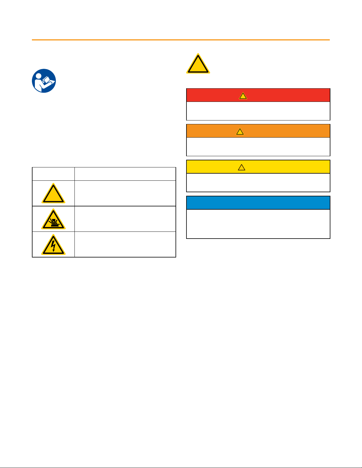
!
This safety alert symbol appears with most safety
statements. It means attention, become alert, your
safety is involved! Please read and abide by the
message that follows the safety alert symbol.
!
DANGER
Indicates a hazardous situation which, if not avoided, will result
in death or serious injury.
!
WARNING
Indicates a hazardous situation which, if not avoided, could
result in death or serious injury.
!
CAUTION
Indicates a hazardous situation which, if not avoided, could
result in minor or moderate injury.
NOTICE
Indicates a situation which can cause damage to the
equipment, personal property and/or the environment, or
cause the equipment to operate improperly.
NOTE:
Indicates a procedure, practice or condition that should be
followed for the ATS to function in the manner intended.
The manufacturer of this product cannot reasonably anticipate
every possible circumstance that might involve a hazard. The
warnings in this manual and the tags and decals axed to the
unit are, therefore, not all-inclusive. If you use a procedure, work
method or operating technique that the manufacturer does not
specically recommend, you must ensure that your method
is safe for you and others. You must also make sure that the
procedure, work method or operating technique that you choose
does not render the equipment unsafe.
SYMBOL DESCRIPTION
!
Safety Alert Symbol
Crush Hazard
Electrical Shock Hazard
SAFETY
IMPORTANT SAFETY INSTRUCTIONS
Read Manufacturer’s Instructions.
SAVE THESE INSTRUCTIONS.
• This manual contains important information that should be
used during installation, maintenance, and operation of this
unit.
• Read all the instructions and safety symbols thoroughly before
attempting to install, operate and/or service this equipment.
SAFETY SYMBOL MEANINGS

RONK Automatic Transfer Switch Owner’s Manual 7
SAFETY
SAFETY LABELS
Always replace any illegible or missing labels
immediately. All safety labels must be legible to alert
personnel to safety hazards
Figure 1
GENERAL SAFETY PRECAUTIONS
!
DANGER
DANGER! Equipment contains high voltage.
Despite the safe design of the system, operating
this equipment imprudently, neglecting its
maintenance or being careless can result in
death or serious injury.
!
WARNING
The safety messages that follow have WARNING
level hazards.
• Unauthorized or improper installation, operation, application,
or repair of this equipment is extremely dangerous.
• Only qualied electricians should attempt installation of this
equipment, which must strictly comply with all applicable
codes, standards and regulations.
• When connecting a generator system to an electrical system
that is normally supplied by an electric utility company,
always comply with regulations of the National Electrical
Code (NEC) (Article 701 Legally Required Standby Systems
or Article 702 Optional Standby Systems, as applicable), and
Occupational Safety and Health Administration (OSHA), as
applicable. It is essential to use the latest version of any
standard to ensure all current information is applied.
!
WARNING
The safety messages that follow have WARNING
level hazards.
• Failure to properly ground equipment can result in
electrocution.
• Do not touch bare wires.
• Do not use equipment with worn, frayed, bare or
otherwise damaged wiring.
• Do not handle electrical cords while standing in water,
while barefoot, or while hands or feet are wet.
• If you must work around a unit while it is operating,
stand on an insulated dry surface to reduce shock
hazard.
• Do not allow unqualied persons or children to service
equipment.
• In case of an accident caused by electrical shock,
immediately shut down all sources of electrical power
and contact local authorities. Avoid direct contact with
the victim.
• Low-voltage wire cannot be installed in the same conduit as
power voltage wiring.
• Dangerous power voltages are present inside a live ATS.
Never work on the ATS unless all power voltage supplies to
the switch have been turned o.
• When an ATS is connected to a standby generator, the
generator engine may crank and start at any time without
notice to the end user. To avoid injury that may be caused
by such start-ups, move the safety disconnect switch on
the front panel to the OFF position before working on this
equipment.
NOTICE
Improper treatment of equipment can damage it and shorten
its life.
• Use equipment only for intended uses.
• If you have questions about intended use, contact RONK
Electrical Industries, Inc.
• Do not expose equipment to excessive moisture, dust, dirt or
corrosive vapors.
• Always remain alert while working on this equipment. Never
work on the equipment when you are physically or mentally
fatigued.
• If connected devices overheat, turn them o and turn o
their circuit breaker or fuse.

8 RONK Automatic Transfer Switch Owner’s Manual
RONK ATS
RONK ATS PRODUCT OVERVIEW
RONK automatic transfer switches are designed to automatically
transfer an electrical load to standby (emergency) power source
in the event of an over/under voltage or frequency condition
on any or all phases of the utility power source. Upon the
restoration of the utility supply, the electrical load will be
automatically retransferred to the utility power source.
All transfer switch mechanisms incorporate a double- throw
action switching device for automatic transferring. The transfer
switch mechanism is a contactor-operated device controlled by a
set of utility and generator solenoids.
Manual operation is also provided for manual transfer of the
load between the power sources.
Figure 2 - RONK ATS
RECEIVING, HANDLING AND STORAGE
Shipment contents:
• Automatic Transfer Switch
• DSE 331 Installation Instructions
• Owner’s & Installation Manual
RECEIVING
Every eort is made to ensure that your automatic transfer
switch arrives at its destination undamaged and ready for
installation. The packing is designed to protect the transfer
switch’s internal components as well as the enclosure. Care
should be taken to always protect the equipment from impact.
Do not remove the protective packaging until the equipment is at
the installation site and ready to be installed.
A shipping label axed to the shipping box includes a variety of
product and shipping information, such as items and customer
numbers. Make certain that this information matches your order
information.
After unpacking, inspect the switch for any damage that may
have occurred during shipping. If any missing parts or damage is
discovered when unpacking, do not return the unit to the place
of purchase; please contact RONK Electrical for instructions on
how to proceed. Never install a switch that has been damaged.
HANDLING
Always protect the equipment from impact and do not double
stack. Once the transfer switch is at the installation site and
ready to be installed, the packaging material may be removed.
STORAGE
Store the transfer switch with its protective packaging in place
until ready for installation. Always protect the transfer switch
from excessive moisture, dirty conditions, corrosive conditions
and other contaminants. It is strongly recommended that the
package-protected equipment be stored in a climate-controlled
environment of -4° to 149°F (-20° to 65°C), with a relative
humidity of 80% or less. Do not stack other equipment on top of
the stored switch.
RONK Automatic Transfer Switch Owner’s Manual 9
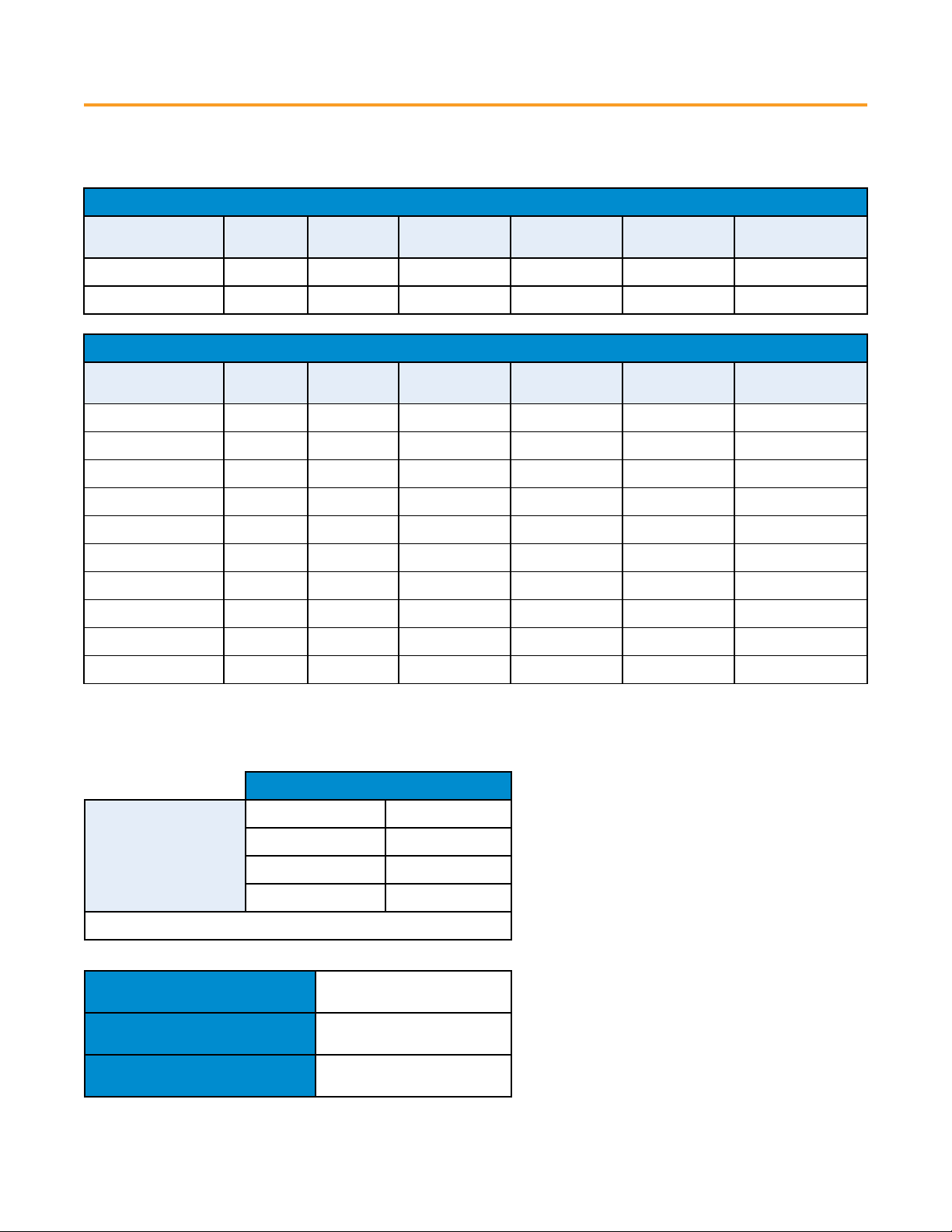
SPECIFICATIONS
100A/200A/400A/600A SPECIFICATIONS
OPTIONAL STANDBY - UL1008
PART NUMBER TYPE PHASE AMPERAGE
RATING
VOLTAGE
RATING
APPROX.
WEIGHT
APPROX. DIM.
[HxWxD]
ATS10012 V12 1100 240 48 lbs. 24 x 20 x 6
ATS20012 V22 1200 240 85 lbs. 30 x 24 x 6
EMERGENCY - UL1008
PART NUMBER TYPE PHASE AMPERAGE
RATING
VOLTAGE
RATING
APPROX.
WEIGHT
APPROX. DIM.
[HxWxD]
ATS10032 V13 3100 240 49 lbs. 24 x 20 x 6
ATS20032 V23 3200 240 86 lbs. 30 x 24 x 6
ATS40012 W04 1400 240 181 lbs. 48 x 30 x 10
ATS40014 W04 1400 480 203 lbs. 48 x 30 x 10
ATS40032 W04 3400 240 188 lbs. 48 x 30 x 10
ATS40034 W04 3400 480 210 lbs. 48 x 30 x 10
ATS60012 N06 1600 240 410 lbs. 60 x 36 x 24
ATS60014 N06 1600 480 432 lbs. 60 x 36 x 24
ATS60032 N06 3600 240 428 lbs. 60 x 36 x 24
ATS60034 N06 3600 280 450 lbs. 60 x 36 x 24
All switches are provided from factory with a solid neutral.
POWER DERATING POWER DERATING
Ambient Temperature
Rating
113°F (45°C) 100%
131°F (55°C) 90%
149°F (65°C) 75%
158°F (70°C) 70%
Do not exceed 158°F (70°C)
DC POWER CONSUMPTION 168 mA @ 12 Vdc
80 mA @ 24 Vdc
RSC RATING 8 Amp, 35 Vdc Maximum
TEST SWITCH Local or Remote Capable
10 RONK Automatic Transfer Switch Owner’s Manual
INSTALLATION & WIRING
GENERAL INFORMATION
All RONK Automatic transfer switches are factory-tested and
approved. Installation requires the mounting of the transfer
switch and external wiring for utility and generator operation.
Once the transfer switch is properly installed, it should be
visually inspected and approved before any testing is performed.
MOUNTING LOCATION
All RONK Automatic transfer switches require that adequate
lifting means be used to install the switch at its mounting
location. Be certain to choose a location that oers a at
mounting surface that can support the transfer switch. Caution
must be taken at the installation site to make sure the site is
free from excessive moisture, uctuating temperature ranges,
dust, corrosive materials, etc. Before any drilling takes place, be
certain the drilling area is free of any hazards including electrical
wiring, piping, etc. Extreme caution should be exercised when
any installation and drilling are performed to protect the transfer
switch from any debris including contaminants, lings, etc.
Any debris within the transfer switch may result in a system
malfunction.
!
WARNING
Always use adequate lifting to lift and mount the
transfer switch during installation.
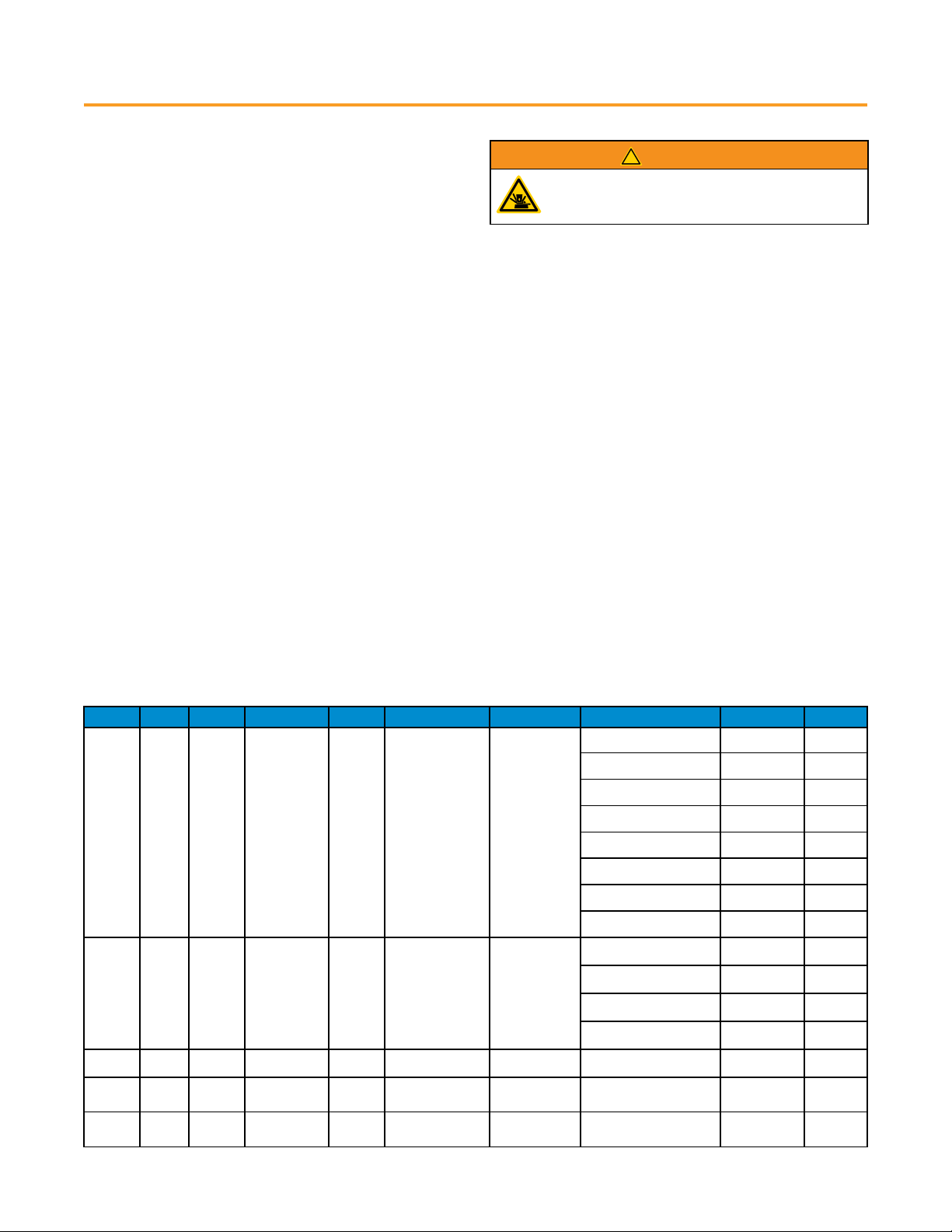
MODEL POLES AMPS MAX VOLTS ANY CB MAX DURATION SPECIFIC CB* MANUFACTURER TYPE RATING
V12
V13
1
3
100 240 10 kA 0.025 Seconds 22 kA
Siemens HED4, HED6 125 A
Siemens ED4, ED6 125 A
Siemens CED6 125 A
Eaton / Cutler Hammer FDC 150 A
Eaton / Cutler Hammer QCHW 125 A
Eaton / Cutler Hammer FCL 100 A
Eaton / Cutler Hammer FB 100 A
SQUARED D FI 100 A
V22 1200 240 10 kA 0.025 Seconds 22 kA
Siemens FXD 250 A
Siemens NFK 250 A
SQD/Schneider QBL 250 A
General Electric SFHA 250 A
V23 3200 240 10 kA 0.025 Seconds 25 kA General Electric SFH 250 A
W04 1
3400 480 NA NA 10 kA Cutler-Hammer LD 600 A
N06 1
3600 480 NA NA 12 kA Cutler-Hammer MD 800 A
SHORT CIRCUIT WITHSTAND/CLOSING RATINGS, ANY CIRCUIT BREAKER (ANY CB)
When protected by a circuit breaker, this transfer switch is suitable for use in a circuit capable of delivering the short-circuit current for
the maximum time duration and voltage marked below.
SPECIFIC CIRCUIT BREAKER MANUFACTURER AND TYPE (SPECIFIC CB)
When protected by a circuit breaker of the specic manufacture, type, and ampere rating as marked below, this transfer switch is
suitable for use in circuits capable of delivering the short-circuit current at the maximum voltage marked.
MOUNTING REQUIREMENTS
The enclosure has a NEMA (National Electrical Manufacturer’s
Association) Type 4 rating and is suitable for indoor/outdoor
installations and provides a degree of protection against falling
rain and sleet. Guidelines for mounting the unit include:
• Ensure that the mounting surface can support the weight of the
switch and adheres to all local codes.
• The enclosure must be installed with NEMA Type 4 hardware
and connections.
• Level and plumb the unit enclosure to prevent deformation.
• Never install the switch where any corrosive substance may
come in contact with the enclosure.
• Protect the switch at all times against excessive moisture, dust,
dirt, lint, construction grit and corrosive vapors.
Table of contents
Other RONK Switch manuals


