- 06 -
_check off as completed.
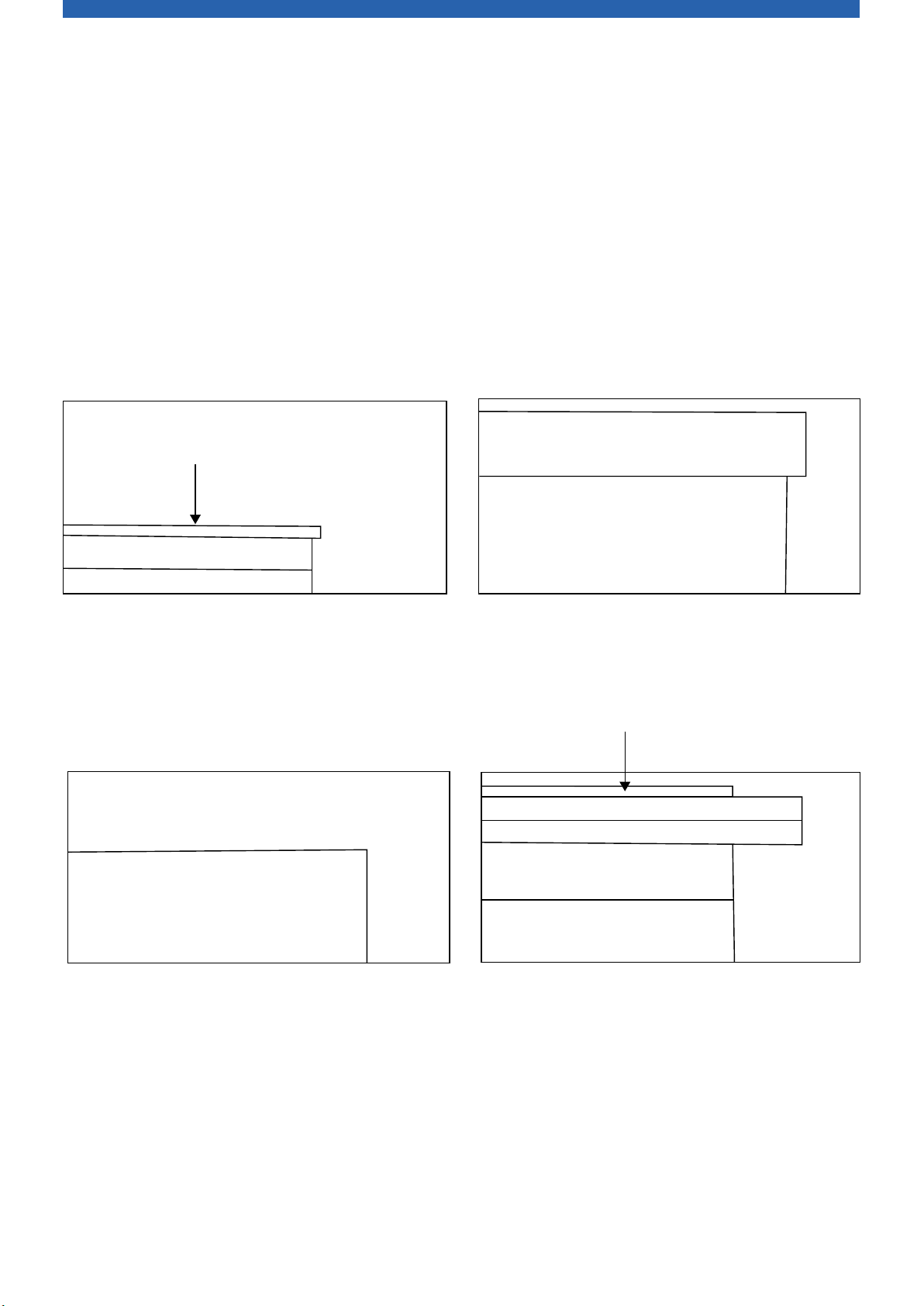
FRAME STRUTS: *SOLID WOOD* 3/4" X 1-1/2" X 60-1/2" 10 pieces
2 pieces
2 pieces
1 pieces
1 pieces
2 pieces
2 pieces
2 pieces
Box of 50
Box of 100
Box of 30
Box of 40
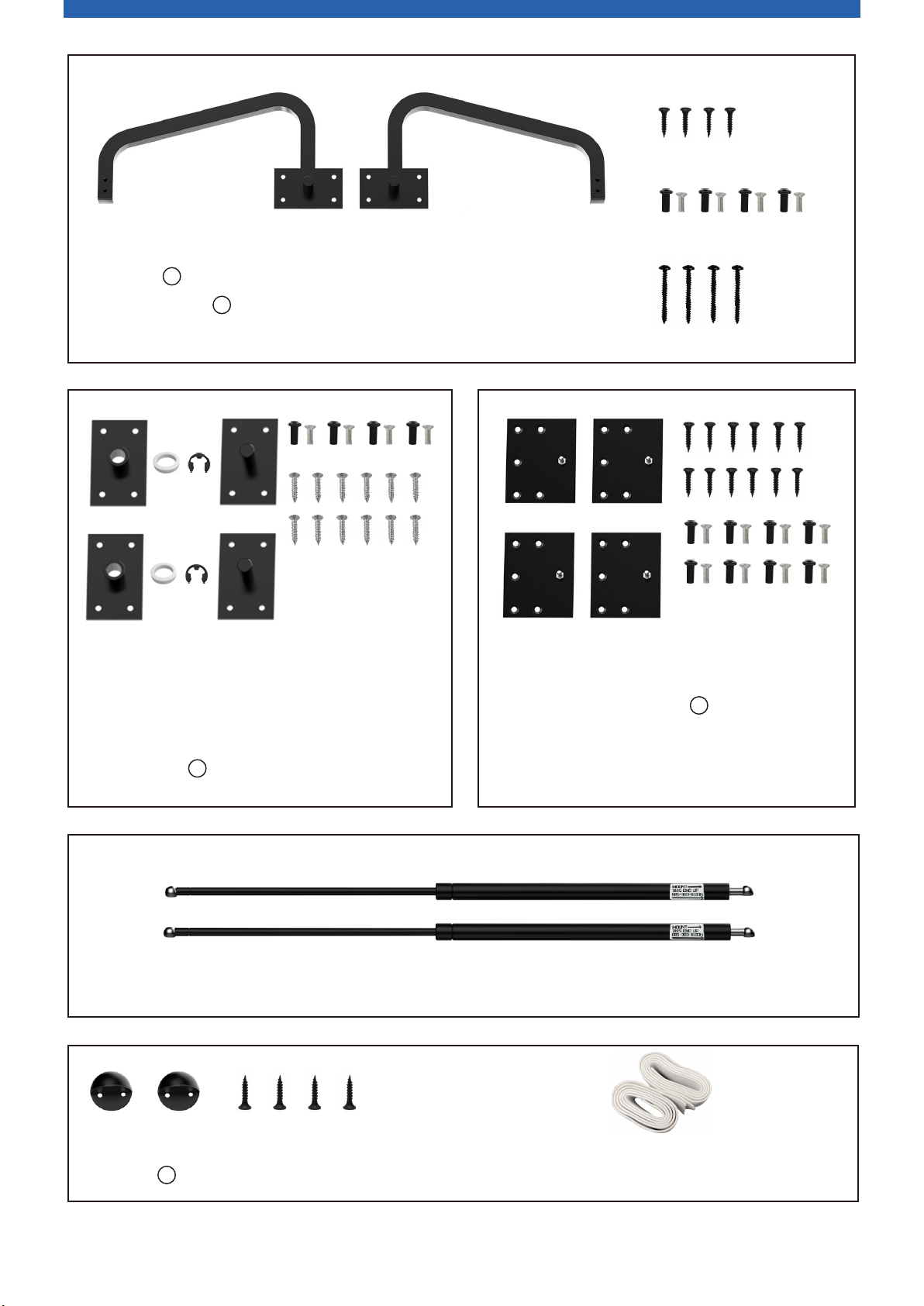
2 HANDLES
Box of 25
1 pieces
2 pieces
1 pieces
1 pieces
1 pieces
1 pieces
3/4" X 1-1/2" X 80"FRAME SIDES: *SOLID WOOD*
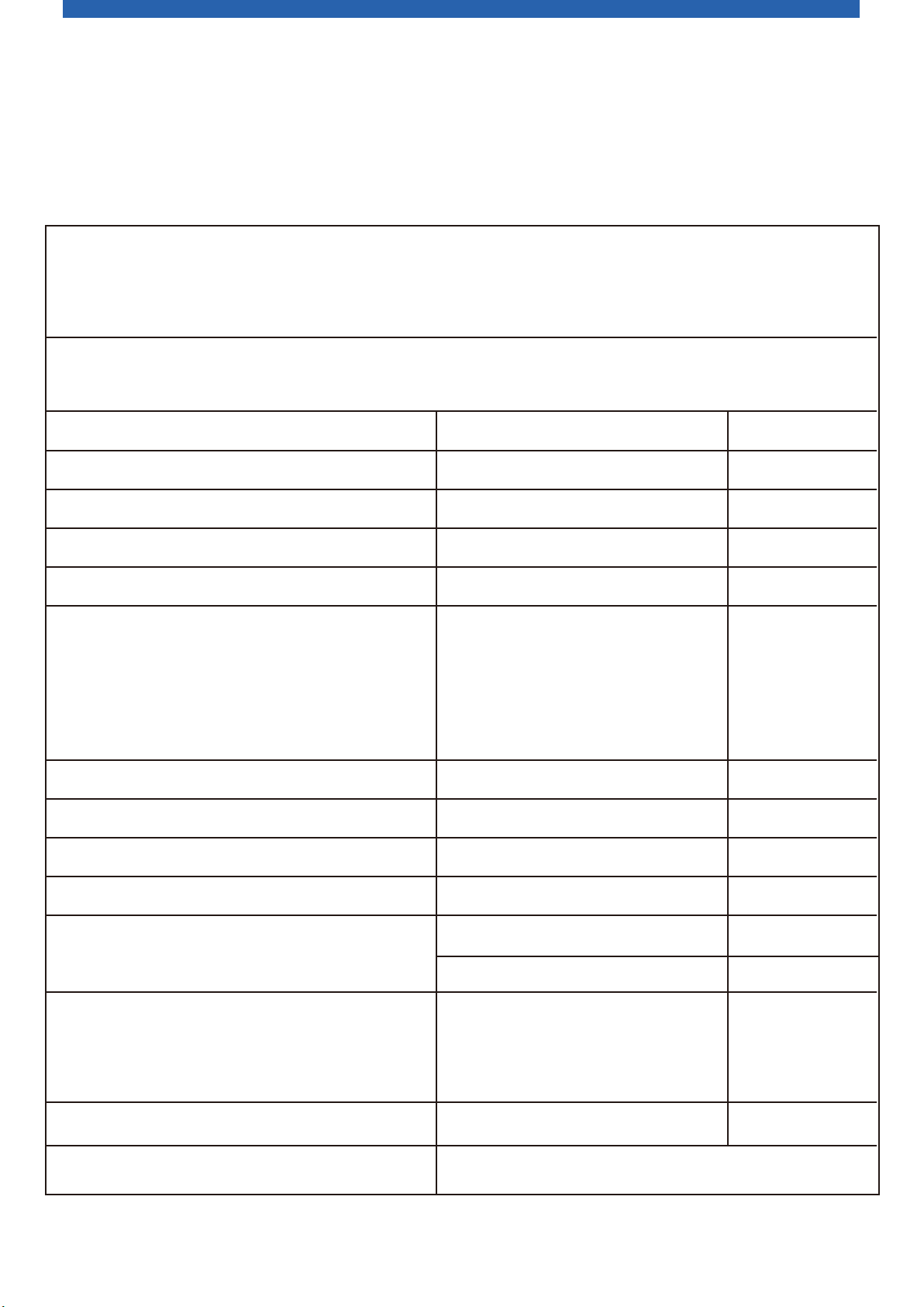
IMPORTANT: PLYWOOD MUST BE USED FOR THESE PIECES:
_B. SIDE RAILS: 3/4" X 5-7/8" X 81-1/2"
3/4" X 3" X 62"
3/4" X 7-7/8" X 62"
3/4" X 32" X 81-3/4"
3/4" X 15-7/8" X 64-3/8"
3/4" X 15-7/8" X 87-1/8"
3/4" X 14-3/8" X 64-3/8"
3/4" X 2-3/4" X 64-3/8"
3/4" X 2-3/4" X 64-3/8"
3/4" X 1-1/2" X 14-3/8"
3/4" X 1-2/5" X 60-1/4"
1/4" X 31" X 80"
13/16" X 80 feet
One 8 ounce bottle
1-1/2"
MUST weigh between 65 - 80 pounds
2"
#8 1-1/4" coarse thread
#8 1-1/2" coarse thread
#8 2" coarse thread
_C. FOOT RAIL:
_D. HEAD RAIL:
_E. BED FACE PANEL:
_F. BED HEADBOARD:
_G. BED CABINET VERTICALS:
_H. BED HEADER:
_l. Leg Support Rail:*SOLID WOOD*
_J. 1/4" PLYWOOD mattress support:
_K. VENEER or MELAMINE TAPE:
_L. WOOD GLUE:
_M. FINISH NAILS:
_N. SCREWS:
_O. DESIRED CABINET HANDLES OR PULLS
_P. MATTRESS
HEADERBOARD:
FRONT RAIL:
REAR RAIL:
MOUNTING CLEATS:*SOLID WOOD*
_A. INNER WOOD BED FRAME:*To be constructed of solid wood: poplar, clear pine, maple, etc.*
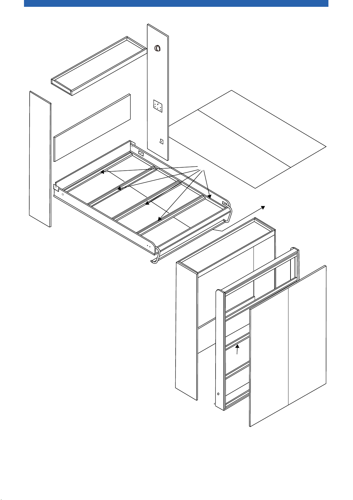
QUEEN SIZE DELUXE KIT VERTICAL BED WITH 3/4"
PLYWOOD FACE PANEL BILL OF MATERIALS / CUT SHEET
Note: Do not substitute other materials.