manuals.online logo
Brands
  1. Home
  2. •
  3. Brands
  4. •
  5. Sauder
  6. •
  7. Indoor Furnishing
  8. •
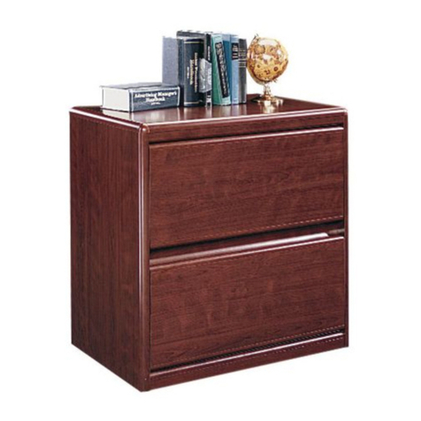
  9. Sauder Via 401443 User manual

Sauder Via 401443 User manual

NOTE: THIS INSTRUCTION
BOOKLET CONTAINS IMPORTANT
SAFETY INFORMATION.
PLEASE READ AND KEEP FOR
FUTURE REFERENCE.
Enlish p 1-20
Français p 21-24
Español p 25-28
Lot # 363349 06/26/14
Purchased: __________________
Be sure to ive us a rin before
makin any returns. 1-800-523-3987
3-Drawer Pedestal
Via Collection | 401443
Need help? Visit Sauder.com to view video assembly tips or chat with a live rep.
Prefer the phone? Call 1-800-523-3987.
Share your journey!
sauder.com
Get all organized
and stu.
Table of Contents Assembly Tools Required
2
3-4
5-20
21-24
25-28
29-30
31
Part Identification
Hardware Identification
Assembly Steps
Français
Español
Safety
Warranty
Hammer
Not actual size
No. 2 Phillips Screwdriver
Tip Shown Actual Size
Skip the power trip.
This time.
401443 www.sauder.com/servicesPae 2
Tape Measure
Part Identification
åWhile not all parts are labeled, some of the parts will have a label or an inked letter on the ede
to help distinuish similar parts from each other. Use this part identification to help identify similar parts.
A2 RIGHT END (1)
B LEFT END (1)
C TOP (1)
D BOTTOM (1)
E BACK (1)
F DRAWER FRONT (1)
K SMALL DRAWER FRONT (2)
P BASE (1)
D78 DRAWER BACK (1)
D87 RIGHT DRAWER SIDE (1)
D88 LEFT DRAWER SIDE (1)
D107 SMALL RIGHT DRAWER SIDE (2)
D108 SMALL LEFT DRAWER SIDE (2)
D109 SMALL DRAWER BACK (2)
D707 SMALL DRAWER BOTTOM (2)
D708 DRAWER BOTTOM (1)
Now you know
our ABCs.
401443www.sauder.com/services Pae 3
A2
B
C
D
E
K
P
D107
D109
D108
D707
F
D87
D78
D88
D708
K
D107
D109
D108
D707
Hardware Identification
åScrews are shown actual size. You may receive extra hardware with your unit.
(EXTENSION SET SHOWN SEPARATED)
EXTENSION RAIL - 2
TEXTENSION SLIDE - 2
UFILE ROD - 2
EE
NON-SWIVEL
CASTER - 2
QSWIVEL
CASTER - 2
R
METAL BRACKET - 3
II SUPPORT PIN - 4
KK
TOUCH-UP PEN - 1
JJ
STWIST-LOCK®
FASTENER - 12
LL SLIDE CAM - 6
PULL - 3
FF
35GA CABINET RIGHT - 2 35GB CABINET LEFT - 2 35GC DRAWER RIGHT - 2 35GD DRAWER LEFT - 2
401443 www.sauder.com/servicesPae 4
Hardware Identification
åScrews are shown actual size. You may receive extra hardware with your unit.
INTERLOCK TRACK - 1
22G
FILE GLIDE - 2
6B
BLACK 9/16" LARGE HEAD SCREW - 22
NN
BLACK 7/8" MACHINE SCREW - 6
MM
PP GOLD 5/16" FLAT HEAD SCREW - 24
20G DRAWER STOP - 3
29G SAFETY STOP - 3
30S BLACK 1-9/16" FLAT HEAD SCREW - 12
401443www.sauder.com/services Pae 5
Step 1 Look for this icon. It means a
video assembly tip is available at
www.sauder.com/services/tips
å Assemble your unit on a carpeted floor or on the empty
carton to avoid scratchin your unit or the floor.
å To bein assembly, push a SAUDER TWIST-LOCK®
FASTENER (S) into the lare holes in the ENDS (A2 and B).
å Repeat this step for the BOTTOM (D) and BACK (E).
401443 www.sauder.com/servicesPae 6
(12 used)
S
Do not tihten the TWIST-LOCK® FASTENERS in this step.
A2
B
Step
401443www.sauder.com/services Pae 7
Step 2
å Insert three SAFETY STOPS (29G) into the holes shown
in the RIGHT END (A2).
This pin must insert
into the location holes
in the RIGHT END (A2).
29G
A2
StepStep 3
401443 www.sauder.com/servicesPae 8
å Diaram 1. Measure 2" from one end of the INTERLOCK TRACK (22G). Position the INTERLOCK TRACK as shown.
å SAFETY STOP / TRACK ATTACHMENT:
Diaram 2. Tilt the first ede of the INTERLOCK TRACK (22G) into the SAFETY STOPS (29G).
å Diaram 3. Rotate the INTERLOCK TRACK and apply force to snap the second ede into the SAFETY STOP.
å Diaram 4. Repeat the SAFETY STOP / TRACK ATTACHMENT for the next SAFETY STOP while holdin the previously
completed SAFETY STOP in its location hole. Repeat these steps until all STOPS have been attached. Visually check that
all INTERLOCK TRACK edes have been snapped into the SAFETY STOPS as shown in diaram 3.
å Diaram 5. Remove the INTERLOCK TRACK assembly from from Diaram 4 and flip it over before insertin the
INTERLOCK TRACK (22G) with SAFETY STOPS (29G) into the roove in the RIGHT END (A2).
Be sure the
interlock track
snaps into each
cabinet actuator.
5.
4.
3.
2.
F
L
I
P
O
V
E
R
2"
1.
22G
29G
29G
22G
Tape Measure
A2
A2
The interlock system is a safety feature
that prevents more than one drawer
from openin at the same time. Do not
use excessive force to open the drawers.
29G
22G
Groove 29G
Step
401443www.sauder.com/services Pae 9
Step 4
å Separate the EXTENSION SLIDES (U) from the
EXTENSION RAILS (T) as shown in the upper diaram
below. Be prepared, the parts are reasy.
å Fasten two EXTENSION RAILS (T) to the ENDS (A2
and B). Use four GOLD 5/16" FLAT HEAD SCREWS (PP).
å NOTE: For each EXTENSION RAIL, turn a SCREW into
the hole shown in the enlared diaram. Then, slide the
innercartride of the EXTENSION RAIL in to find the other
hole that lines up with the hole in the END. Turn a SCREW
into this hole.
Push the black lever in and pull the SLIDE from the RAIL.
Open end
Open end
A2
B
T
T
T
U
After fastening the EXTENSION RAILS to the RIGHT
END (A2), the SAFETY STOPS should touch the top
edge of the RAILS. If the gap is larger than 1/16", the
drawers could lock up and not open. If this happens,
open two drawers at the same time to override the
interlock system. Remove the drawers to re-adjust
the INTERLOCK TRACK assembly.
GOLD 5/16" FLAT HEAD SCREW
(4 used in this step)
PP
Remember:
Rihty tihty.
Lefty loosey.
Step
å Fasten the CABINET RIGHTS (35GA) to the RIGHT END (A2)
and the CABINET LEFTS (35GB) to the LEFT END (B). Use
eiht GOLD 5/16" FLAT HEAD SCREWS (PP) throuh
holes #1 and #3.
å Tap four SUPPORT PINS (KK) into the ENDS (A2 and B).
Step 5
401443 www.sauder.com/servicesPae 10
1
2
3
1
2
3
Roller end
GOLD 5/16" FLAT HEAD SCREW
(8 used in this step)
PP
KK
A2
B
Roller end
After fastening the CABINET RAILS to the
ENDS (A2 and B), the SAFETY STOPS should
touch the top edge of the RAILS. If the gap
is larger than 1/16", the drawers could lock
up and not open. If this happens, open two
drawers at the same time to override the
interlock system. Remove the drawers to
re-adjust the INTERLOCK TRACK assembly.
Step
401443www.sauder.com/services Pae 11
Step 6
å Fasten the BACK (E) and BOTTOM (D) to the LEFT
END (B). Tihten four TWIST-LOCK® FASTENERS.
B
E
D
How to use the SAUDER TWIST-LOCK®FASTENER
1. Insert the dowel end of the FASTENER into the hole of the
adjoinin part.
NOTE: The dowel end of the FASTENER must remain fully
inserted in the hole of the adjoinin part while lockin
the FASTENER.
2. Tihten the FASTENER with a Phillips screwdriver as tiht
as possible.
Dowel end
Roller end
This hole must be here.
Surface with
TWIST-LOCK®
FASTENERS
Surface with
TWIST-LOCK®
FASTENERS
Surface with
TWIST-LOCK®
FASTENERS
Step
å Fasten the RIGHT END (A2) to the BOTTOM (D) and
BACK (E). Tihten four TWIST-LOCK® FASTENERS.
å Fasten the TOP (C) to the ENDS (A2 and B). Tihten four
TWIST-LOCK® FASTENERS.
Step 7
401443 www.sauder.com/servicesPae 12
B
E
D
A2
C
Roller end
These edes should be even.
Surface without
TWIST-LOCK®
FASTENERS
Step
401443www.sauder.com/services Pae 13
Step 8
å Fasten the METAL BRACKETS (II) to the ENDS (A2 and B)
and BOTTOM (D). Use three BLACK 9/16" LARGE
HEAD SCREWS (NN).
å NOTE: Be sure the edes of the METAL BRACKETS are
even with the edes of the ENDS and BOTTOM.
å Fasten the BASE (P) to the ENDS (A2 and B) and
BOTTOM (D). Use three BLACK 9/16" LARGE HEAD
SCREWS (NN) throuh the METAL BRACKETS and into
the BASE.
BLACK 9/16" LARGE HEAD SCREW
(6 used in this step)
NN
B
P
D
A2
II
II
II
Unfinished ede
Step
å Fasten the CASTERS (Q and R) to the BOTTOM (D). Use
sixteen BLACK 9/16" LARGE HEAD SCREWS (NN).
Step 9
401443 www.sauder.com/servicesPae 14
BLACK 9/16" LARGE HEAD SCREW
(16 used in this step)
NN
D
Q
R
The tabs on the NON-SWIVEL
CASTERS (Q) must insert into these holes.
Don't worry. It isn't
Rome. This can be built
in a day.
Step
401443www.sauder.com/services Pae 15
Step 10 VIEW THE T-LOCK BOX VIDEO
å Fasten the DRAWER BACK (D78) to the DRAWER SIDES (D87
and D88). Use four BLACK 1-9/16" FLAT HEAD SCREWS (30S).
å NOTE: Be sure the DRAWER BOTTOM (D708) inserts into the
roove of the DRAWER BACK (D78).
å Repeat this step for the small drawers usin parts K, D107, D108,
D109, and D707.
12
3
å Insert the DRAWER SIDES (D87 and D88) at an anle
into the slot at each end of the DRAWER FRONT (F).
å Slide the DRAWER BOTTOM (D708) into the rooves in the
DRAWER SIDES (D87 and D88) and DRAWER FRONT (F).
The tabs should insert freely
into the slots. Gently tilt the
DRAWER SIDES side to side
until the tabs slip into the slots.
Groove
Start each screw a few turns before
completely tihtenin any of them.
BLACK 1-9/16" FLAT HEAD SCREW
(12 used in this step)
30S
Be sure the DRAWER
BOTTOM inserts into the
DRAWER FRONT roove.
D87
D88
D708
D708
D87
D88
D78
D88
FF
Unfinished
surface
With the palm of
your hand, tap the
DRAWER BOTTOM
down into the roove.
D87
StepStep 11
401443 www.sauder.com/servicesPae 16
å Insert a SLIDE CAM (LL) into the LEFT DRAWER SIDE (D88).
å Fasten an EXTENSION SLIDE (U) to the LEFT DRAWER
SIDE (D88). Use two GOLD 5/16" FLAT HEAD
SCREWS (PP) throuh holes #1 and #4.
å NOTE: The screw head in the CAM must be visible throuh
the slotted hole in the SLIDE.
å Repeat this step for the small drawers usin the DRAWER
LEFTS (35GD) on the SMALL LEFT DRAWER SIDES (D108).
å NOTE: The roller end on the DRAWER LEFT should be
toward the back of the drawer.
å NOTE: Use holes #1 and #3 in each DRAWER SLIDE.
U
LL
4
Screw head - turn CAM to line up holes in
the SLIDES with holes in DRAWER SIDES
1
2
3
D88
GOLD 5/16" FLAT HEAD SCREW
(6 used in this step)
PP
Open end
Step
401443www.sauder.com/services Pae 17
Step 12
å Flip the drawer over onto the LEFT DRAWER SIDE (D88).
å Insert a SLIDE CAM (LL) into the DRAWER RIGHT SIDE (D87).
å Diaram 1. Insert the tabs on a DRAWER STOP (20G) into the slots in a EXTENSION SLIDE (U). You may need to insert
one tab first, then the other.
å Diaram 2. Visually check that the DRAWER STOP (20G) is seated in the SLIDE (U).
å Diaram 3. If the DRAWER STOP is not seated, use your hammer to ently tap the SLIDE until the tabs are properly seated
in the slots.
å Now, fasten the EXTENSION SLIDE (U) to the DRAWER RIGHT SIDE (D87). Use two GOLD 5/16" FLAT HEAD SCREWS (PP).
å Repeat this step for the small drawers usin the DRAWER RIGHTS (35GC)
on the SMALL RIGHT DRAWER SIDES (D107).
20G
U
2. 3.
Post
LL
Screw head - turn CAM to
line up holes in the SLIDES
with holes in DRAWER SIDES
U
4
1
2
3
D88
D87
GOLD 5/16" FLAT HEAD SCREW
(6 used in this step)
PP
1.
20G
U
These tabs must
insert into the slots.
Slot
Open end
StepStep 13
401443 www.sauder.com/servicesPae 18
BLACK 7/8" MACHINE SCREW
(6 used in this step)
MM
å Fasten a PULL (FF) to the DRAWER FRONT (F). Use two
BLACK 7/8" MACHINE SCREWS (MM).
å Repeat this step for the small drawers.
å Push a FILE GLIDE (6B) onto the RIGHT DRAWER SIDE (D87).
å Slide the FILE RODS (EE) into the FILE GLIDE (6B) on the
RIGHT DRAWER SIDE (D87)
å Slide another FILE GLIDE (6B) onto the other end of the
FILE RODS (EE), then press this FILE GLIDE over the
LEFT DRAWER SIDE (D88).
Insert the FILE RODS into the holes
of your choice in the FILE GLIDES,
dependin on your file sizes.
6B
EE
D88
FF D87
F
EE
6B
Step
401443www.sauder.com/services Pae 19
Step 14
å Carefully stand your unit upriht.
å To insert the lare drawer into your unit, line up the
EXTENSION SLIDES on the drawer with the EXTENSION
RAILS on the unit and push the drawer into the unit until
the drawer is fully inserted. The drawer will push in hard
until it is all the way in, then it will slide in and out easier.
å To insert the small drawers into your unit, tip the front
of the drawer down and drop the rollers on the drawer
behind the rollers on the unit. Lift the front of the drawer
up and slide it into the unit.
å For lon-term care and maintenance of your unit, you
may touch up the edes with the TOUCH-UP PEN (JJ).
Pro Tip: Lift with your
les. And, you know,
your arms.
30 lbs.
30 lbs.
10 lbs. each in the
small drawers
JJ
Step
å To make adjustments to the drawers, loosen SCREW #3 in the SLIDES a 1/4 turn, then turn the cam clockwise or
counter-clockwise. Notice how the drawer raises or lowers as you turn the cam. By adjustin the drawers this way, it will
help the DRAWER FRONT line up better when closed. Tihten the SCREWS when finished with adjustments.
å NOTE: Loosen SCREW #4 in the EXTENSION SLIDE in the bottom drawer.
å NOTE: Please read the back paes of the instruction booklet for important safety information.
å This completes assembly. Clean with your favorite furniture polish or a damp cloth. Wipe dry.
Step 15
401443 www.sauder.com/servicesPae 20
And to celebrate, why not share your success story?
The hiher the screw in the oblon hole,
the hiher your drawer front will be. The
lower the screw, the lower the drawer front.
Loosen screw #3 a 1/4 turn, turn the cam a 1/4 turn
maximum in both the clockwise and counter-clockwise
directions to make adjustments, and then tihten screw #3.
Cam

Other Sauder Indoor Furnishing manuals

Sauder Costa Credenza 422984 User manual

Sauder

Sauder Costa Credenza 422984 User manual

Sauder 420406 User manual

Sauder

Sauder 420406 User manual

Sauder Tremont Row 427968 User manual

Sauder

Sauder Tremont Row 427968 User manual

Sauder Cannery Bridge 415910 User manual

Sauder

Sauder Cannery Bridge 415910 User manual

Sauder Cannery Bridge 420374 User manual

Sauder

Sauder Cannery Bridge 420374 User manual

Sauder Coral Cape 423808 User manual

Sauder

Sauder Coral Cape 423808 User manual

Sauder Whitaker Point 429369 User manual

Sauder

Sauder Whitaker Point 429369 User manual

Sauder 427470 User manual

Sauder

Sauder 427470 User manual

Sauder 429430 User manual

Sauder

Sauder 429430 User manual

Sauder 418269 User manual

Sauder

Sauder 418269 User manual

Sauder 425024 User manual

Sauder

Sauder 425024 User manual

Sauder 414764 User manual

Sauder

Sauder 414764 User manual

Sauder Englewood 426484 User manual

Sauder

Sauder Englewood 426484 User manual

Sauder Barrister Lane Storage Credenza 414721 User manual

Sauder

Sauder Barrister Lane Storage Credenza 414721 User manual

Sauder Lateral File 419606 User manual

Sauder

Sauder Lateral File 419606 User manual

Sauder beginnings 413324 User manual

Sauder

Sauder beginnings 413324 User manual

Sauder Adept Storage 418141 User manual

Sauder

Sauder Adept Storage 418141 User manual

Sauder 412267 User manual

Sauder

Sauder 412267 User manual

Sauder Parklane Series User manual

Sauder

Sauder Parklane Series User manual

Sauder Via 419708 User manual

Sauder

Sauder Via 419708 User manual

Sauder Carson Forge Collection 415117 User manual

Sauder

Sauder Carson Forge Collection 415117 User manual

Sauder 408726 User manual

Sauder

Sauder 408726 User manual

Sauder 413322 User manual

Sauder

Sauder 413322 User manual

Sauder OfficeWorks AFFIRM 427414 User manual

Sauder

Sauder OfficeWorks AFFIRM 427414 User manual

Popular Indoor Furnishing manuals by other brands

Coaster 121181 B1 Assembly instructions

Coaster

Coaster 121181 B1 Assembly instructions

Whalen WMCXL-2 manual

Whalen

Whalen WMCXL-2 manual

Argos Puerto Rico 658/3129 Assembly instructions

Argos

Argos Puerto Rico 658/3129 Assembly instructions

FURNITUREBOX COMBI 3 Assembly instruction

FURNITUREBOX

FURNITUREBOX COMBI 3 Assembly instruction

World Market Kamron Windsor 601058 Assembly instructions

World Market

World Market Kamron Windsor 601058 Assembly instructions

Powell 697-432T2 Assembly instructions

Powell

Powell 697-432T2 Assembly instructions

convenience concepts MILAN 227650 Assembly instructions

convenience concepts

convenience concepts MILAN 227650 Assembly instructions

Office Star Products EM59722 operating instructions

Office Star Products

Office Star Products EM59722 operating instructions

namesake Crewe 22286 Care and maintenance

namesake

namesake Crewe 22286 Care and maintenance

Honey Can Do GAR-01121 Assembly instructions

Honey Can Do

Honey Can Do GAR-01121 Assembly instructions

LAMS 700630 quick start guide

LAMS

LAMS 700630 quick start guide

Teknion Transit KSB Installation guides

Teknion

Teknion Transit KSB Installation guides

American Standard YORKVILLE 3120.019 Specification sheet

American Standard

American Standard YORKVILLE 3120.019 Specification sheet

Palace Imports 5661 Assembly instructions

Palace Imports

Palace Imports 5661 Assembly instructions

Furniture of America YNJ-17906C17 Assembly instructions

Furniture of America

Furniture of America YNJ-17906C17 Assembly instructions

nardi CLIP 70 manual

nardi

nardi CLIP 70 manual

WENATEX Wenaflex Premium M operating instructions

WENATEX

WENATEX Wenaflex Premium M operating instructions

Broyhill ASHEVILLE GB22-813 Assembly instructions

Broyhill

Broyhill ASHEVILLE GB22-813 Assembly instructions

manuals.online logo
manuals.online logoBrands
  • About & Mission
  • Contact us
  • Privacy Policy
  • Terms and Conditions

Copyright 2025 Manuals.Online. All Rights Reserved.