Ropox Slimline Electric 40-15601 User manual

Ropox SlimLine Electric
User Manual
This manual must always accompany the product.
TF 200.01.0028
28-07-2022

TF 200.01.0028_eng 1
Table of contents
1. Symbols used in this manual..................................................................................................................... 2
2. General safety ........................................................................................................................................... 2
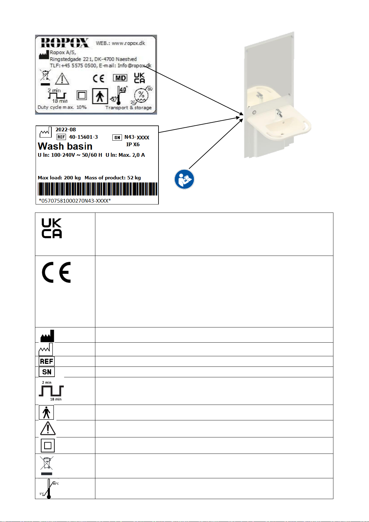
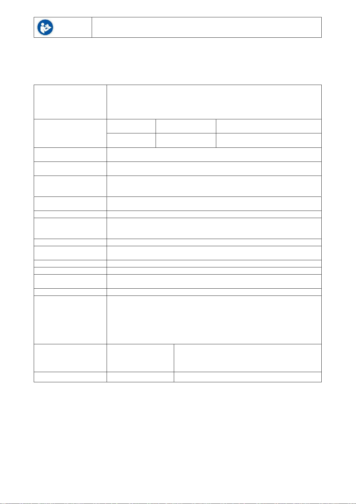
2.1 Product Unit label .............................................................................................................................. 4
3. General requirements................................................................................................................................ 5
3.1 Product information.................................................................................................................................. 5
3.2 Product description.................................................................................................................................. 5
3.3 Intended use............................................................................................................................................ 5
3.4 Intended operator .................................................................................................................................... 6
3.5 Essential Performance............................................................................................................................. 6
3.6 Non-clinical functions............................................................................................................................... 6
3.7 Clinical functions...................................................................................................................................... 6
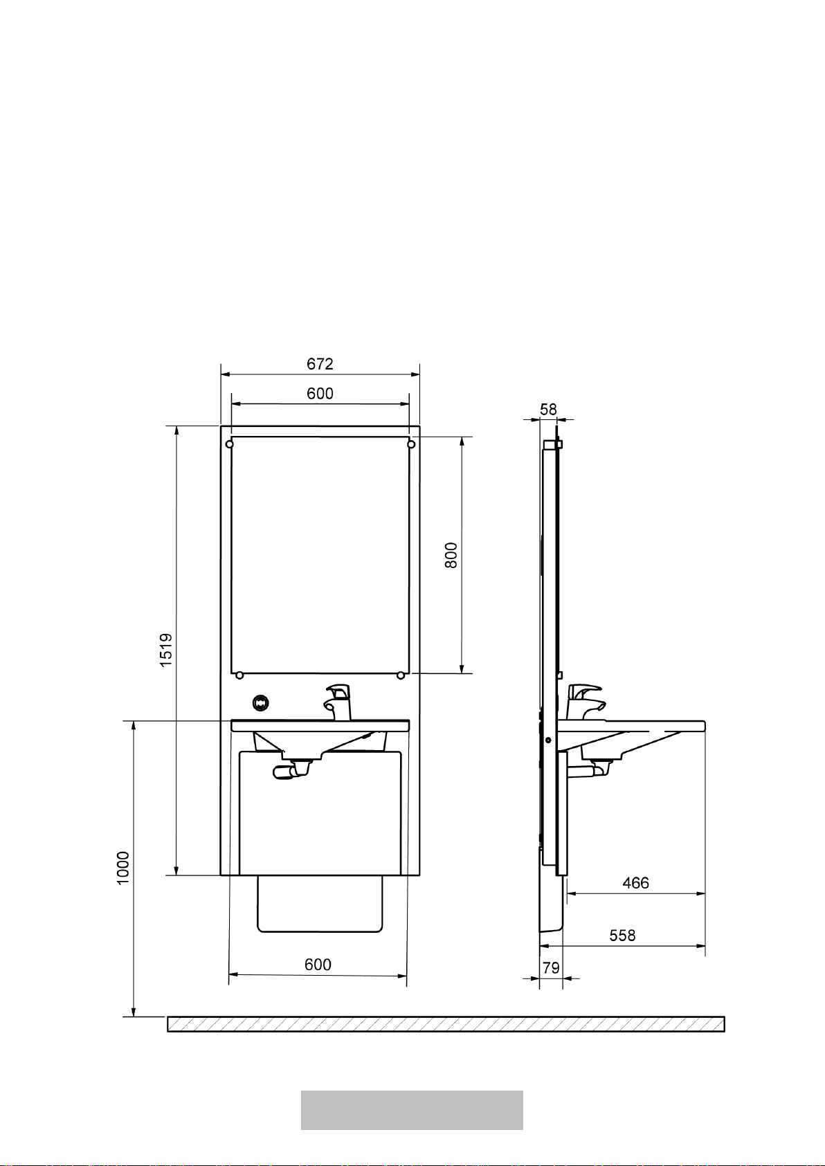
3.8 Product dimensions................................................................................................................................. 6
4. Instructions for use .................................................................................................................................... 7
4.1 Operating the product.............................................................................................................................. 7
4.2 Installation interfaces............................................................................................................................... 9
4.3 Connection adapters.............................................................................................................................. 10
4.4 Installation of product............................................................................................................................. 11
4.4.1 List of components.......................................................................................................................... 11
4.4.2 Installation of product...................................................................................................................... 13
4.4.3 Functionality test............................................................................................................................. 22
4.5 Cable diagrams...................................................................................................................................... 22
5. Trouble shooting...................................................................................................................................... 23
6. Safety in use............................................................................................................................................ 23
7. Cleaning................................................................................................................................................... 24
7.1 Preapproved cleaning agents.......................................................................................................... 24
8. Maintenance ............................................................................................................................................ 24
8.1 Performance test ................................................................................................................................... 24
8.2 Service schedule ................................................................................................................................... 25
9. Spare parts list......................................................................................................................................... 26
10. Environmental protection..................................................................................................................... 27
11. Electromagnetic compatibility.............................................................................................................. 27
11.1 Suitable Environments..................................................................................................................... 27
11.2 Adjacent and stacked use................................................................................................................ 27
11.3 Cables.............................................................................................................................................. 27
11.4 RF portable equipment.................................................................................................................... 27
12. Complaints........................................................................................................................................... 28

TF 200.01.0028_eng 2
1. Symbols used in this manual
Warning Symbol
Indication of potentially hazardous situation. If not avoided, it can result in serious injury or
death.
Caution Symbol
Indication of potentially hazardous situation which may result in minor or moderate injury.
It may also be used to alert against unsafe practices.
Notification Symbol
This symbol is used to notify correct use and handling of the product.
2. General safety
This manual must be read and understood before use.
Always keep this manual in close proximity of the product.
The use, installation and service of this product must be in
compliance with this manual to avoid accidents and serious
personal injury.
Never use or handle this product in other ways specified in
this manual as it can result in personal safety hazards and/or
cause damage to the product.
Persons installing and/or using this product either as operator
or user should have the necessary safety information and
access to this manual.
If the supply cord is damaged, it must be replaced by the
manufacturer, its service agent or similarly qualified
designated persons in order to avoid a hazard.

TF 200.01.0028_eng 3
Do not perform repairs, disassembly or assembly operations,
add-ons, re-adjustments or modification of the product
beyond what is described in this manual. These must be
carried out by Ropox or Ropox authorized personnel. Do not
perform service while in use.
This appliance can be used by children aged from 8 years
and above and persons with reduced physical, sensory or
mental capabilities or lack of experience and knowledge if
they have been given supervision or instruction concerning
use of the appliance in a safe way and understand the
hazards involved. Children shall not play with the appliance.
Cleaning and user maintenance shall not be made by
children without supervision.
Do not use the product if it has defects or have become
damaged before being repaired or replaced.
If the control box makes unusual noise or smells, switch off
the mains voltage immediately.
Take care that the cables are not damaged.
Unplug the mains cable on mobile equipment before it is
moved.
The products must only be used in an environment that
corresponds to their IP protection.
The information in this manual is based on correct installation
in accordance with installation instructions for this product.
Ropox cannot be held liable if the product is used in any way
that differs from stated in this manual and/or installation
instruction.
Ropox reserve the right to amend this manual and reference
documents without prior notice.

TF 200.01.0028_eng 4
2.1 Product Unit label
This product is UKCA-marked in accordance with:
UK SI 2002 No. 618 - The Medical Devices Regulations 2002, and its amendments
UK SI 2008 No. 1597 - The Supply of Machinery (Safety) Regulations 2008, and its
amendments
This product is CE-marked in accordance with:
European Medical Device Directive 93/42/EEC, including
amendments incorporated in Directive 2007/47/EEC.
European Medical Device Regulation (EU)2017/745
Council Directive 2006/42/EC on machinery
Council Directive 2011/65/EU, RoHS
Manufacturer name and address
Date of production
Stock number
Serial number
Operating interval of electrically operated equipment. The use of electrical height
adjustable equipment can run at maximum 2 minutes, followed by an 18-minute
break.
Type BF applied part. The product complies with IEC 60601-1 requirements to
provide protection against electric shock.
Consult manual for important safety related information, warnings and safety
precautions.
Class II, double isolated electrical components.
Do not dispose as unsorted municipal waste. Product must be returned to a
designated recycling station.
Operating and storing temperatures may not exceed 5-40C°
Ropox SlimLine Washbasin Complete
Electric, 60cm support, 67cm unit

TF 200.01.0028_eng 5
3. General requirements
3.1 Product information
Manufacturer
Product models
Part number
Model
Configuration
40-15601
SlimLine Complete
Straight Support Washbasin
Expected service life
5 years
MDR Class
2017/745
Class I
Applied part
classification
60601-1
Type BF applied part
MEE Class
60601-1
Class II
Height adjustment
70-100cm
Maximum user weight
according to DS/EN
17966:2016
200kg
Power supply
230V ~50Hz
I in
Max 2.5A
Intermittence
2min use / 18min pause
IP rating
IPX6
Ambient temperature
range
-10 °C to +50 °C Transport and storage
+5 °C to +45 °C Operation
Relative humidity:
20% to 80% - non-condensing
Intended environments
This product is to be used only in:
Professional Healthcare Environment
Homecare Environment
The device is not intended for use in special environments as defined by IEC
60601-1-2
Materials in contact
with patient
Washbasin
Cover plate
Synthetic/marble composite
Vacuum-formed acrylic glass
Accessories
40-15630
Hand control with holder
3.2 Product description
The height-adjustable SlimLine unit is characterized by the elegant and slim design that combines mirror and
washbasin into one solution. Ranging from 70-100cm in height adjustment, it offers excellent access for both
standing and seated users. In addition, it is designed with plenty of legroom underneath the sink, allowing
wheelchair users to come close to the washbasin and within easy reach of the mixer tap.
3.3 Intended use
The SlimLine washbasin combines mirror and basin in one unit, and the mirror is therefore always at the right
height no matter if you are sitting in a wheelchair or standing up. You adjust the height with a push on the
control switch which is always within reach as it is located right under the mirror.
Consult manual before use

TF 200.01.0028_eng 6
3.4 Intended operator
Reading and understanding this manual will be sufficient training for an intended operator. Children under
the age of 16 or patient are not considered intended operator.
3.5 Essential Performance
The product does not have essential performance, as the patient and user do not experience any risk in case
of loss of product function/performance.
3.6 Non-clinical functions
Height adjusting offers better ergonomics to the user.
3.7 Clinical functions
The product does not have any clinical functions.
3.8 Product dimensions
All dimensions in mm

TF 200.01.0028_eng 7
4. Instructions for use
4.1 Operating the product
Ropox SlimLine is adjusted in height by using either the fixed control, or the hand control with spiral cable
(accessory). This ensures an optimal height for washing your hands, aiding users and carers alike.
Ropox SlimLine is NOT for use as a lifting table or person lift.
Height adjustment with a fixed standard control
Hand control with spiral cable (available for purchase)

TF 200.01.0028_eng 8

TF 200.01.0028_eng 9
4.2 Installation interfaces
Construction
The wall must be made of a material suited for screw mounting
and approved for damp rooms. The hatched area is the minimum
area for reinforcement of the wall.
Tested in accordance with DS/EN 12182:2012 and DS/ISO
17966:2016 with the following max. user weights:
40-15601: 165kg (363 lbs)
40-15605: 120kg (265 lbs)
40-15607: 200kg (440 lbs) (when using a porcelain wash basin)
Max. tensile load of upper screws
68kg/screw (150 lbs)
The washbasin is supplied with a set of screws and rawlplugs
suitable for mounting on a concrete wall. The fitter should always
consider the material, condition and strength of the wall and use
screws and rawlplugs suitable for the specific wall type.
Plumbing
The drain is Ø32 (1 ¼”) and ends in an Ø32x88.5° drain
elbow.
The water supply ends in 2 (two) 90° shut-off valves with
½” outside thread pointing downwards in an angle of 45°
(not included). The maximum protrusion of the shut-off
valves and drain connection should be max 77mm (3”) to
allow for the covers.
The optimum location and orientation are as shown.
It is important that all hoses for water connection and drain
are flexible to allow the frame to move freely within the
height-adjustment range of 700-1000mm (27 1/2” – 39
2/5”) (including washbasin). If a different location of water
supply from the recommended positioning is required and
if there is a floor drain, the installation cover (40-15610)
can’t be used.
For purchase of adapters for connection to various
standard installations, see ”Connection Adapters –Other
Washbasins”.
Power
Recommended location of socket in wall for optimum and
hidden wiring is above unit as shown. The cable from the
control unit is 2000mm (78”).
Electrical socket is
placed in a radius of
1500mm from the
shown position

TF 200.01.0028_eng 10
4.3 Connection adapters
If the recommendations cannot be met, the components described below may be ordered. Ropox is not
responsible for the optimal functionality of the below components under covers when adjusting the height of
the unit.
Water connection adapters
Hoses from washbasin
Adapter
Installation in room
(not included)
No adapter needed
1/2"
Thread
1/2" -> 3/8"
Item no. 97001670
3/8"
Thread
1/2" -> 15mm
Item no. 97001666
15mm
Pipe
Water hose extensions
Hose from washbasin
Coupling piece
Extra hose
1/2" -> 1/2"
Item no. 97001662
1/2" x 1/2", 0.5m, steel
Item no. 97001123
1/2" x 1/2", 1m, plastic
Item no. 97001120
Drain adapters
Drain from washbasin
Adapter
Installation in
room (not included)
No adapter needed
Ø32
Ø32 -> Ø40
Item no. 97001660
Ø40
Ø32 -> Ø50
Item no. 97001661
Ø50
Drain extensions
Drain hose from washbasin
Coupler
Extra drain hose
Ø32-Ø32
Item no. 97001662
Ø32 Flex hose, 40-110cm
Item no. 97001161
Ø32 Flex hose, 27-62cm
Item no. 97001162
1/2”
Ø32
Ø32

TF 200.01.0028_eng 11
4.4 Installation of product
Warning!
The product should always be able to travel the full range of actuation without colliding with
objects. Failing to do so will compromise the product stability.
Warning!
The fitter should always consider the material, condition and strength of the wall and use
screws and rawlplugs suitable for the specific wall type.
Prior to the installation, make sure that all parts have been provided in accordance with the list of
components.
4.4.1 List of components
40*15601-040
Lifting unit
1x
97002454
Mirror 600x800x5
1x
40*15601-084
Cover top
1x
40*45601-062
Cover bottom
1x
40-15610
Installation cover
1x
97002671
Actuator
1x

TF 200.01.0028_eng 12
97002674
Fixed control
1x
97002672
Control box
1x
97002679
97002680
Power supply
AC cable 2m
1x
1x
97001706
Oras Saga 3910F
1x
40-15612-0
Incl.
97001601
97001162
97001035
97001126
97001605
95091070
Plumbing kit SlimLine
Prevex siphon
Flexible drain hose Ø32/32 pipe
32x88,5° white PP Wafix elbow HT
Connection hose 700mm, Lindner
Prevex 100mm extension
Plate screw Ø4,8x70 cross recess A2
1x
1x
1x
1x
2x
1x
1x
40*15601-100
Incl.
95027578
95027576
95125035
40-44170-1
96000170
40*15601-021
95061290
95170512
97001467
40*15601-095
95020521
Mounting parts SlimLine frame
Frame screw 7,5x72 stainless
Zebra ”shark” dowel 10x61
Chipboard screw 5x35
Mirror bracket
Strips black 4,8/290mm
Mounting bracket
Bolt M12x90
Chamfered washer M12
Mounting parts for Ifö Spira 60
Spacer
CSK INSEX screw M5x20
1x
8x
8x
3x
1x
4x
1x
2x
2x
1x
8x
4x
97001582
60 cm Straight Support Washbasin
1x

TF 200.01.0028_eng 13
4.4.2 Installation of product
The maximum tensile load of the screws is 68 kg. The wall must be able to resist such tensile load.
Fix the mounting bracket as illustrated on the drawing with the right distance to water and drain.
Make sure that the mounting bracket is level.
Hang the lifting unit on the mounting bracket.
Make sure to put the M12 bolts for the washbasin in the frame prior to mounting.
M12 bolts mount from behind,
before mounting the frame on the
wall

TF 200.01.0028_eng 14
Place the unit in accordance with the water connection and drain as shown on the drawing.
Push 8 spacers in behind the frame so that it has the right distance to the wall.
Mark the 8 holes for fastening. Take the lifting unit down again and drill the holes in the wall.
Centerhole for
mountingbraket

TF 200.01.0028_eng 15
Use suitable rawlplugs and screws for the mounting.
Remove the protective foil on the tape and fasten the power supply above the unit. Locate 1.5 m above
the floor measured on the underside. Place it in the middle of the lifting unit.
1.5m above floor

TF 200.01.0028_eng 16
Mount the control box on the mounting bracket. Make sure that the small aluminium leg interlocks and
locks the box in a fixed position.

TF 200.01.0028_eng 17
Connect the electrical system as illustrated. Fix the excess cable from the power supply on the mounting
bracket with strips.
Check that the unit freely moves at up/down. If needed, use cable clips etc. for the power cable.
Fix the rods for the mirror bracket in the frame with M5 countersunk screws.

TF 200.01.0028_eng 18
Install the siphon. Adjust the holder bracket to 20mm.
Mount the flat cover and 3 (three) mirror brackets so it is kept in.

TF 200.01.0028_eng 19
Now mount the washbasin with the enclosed mounting parts for bolt mounted washbasins.
Caution!
When mounting a porcelain washbasin, an insolation foam pad MUST be placed between
the washbasin and the unit. It is recommended to grout around the washbasin.
Remove the protective foil from the double-coated tape on the back of the brackets for the installation
cover.
That is now pushed in place so that the brackets glue to the wall.
Other manuals for Slimline Electric 40-15601
1
Table of contents
Other Ropox Plumbing Product manuals
Popular Plumbing Product manuals by other brands

Toto
Toto NEOREST TBXM1A V300 installation guide

Spectrum
Spectrum Pfister Brea LF-042-BR Maintenance & Care Guide

baliv
baliv WT-600 manual

Blanco
Blanco 10 Triple Bowl Undermount 513-690 Specifications

METHVEN
METHVEN echo Basin Mixer installation guide

Triton
Triton VALDI Installation and operating instructions

Pressalit
Pressalit R9113 Mounting instruction

Toto
Toto TBV01101U Installation and owner's manual

Glacier bay
Glacier bay HD67579W-6201 Installation and care guide

Brizo
Brizo Trevi Cross 6516829 Series manual

Moen
Moen TS9041 quick start guide

Lefroy Brooks
Lefroy Brooks X1-2040 Installation, operating, & maintenance instructions