Ropox VanityLine User manual

Ropox VanityLine Washbasin Electric
User Manual
Mounting Instructions
Keep this folder with product at all times!
PDF 6174 / 25.10.2017
PA 2004 00634
© ROPOX 2017

Page 2
© ROPOX 2013
Contents
1. INTRODUCTION....................................................................................................................................................3
2. COMPLIANCE WITH EU-DIRECTIVES ...........................................................................................................3
3. APPLICATION........................................................................................................................................................3
3.1 Control switch........................................................................................................................................................4
4. TECHNICAL DATA VANITYLINE WASHBASIN............................................................................................5
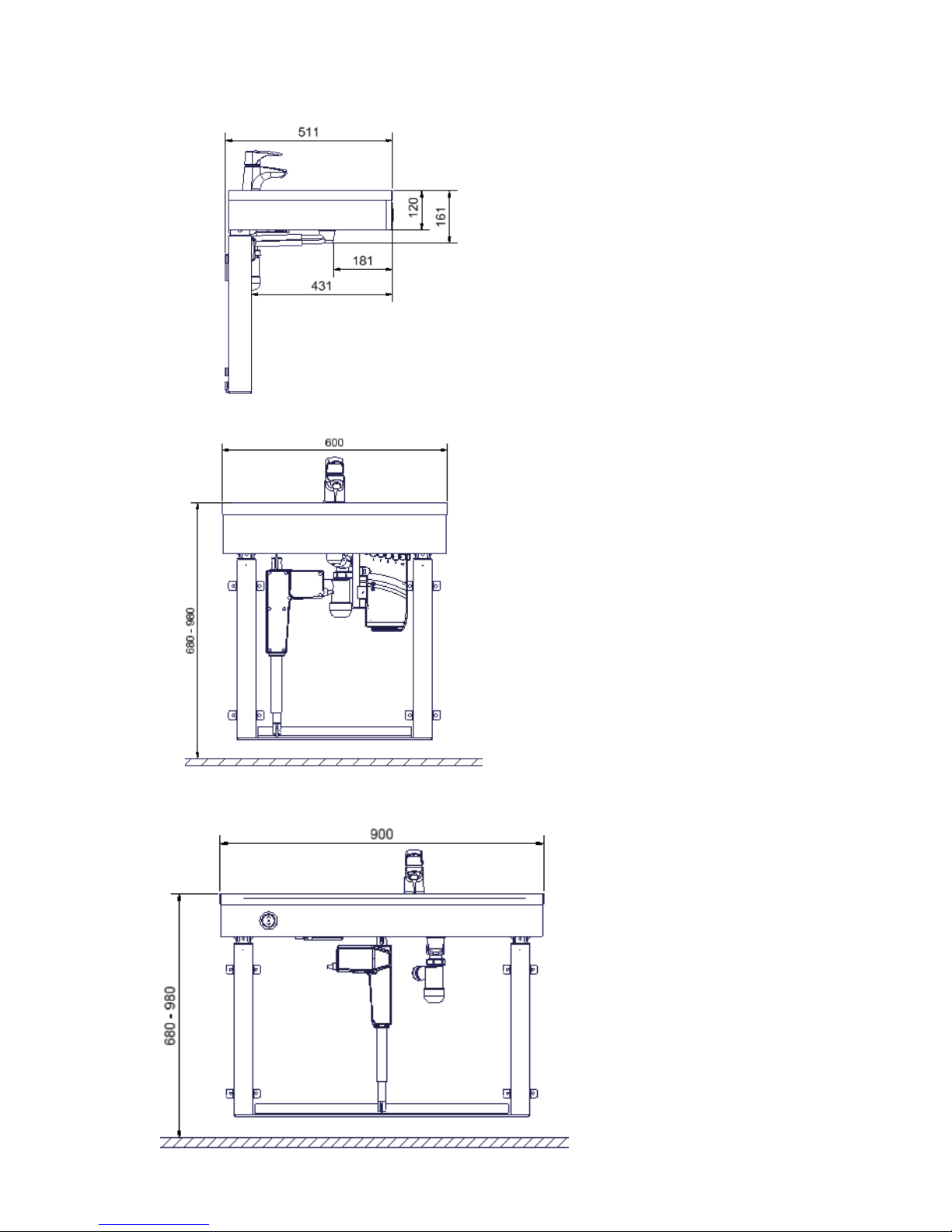
5. DIMENSIONSSKETCH .........................................................................................................................................6
6. SUPPLY POINTS, WATER SUPPLY AND WASTE..........................................................................................7
6.1 Connection adapters .........................................................................................................................................11
7. MOUNTING INSTRUCTIONS............................................................................................................................12
7.1 Mounting of frame ............................................................................................................................................12
7.2 Mounting of frame on the wall ..........................................................................................................................12
7.3 Mounting of spacers..........................................................................................................................................13
7.4 Mounting of actuator........................................................................................................................................14
7.5 Mounting of top frame.......................................................................................................................................14
7.6 Mounting of wooden fascias.............................................................................................................................15
7.7 Mounting of control switch...............................................................................................................................16
7.8 Mounting of control unit...................................................................................................................................17
7.9 Wiring circuit....................................................................................................................................................18
7.10 Mounting of washbasin ....................................................................................................................................20
7.11 Mounting of water supply and waste................................................................................................................21
8. MOUNTING OF ACCESSORIES .......................................................................................................................21
8.1 Mounting of safety strip....................................................................................................................................22
8.2 Mounting of hand control.................................................................................................................................24
8.3 Mounting of infrared control............................................................................................................................24
8.4 Pre-setting of maximum water temperature .....................................................................................................24
8.5 Mounting of cover plates ..................................................................................................................................25
8. LIST OF COMPONENTS FOR VANITYLINE WASHBASIN........................................................................27
11. OPTIONS................................................................................................................................................................31
12. SAFETY IN USE....................................................................................................................................................32
13. CLEANING/ MAINTENANCE............................................................................................................................33
13.1 Cleaning, frame ...........................................................................................................................................33
13.2 Cleaning, washbasin....................................................................................................................................33
13.3 Maintenance.................................................................................................................................................33
13.4 Service schedule, operation and maintenance.............................................................................................34
14. TROUBLE SHOOTING........................................................................................................................................35
15. SPARE PARTS.......................................................................................................................................................36
16. CE-MARKING.......................................................................................................................................................37
17. COMPLAINTS.......................................................................................................................................................38

Page 3
© ROPOX 2013
1. Introduction
The VanityLine washbasin is electrically height-adjustable from 68-98 cm to obtain optimum working
height. Wheelchair users have unimpeded space up to the wall for better access.
If you have chosen the electrical version, frequent height adjustment can be made through activation
of the control switch on the front fascia of the washbasin. As an option large press pads and remote
control are available on request.
The users of the product must follow these instructions. It is imperative that the instructions have
been read and understood before operation of the product.
The instructions should always be available to the user and accompany the product in the case of
relocation.
The correct use, operation and inspection are decisive factors for efficient and safe performance.
2. Compliance with EU-directives
This product has CE marking and therefore meets the basic requirements concerning performance
and safety of the current Machinery Directive. All types of the Ropox VanityLine washbasins are
made in accordance with the relevant requirements of the Medical Devices Directive No. 93/42/EEC
and are all in the lowest risk class 1.
See separate CE-declaration, page 37.
3. Application
The VanityLine washbasin is adjustable in height in order to obtain optimum working height for user
and helper. Do NOT use VanityLine washbasin as a lifting table or person lifter.
The product should be used indoor, at temperatures and humidity as described in section 4
The control unit complies with IP66 and must always be installed in accordance with the
national Heavy Current Regulations or corresponding national or international standards.
This document must ALWAYS be kept with the product and have been read and
understood by the user.
If this product is electrically adjustable in height there is a risk of squeezing. The
product must therefore always be operated by or under the guidance of an
experienced adult, who has read and understood the importance of section 12 ”Safety
in use”.

Page 4
© ROPOX 2013
3.1 Control switch
Standard control switch:
For height adjustment of washbasin use fixed control switch which is
mounted into front panel of washbasin
Press upwards symbol to raise/lift washbasin and to lower press
downwards symbol
The washbasins stops as soon as control button is released.
Ropox hand control with cable (accessory)
As an alternative hand control with cable can be used.
Hand control works in the same way as switch. As soon as
button is released movement of washbasin will stop.

Page 5
© ROPOX 2013
4. Technical data VanityLine washbasin
Product name: Ropox VanityLine washbasin Electric
Item numbers: Washbasin in the middle 60x50cm: 40-14851
Washbasin to the right 90x50cm: 40-14852
Washbasin to the left 90x50cm: 40-14853
Washbasin to the right 120x50cm: 40-14854
Washbasin to the left 120x50cm: 40-14855
Height adjustment: 68-98 cm electrical, incl. standard washbasin
Type & size of washbasin: Wash basin: 120x50cm, washbasin to the right & left
Wash basin: 90x50cm,washbasin to the right & left
Wash basin: 60x50cm, washbasin in the middle
Monobloc tap: Oras Saga, mixer tap with temperature pre-setting facility.
Alternative mixer taps available.
Contact Ropox for more information.
Material, washbasin: Synthetic/composite marble with gelcoat
Material, frame: Welded steel tube and plate St. 37
Aluminium alloy 606045-T6
Stainless steel spindle and various plastic components
Surface treatment: Blue chromate, powder coating: Standard RAL 9010, mat white
Max. user weight: Max user weight is 250kg. Tested acc. to DS/EN 12182:2012 and
DS/ISO 17966:2016.
Power supply: 230VAC / 2.5A / 50Hz
Standby primary: 7W
Control voltage: 24VDC
Duty circle: 2 min active/ 18 min pause
Speed: Approx. 18 mm/sec
Lifting time stroke 30 cm: Approx. 17 sec.
Temperature: 10-40°C
Air humidity: 5-85% (non-condensing)
Complaints: See complaints page 38
Producer: Ropox A/S, DK-4700 Naestved, Tel.: +45 55 75 05 00
Mail: info@ropox.dk, www.ropox.com

Page 6
© ROPOX 2013
5. Dimensionssketch
40-14851
40-14852 og 40-14853

Page 7
© ROPOX 2013
6. Supply points, water supply and waste
40-14851
40-14854 og 40-14855

Page 8
© ROPOX 2013
40-14852
40-14853

Page 9
© ROPOX 2013
40-14855
40-14854

Page 10
© ROPOX 2013
It is advisable to place water supply and waste within the hatched area. Also it is important to use
flexible hoses for water supply and waste to ensure that the washbasin will move freely without
obstacles within the height adjustment range 68-98 cm including washbasin.
Arrange for the fixed feed pipes on the wall to be pointing up, at a height of 300 mm. This
will ensure that the flexible feed pipes will always flex in a neat curve close to the wall
without kinking. A 90 degree valve with a 1/2" exposed thread is recommended.
The control unit complies with IPX6 and must always be installed in accordance with the
national Heavy Current Regulations or corresponding international or national standards.
The cables to the control unit must be able to move freely during height adjustment of the
washbasin.

Page 11
© ROPOX 2013
6.1 Connection adapters
If the recommendations cannot be met, the components shown below are available
depending on the type of installation in the building.
Water connection adapters
Hoses from washbasin
Adapter
Installation in
room (not provided)
No adapter required
1/2"
Thread
1/2" -> 3/8"
Item No. 97001670
3/8"
Thread
1/2" -> 15mm
Item No. 97001666
15mm
Pipe
Hose extension
Hose from washbasin
Coupling piece
Extra hose
1/2" -> 1/2"
Item No. 97001662
1/2" x 1/2", 0,5m, steel
Item No. 97001123
1/2" x 1/2", 1m, plastic
Item No. 97001120
Drain adapters
Drain hose from washbasin
Adapter
Installation in
room (not provided)
No adapter required
Ø32
Ø32 -> Ø40
Item No. 97001660
Ø40
Ø32 -> Ø50
Item No. 97001661
Ø50
Drain hose extension
Drain hose from washbasin
Coupling piece
Extra drain hose
Ø32-Ø32
Item No. 97001662
Ø32 Flex hose, 40-110cm
Item No. 97001161
Ø32 Flex hose, 27-62cm
Item No. 97001162
1/2”
Ø32
Ø32

Page 12
© ROPOX 2013
7. Mounting instructions
Prior to assembly check that all parts have been provided according to the list of components. See
list of components, page 27.
7.1 Mounting of frame
7.1.1 Slide top bracket for actuator
and the one leg into groove on
underside of aluminum profile.
7.1.2 Slide the other leg into the groove on
from the other side.
7.1.3 Fasten legs with two bolts,
make sure both legs flush with end
of aluminum profile.
7.1.4 Mount the large mounting bracket for the
actuator onto underside of both legs and fix
threaded bolts on the bracket.

Page 13
© ROPOX 2013
7.2 Mounting of frame on the wall
6cm
7.2.1 Place the frame against the wall
and align it. Adjust the two
threaded bolts under the legs to
ensure that the frame is horizontal.
Mark and drill holes for fastening.
Fasten frame to the wall by means
of screws and raw plugs suiting the
material of the wall.
After mounting, the threaded bolts
can be removed.
7.2.2 Misalignments up to 0.45 cm on
the wall may be adjusted by
fitting the provided spacers (0.15
cm) between the legs and the
wall.
Loosen the leg fixings a bit and
push the spacers behind the wall
fittings, as required, at the top or
bottom depending on whether the
wall is vertical.
7.3 Mounting of spacers
7.3.1 In case of skirting boards, you
can use the 1 cm deep
spacers to pack the frame out
from the wall.

Page 14
© ROPOX 2013
7.4 Mounting of actuator
7.4.1a Mount actuator into bracket with
enclosed bolts and locking nuts.
Once actuator is secured with both
fittings, top bracket can be fastened
to aluminum profile
7.4.1b
7.4.1c
7.5 Mounting of top frame
7.5.1 Push the small flat-bar nuts into the
profile. Afterwards push large flat-bar
nuts into profile, one in each
end/side.

Page 15
© ROPOX 2013
7.6.3 Now all three fascias have been
mounted.
7.6.2 To ensure correct positioning of the
wooden fascias they are provided with
marking-out for screws. Fasten the
fascias to the frame from the inside.
6.4.1
7.5.2 Mount the frame of washbasin onto
aluminium profile.
Tighten the screws securely.
7.6 Mounting of wooden fascias
7.6.1 Mount the three wooden fascias on
the frame.

Page 16
© ROPOX 2013
7.7 Mounting of control switch
7.7.1 The control switch for height adjustment must be mounted in the wooden front
fascia.
Choose the required position (right/ left) in the front fascia and drill a 1.8 cm dia.
hole.
7.7.2 Screw cap for control switch into fascia and afterwards mount switch.

Page 17
© ROPOX 2013
7.8 Mounting of control unit
7.8.1 Turn the two special locking nuts on the control box holder horizontal for them to fit into the
longitudinal track of aluminum profile. Place plates on front side of aluminum profile and fasten M6
screws (the special locking nuts will turn into place once screws are tightened) Secure the little boxes
into two small locking nuts which are inside the profile
For positioning on 40-14852 see point 7.8.1. For positioning on 40-14853 see point 7.8.2.
For positioning on 40-14854 see point 7.8.3. For positioning on 40-14855 see point 7.8.4.
For positioning on 40-14851 see point 7.8.5.
40-14853
7.8.2

Page 18
© ROPOX 2013
40-14854
40-14855
7.8.3
7.8.4

Page 19
© ROPOX 2013
7.8.5
40-14851

Page 20
© ROPOX 2013
7.9 Wiring circuit
1. Controlbox
2. Mains cable 230V
3. Actuator
4. Transmission box 97001672
5. Control switch
6. Communication cable
3
4
5
Plugs
Plugs
2
1
6
Warning
ALWAYS switch off mains voltage during assembly
Check national regulations to determine the correct location of the control unit.
er montage
7.9.1 Connect electrical components as shown on above cable diagram.
Screw enclosed cable security plate onto wall and fixate power cable in both ends. The cable has to be able to
move freely during lifting of washbasin into top position. Connect power cable to control box.
Note! Loose cables are placed into enclosed cable duct, which can be mounted onto aluminum profile
Note! Remember to mount filler plugs into contacts that are not used in control boxes and transmission
box.
Table of contents
Other Ropox Plumbing Product manuals
Popular Plumbing Product manuals by other brands

Glacier bay
Glacier bay F51A1071CP Use and care guide

Brizo
Brizo Trevi Cross 6516829 Series manual

Helvex
Helvex Nimbus TV-190 installation guide

Svedbergs
Svedbergs Nice 96956 quick start guide

Symmons
Symmons Dia 353SR-5 Operation & maintenance manual

American Standard
American Standard Bath/Shower Trim Kits T373.500 installation instructions

Lippert
Lippert Flow Max 719323 Installation and owner's manual

GF
GF JRG CleanLine 1870.025 Operating and maintenance instructions

newform
newform ERGO 65830E instructions

Pfister
Pfister LF-WKP-60 manual

Moen
Moen INS1261A - 3/06 Product user manual

Hans Grohe
Hans Grohe 13437180 Instructions for use/assembly instructions