ROPV R8040B600S User manual

HARBIN ROPV INDUSTRY DEVELOPMENT CENTER
8 Inch High Pressure Side Port FRP Pressure Vessels
User Manual
Models:
R8040B600S/R8040B1000S/R8040B1200S
Headquarters
Tel:(+86)451-82267301
Fax:(+86)451-82267303
Email: [email protected].cn
Website: www.ropv.com.cn
Global Market
Phone:(+1)925-237-0184
Fax:(+1)925-264-1951
Email: globalmarket@ropv.com.cn
Website: www.ropv.com.cn

1
Certifications

2

3
Table of Contents
CHAPTER 1 GENERAL PRODUCT DESCRIPTION 5
PRODUCT IDENTIFICATION 5
OPERATION SPECIFICATIONS 6
VESSEL USE AND PRECAUTIONS 6
CHAPTER 2 INSTALLATION 8
CHAPTER 3 PIPING CONNECTIONS 9
3.1. PERMEATE PORT CONNECTIONS 9
3.2. FEED/CONCENTRATE PORT CONNECTIONS 9
CHAPTER 4 MAINTENANCE GUIDE 11
4.1. Preventive Maintenance 11
4.2. Opening the Vessel 11
4.3. Head Disassembling 14
4.4. HEAD ASSEMBLY CLEANING AND INSPECTION. 15
4.5. Cleaning and Inspection of the non-metallic components.. 16
4.6. Head Assembly 16
CHAPTER 5 LOADING/REPLACING MEMBRANE ELEMENTS 20
CHAPTER 6 CLOSING THE VESSEL 24
CHAPTER 7 HANDLING AND STORAGE 26
7.1. Vessel Handling Precautions 26
7.2. Storage Requirements 26
CHAPTER 8 BREAKDOWNS AND SOLUTIONS 28
8.1. Locking Kit Segment and Related Issues. 28
8.2. Head and Related Issues. 28

4
8.3. Vessel and Related Issues. 29
8.4. Feed/Concentrate Side Ports and Related Issues. 30
8.5. Low Permeate Water Quality 31
CHAPTER 9 SERVICE GUIDE 33
Appendix I 34
PRE- RUNNING CHECK LIST 34
Appendix II 35
MAINTENANCE CHECK LIST 35
Appendix III 36
Appendix IV 错误!未定义书签。
ROPV Limited Warranty 37

5
Chapter 1 General Product Description
ROPV pressure vessel is designed to withstand 6 times the designed pressure before a
catastrophic failure occurs. As a safety precaution the housings are designed for a full
body leak at 4 times the design pressure to keep catastrophic failure from happening.
Each standard vessel is carefully inspected and a hydro-test is performed to ensure its
reliability before delivering from the plant.
ROPV Pressure Vessels are designed to provide safe operation over a long service life if
properly installed, operated, and maintained. The vessel may cause loss of life, severe
bodily harm, or property damage if improperly installed, operated, or maintained. Read
and understand all guidelines provided in the vessel User Manual. Observe every
precaution contained therein. Failure to do so may result in malfunction and potential
catastrophic failure. It is recommended that only qualified technicians experienced in
servicing hydraulic systems work with this vessel. Misuse, incorrect assembly, or use of
damaged/corroded components may result in catastrophic failure. ROPV Pressure
Vessels are design and manufacture in accordance with the American Society of
Mechanical Engineers, ASME, Section X Boiler and Pressure vessels Code requirements,
for use as a membrane element housing.
Product Identification
ROPV
R
80 40
B
300
S
-
6
(W)
8 Inch Diameter
Membrane
Membrane Length
40 Inch
B Series
Membranes per Vessel
Paint Color White
Feed/Concentrate
Side Port Connection
Maximum Operating
Pressure (PSI)
R
80 40
B
300
E
-
6
(B)
Paint Color Blue
Feed/Concentrate
End Port Connection

6
Operation Specifications
R80 600S Design Pressure: 600 PSI / 4.1Mpa / 41 Bar
R80 1000S Design Pressure: 1000PSI / 6.9Mpa / 69 Bar
R80 1200S Design Pressure: 1200PSI / 8.3Mpa / 83 Bar
Max. Permeate Pressure: 125PSI / 0.86Mpa / 8.6 Bar
Min. Operating Temp.: 14⁰F / -10⁰C
Max. Operating Temp.: 150⁰F / 66⁰C
Factory Test Pressure: ASME: 1.1x Design Pressure
Standard: 1.5x Design Pressure
Operating pH Range: 3 – 11
Cleaning pH Range: 2 – 12 (less than 30 minutes)
Vessel Use and Precautions
Do not allow the vessel to fall or impact on the ground or other object.
Use padding to protect the vessels during handling to prevent damage.
Pressure up to the design pressure (PSI) of the specific model being used.
Vacuum conditions should be avoided with vacuum breakers.
Accommodates standard 8” nominal diameter spiral-wound elements.
Read and follow the membrane manufacturer installation instructions along with this
manual.
The required vessel/element interface hardware is supplied with the vessel. Ensure that
an element adapter is installed at each end of the vessel before use.
Vessel expands under pressure and careful consideration must be taken when installing
straps/saddles and system connection piping.
Installation with the straps/saddles provided is strongly recommended
Vessel should not support any other system components. Connections must be non-load
bearing.
Mount vessel using strap/saddle hardware provided and span recommended in the
engineering drawing.
Do not over tighten the straps – vessel must be allowed to expand under operation.
Maximize the connection flexibility to allow for vessel growth under pressure.
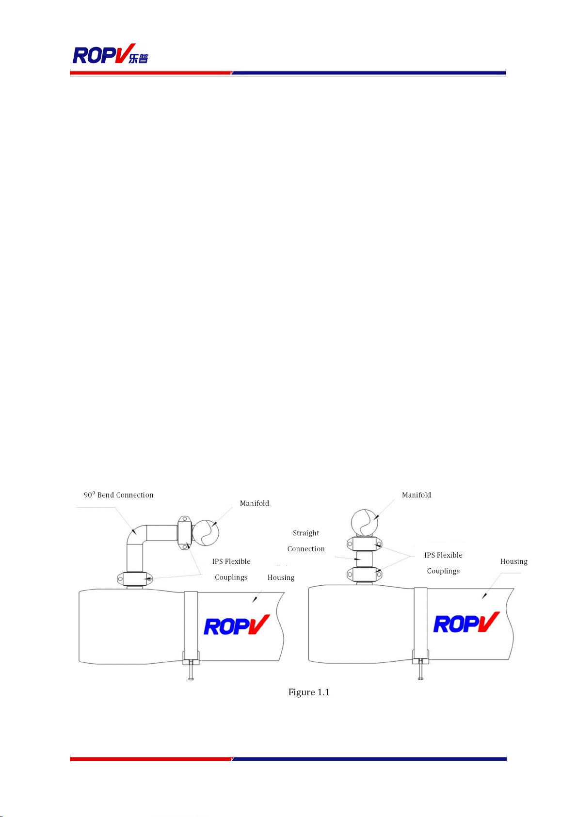
Align the side ports with the system manifold, correcting any misalignment before final
installation.
Provide overpressure protection in the system safety devices.
Inspect end closures regularly for signs of corrosion. Immediate corrective action
and/or replacement are suggested in case of corrosion.
Thrust Ring must be installed at the downstream end of the vessel.

7
Relieve system pressure before working on the vessel.
Do not attempt to over-tighten the Permeate Port connections as this may damage the
end closure. One turn past hand tight should be sufficient.
Never operate the vessel in excess of its ratings. This may void the warranty and cause
bodily or property damage.
Do not operate the vessel permeate port over 125PSI.
Flush the vessel with permeate before system shutdown to reduce the chance of
corrosion.
Do not install the vessel under direct sunlight.
Operate the vessel within the recommended pH range - Operating pH Range: 3 – 10,
Cleaning pH Range: 2 – 12 (less than 30 minutes).
Minimize membrane movement by careful shimming the membrane column.
Failure to understand and follow all precautions may void warranty and result in
catastrophic failure of the vessel.
These guidelines are subject to change. Please check with ROPV to ensure that the User
Manual is the latest version for the vessel model being used.

8
Chapter 2 Installation
2.1. Carefully study the vessel engineering drawings for key dimensions and
technical requirements.
2.2. Design and manufacture rack according to engineering drawings and system
capacity. Independent support of both pressure vessel and manifolds shall be
considered in the design of the rack.
2.3. Check the integrity of the vessel, especially the inner surface of the vessel and
the sealing surface of the Feed/Concentrate ports.
2.4. Ensure enough space is reserved around the two ends of the vessel for
installation and removal of the membrane elements.
2.5. Mount the vessel on the provided saddles at the recommended span positions
shown on the engineering drawings.
2.6. Connect the vessel to the manifolds and/or to the next vessel while adjusting
each vessel and manifold to minimize misalignment at each end. (For details, see
“Chapter 4 Piping Connections”).
2.7. Install the strap assembly. Install the screws through the hole in the rack and
thread them into the strap locknut; use a torque wrench to tighten the screws
within 3~5N.m.
NOTE: Pressure vessels expand during pressurization, over tightening the
strap assemblies will damage the vessel.
2.8. Assemble end closure(For details, see “Head Assembly” in “Maintenance Guide”)
2.9. Install membrane elements(For details, see “Membrane Elements Installation”
in “Maintenance Guide”)
2.10. Install thrust ring at the downstream end of the vessel.
2.11. Close the vessel.
2.12. Connect the permeate port manifolds (For details, see “Piping Connections”)
2.13. Inspect the installation. Inspection includes but is not limited to the position of
the vessel, the end caps and pipelines connections. Please inspect according to
“Pre-Pressurizing Checking list” in Appendix 1.
2.14. Pressurize and run the system.

9
Chapter 3 Piping Connections
Enough room shall be reserved for both axial and radial expansion of the vessel in the
design of the manifolds and pipelines; otherwise the vessel and other components of the
system could be damaged. Careful reading of this chapter will facilitate safe and normal
working conditions of the vessel and pipelines.
3.1. Permeate Port Connections
3.1.1. Use flexible connections to reduce vibration impact.
3.1.2. A U swan-neck tubing with flexible connectors at both ends, or one piece of
flexible soft pipe should be used for permeate port connections.
3.1.3. Extra and independent support shall be provided for permeate port pipelines
rather than using permeate port as support.
3.2. Feed/Concentrate Port Connections
3.2.1. Use flexible grooved couplings (IPS).
3.2.2. Do not connect any manifolds rigidly to the vessel.
3.2.3. Manifolds must be supported independently.
3.2.4. Manifold span should be greater than vessel span to allow for vessel growth
under pressure.
3.2.5. To reduce the risk of stress concentration we recommend that “two IPS
standard flexible couplings and one piping section” are used to connect the
Feed/Concentrate ports and manifold ports; this method lowers
requirements for housing alignment and the position accuracy of the
manifold welds. However, this method will increase the initial cost as shown
in figure 1.1.
3.2.6. The use of only one IPS standard coupling to connect directly to the
manifolds is also acceptable. However, the welding of the manifolds and the

10
Maximum Misalignment .76mm
Figure 1.3
installation position of the housing should be accurately controlled to ensure
the proper alignment of the manifold and the Feed/Concentrate ports.
3.2.7. Install the vessel correctly: Make sure to align the Feed/Concentrate ports
and the manifold ports at a right distance. Please contact the supplier of
coupling to get the exact distance.
3.2.8. Connecting the vessel and the manifold: Since only one IPS coupling is used to
connect directly to the manifold precautions shall be taken to ensure
additional flexible space is provided for the connection of vessels and
manifolds by adding an extra IPS coupling to the manifold, as shown in figure
1.2.
Slight angle between manifolds and F/C ports using IPS standard clamp for
connection is acceptable. However, high accuracy in alignment is required.
Misalignment in any direction should be avoided and keep to a minimum as
much possible since it will generate mechanical stress concentrations that
will damage the membrane housing.
3.2.10. Verify the alignment: There is a maximum of 0.76mm misalignment
tolerance in any direction for all ports as shown in figure 1.3. Severe
misalignment could impair the life expectancy of the vessel. Excessive force
to tighten the couplings is an indication of misalignment. When properly

11
aligned couplings should be able to turn slightly by hand after installation.
Chapter 4 Maintenance Guide
4.1. Preventive Maintenance
Periodical cleaning and maintenance of the vessel and replacement of damaged
components is essential to ensure a safe and normal operation of the vessel over a long
service life.
As a recommendation we suggest to follow the Prevention Checklist below:
End closures.
Periodically clean and remove any salt and/or corrosion deposits.
Inspect components for deterioration and replace as needed.
Maintain external components dry and leak free.
Side Ports.
Inspect for leakage.
Inspect coupling connections for corrosion and replace deteriorated
couplings as needed.
Maintain all side ports dry and leak free to prevent corrosion.
4.2. Opening the Vessel
4.2.1. Shut Down System and Relieve System Pressure – The system must be
shut down and all pressure relieved before conducting any maintenance or
repair on the vessel. Read and follow all related guides provided by system
provider.
4.2.2. Disconnect permeate port piping. Unscrew and remove the permeate port
piping using a wrench. Pay attention to the thread-turning direction to
Read this section completely before servicing the vessel.
DO NOT Service any component until you verify that
system pressure is fully relieved from the vessel and the
system is completely shut down.
WARNING

12
prevent any damage to the permeate port due to reversed turning or over-
turning.
4.2.3. Inspect End Closure – The end closure should be inspected for any signs
of corrosion or damage. Surface corrosion and salt deposits can be removed
with a brush or scrubbing pad, while flushing with water. Damaged
components should be replaced with approved components from ROPV.
4.2.4. Remove the locking kit segment screws using a hex wrench. Remove the
retaining ring. Remove the retaining ring.
4.2.5. Lift the locking kit segment out of the retaining groove using a screw
driver. Should the assemblies be difficult to remove, it may be necessary to
rock the head slightly or tap the head inward with a rubber mallet. Remove
the end closure. It is recommended to use dedicated end closure removal
tools from ROPV.
4.2.6. Remove the Head Assembly with One of the Following Techniques
4.2.6.1. ROPV Head Removal Tool– A head removal tool set is available from
ROPV. While not necessary for head removal, they have proven an
effective and easy way to remove the vessel head without causing any
damage to the vessel. There are four components: bearing block,
position nut, bearing rod, center piece.
Figure 2.3 ROPV Head Removal Tool
Figure 2.1
Figure 2.2

13
4.2.6.1.1. Thread the center piece into the permeate port of the head
assembly, to hand tight. Do not over tighten the center piece
(Fig. 2.4).
4.2.6.1.2. Place the bearing block at the end face
4.2.6.1.3. Thread the position nut into the center piece
4.2.6.1.4. Turn bearing rod clockwise. The head will move with the
bearing rod as it moves toward the end of the vessel. You will be
able to remove the head once it has cleared the retaining groove
area of the vessel.
4.2.6.2. Alternative Head Removal – It is possible to remove the head assembly
without the ROPV head removal tools. A 1” NPT Male threaded piece of
PVC (or similar material) pipe should be threaded into the head permeate
port to hand tightness. Pull the pipe outward to remove the head. If the
vessel has been in operation for an extended time, a slight rocking motion
or forceful tug may be required to break the head seal bond. Also, a handle
at the end of the pipe will ease head removal – forming a T with the pipe
that threads into the permeate port.
Figure 2.4
Figure 2.5
Figure 2.6
Figure 2.7

14
4.3. Head Disassembling.
Read this article carefully before disassembling the head assembly to
prevent damaging its components.
4.3.6. Inspection: Make sure that the end cap is removed from the vessel
according to <Opening the Vessel>
4.3.7. Remove the adaptor and seals: Hold the bearing plate tightly with one
hand and pull the adaptor out of the permeate port with the other hand;
remove the adaptor seals and the sealing plate seals.
4.3.8. Remove the permeate port locknut: Remove the locknut using a
dedicated wrench. The locknut is left hand threaded and must be turned
clockwise to be removed.
4.3.9. Separate the bearing plate and sealing plate. Pull the sealing plate with
one hand to separate it from the bearing plate.
4.3.10. For parted seal plates, pull the permeate port out of the sealing plate
and remove the permeate port seals and the seals inside the sealing plate.
Figure 2.10
Figure 2.8 Remove
the locknut
Figure 2.9 Remove
sealing plate

15
4.3.11. Remove the permeate port seals.
Carefully remove the seals to prevent damage to the
sealing surfaces. It is recommended to replace all used
seals with brand new seals.
NOTE
4.4. Head Assembly Cleaning and Inspection.
Please read this section carefully before making decisions and taking
measures on component structure or corrosion problems. Please combine the
operational experience with this manual to deal with corrosion and
component damage. You can refer to <Breakdowns and solutions> for the
content that is not included in this section or contact ROPV for conditions not
covered in this manual.
4.4.1. Cleaning and Inspection of the metallic components.
Metallic components include the aluminum bearing plate, stainless steel
locking kit segments and screws.
4.4.2. Inspect the components for scale, salt deposit or corrosion; use a steel
brush or a scrubbing pad to loosen any deposit. Be careful not to scratch the
bearing plate anodize coating.
4.4.3. Place the components into a vessel filled with mild soap solution and
remove the corrosion.
Figure 2.11 Head breakdown figure 1(sealing plate)
Components:sealing plate, adaptor,bearing plate,permeate
port plug,permeate port locknut,seals.

16
4.4.4. Flush all components with clean water.
4.4.5. Dry the components with compressed air or a clean and dry towel.
4.4.6. Inspect all components carefully, check for any structural defects or
damage in the bearing plate anodized coating. Replace any damaged or
defective component.
4.5. Cleaning and Inspection of the non-metallic components. Non-metallic
components include sealing plate, permeate port, adaptor, permeate port
locknut, permeate port plug and all seals.
4.5.1. Inspect components for scale, corrosion or salt deposit. Place the
components into a bucket filled with mild soap solution and clean them to
remove the deposits.
4.5.2. Flush all components with clean water.
4.5.3. Dry the components with compressed air or a clean and dry towel.
4.5.4. Inspect all components carefully for any structural defects or damage in
the seals. For example, cracks in the permeate port or the locknut, damage
in the threads; aged, deformed or damaged seals. Replace any damaged or
defective component with new ones
4.5.5. Replace all components that need to be changed upon inspection
4.5.6. Inspect carefully the Feed/Concentrate ports and attachments to the shell
to ensure that connections and seals are structurally sound. Please contact
ROPV for any questions.
Please do not conduct any repair work before consulting with the manufacturer
for guidance, except for replacing head components.
4.6. Head Assembly
Read and follow this section. Incorrect assembly may result in catastrophic head
failure.
4.6.1. Lubricate and install the seals
If chemical reaction problems occur like cracks or
discoloration on the vessel or its components, please
NOTE
We recommend using brand new seals for head
assembly.
Lubricate seals using glycerin or silicone base
lubricant.
ATTENTION

17
4.6.1.1. Lubricate the permeate port seals and place them in the grooves.
4.6.1.2. Lubricate the sealing plate seal and place it in the groove located
on the inside diameter of the sealing plate. Lubricate the permeate port
seals and place them in the grooves located on the inside diameter of
the permeate port. Lubricate the permeate port seals and place it onto
the outer edge of the permeate port.
Figure 2.13 Install the permeate port seals
Figure 2.14 O-ring installation for parted seal plate
Figure 2.15 Adaptor seals
installation

18
4.6.1.3. Lubricate the adaptor seals and place them in the grooves of the
adaptor.
4.6.2. Assemble the sealing plate and bearing plate.
4.6.2.1. Apply a thin layer of lubricant onto the surface of the permeate
port and push the permeate port through the hole of the parted sealing
plate.
4.6.2.2. Insert the threaded end of the permeate port through the hole of
the bearing plate until full contact of the sealing plate and bearing plate.
4.6.2.3. Thread the permeate port locknut onto the threads of the
permeate port using a wrench until the sealing plate and bearing plate
are thoroughly contacted.
4.6.2.4. Install the adaptor. Insert the end without seals into the hole of
the permeate port.
4.6.2.5. Install the head O-ring. Lubricate the O-ring and seat it into the
groove located on the outside diameter of the sealing plate.
Figure 2.16 Assembling parted seal plate
Figure2.17 Assembling bearing plate
Figure 2.18 Locknut installation
Figure 2.19 Adaptor installation

19
Figure 2.20 Head assembly
This manual suits for next models
2
Table of contents